Albatros DII R/C Scale Model Instructions - AerodromeRC
Albatros DII R/C Scale Model Instructions - AerodromeRC
Albatros DII R/C Scale Model Instructions - AerodromeRC

You also want an ePaper? Increase the reach of your titles
YUMPU automatically turns print PDFs into web optimized ePapers that Google loves.
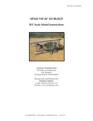
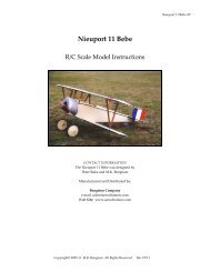
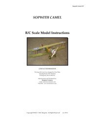
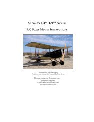
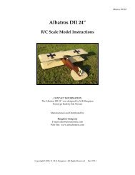
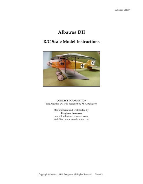
<strong>Albatros</strong> <strong>DII</strong><br />
R/C <strong>Scale</strong> <strong>Model</strong> <strong>Instructions</strong><br />
CONTACT INFORMATION<br />
The <strong>Albatros</strong> <strong>DII</strong> was designed by M.K. Bengtson<br />
Manufactured and Distributed by:<br />
Bengtson Company<br />
e‐mail: sales@aerodromerc.com<br />
Web Site: www.aerodromerc.com<br />
Copyright© 2005‐11 M.K. Bengtson All Rights Reserved Rev 07/11<br />
<strong>Albatros</strong> <strong>DII</strong> 36”
<strong>Albatros</strong> <strong>DII</strong><br />
Thank you for purchasing the <strong>Albatros</strong> <strong>DII</strong> model for<br />
electric flight.<br />
THE MODEL<br />
A semi scale adaptation of the <strong>Albatros</strong> <strong>DII</strong>, this model is<br />
designed to be easy to build and exciting to fly.<br />
Finished <strong>Model</strong> by Dave Ottney<br />
POWER SET UP<br />
The 6V S400 motor powers the model using the Mini‐<br />
Olympus 2.33:1 Gearbox and a 10x4.7 APC prop. Battery<br />
power pack is an 8 cell 600maH Nicad or an equivalent<br />
weight Nimh<br />
SPECIFICATIONS<br />
More than 215 laser cut parts<br />
<strong>Scale</strong>: ~1/10<br />
Wingspan: 36ʺ<br />
Wing Area: 442 sq in<br />
Weight: 24 oz<br />
Channels: R/E/A/T<br />
Power System: Speed 400, Mini‐Olympus 2.33:1 gearbox<br />
Prop: 10x6<br />
Wheels: Balsa & plywood, Neoprene foam tires<br />
Airfoil Type: Flat bottomed<br />
Spinner: Foam and fiberglass<br />
Decals: Available on website<br />
Covering: Litespan or Polyspan<br />
BUILDING THE MODEL<br />
BEFORE STARTING<br />
A note about the photos: The photos were taken of a<br />
prototype and the parts supplied may look slightly<br />
different from them. However, the concepts illustrated<br />
are the same.<br />
WINGS<br />
Copyright© 2005‐11 M.K. Bengtson All Rights Reserved Rev 07/11<br />
<strong>Albatros</strong> <strong>DII</strong> 36” Page 1<br />
Wing Construction<br />
Pin down, over the plan, the t/e, spars and wing tip,<br />
gluing as required. Add the leading edge stock after the<br />
basic frame is done as the stock is inserted in a rotated<br />
fashion. Add the wing tips and align the front tip along<br />
the center of the leading edge. Sand the leading edge<br />
stock to be rounded and meet the ribs.<br />
Wing Pinned to Plan<br />
Scalloping can be done easily by fitting sandpaper on a<br />
dowel or other appropriately shaped object and simply<br />
sand the scallops. Start sanding at the center point of the<br />
scallop and stop as soon as the desired depth is reached.<br />
Wing Detail (Note: Photo is of the <strong>Albatros</strong> <strong>DII</strong>I Aileron)<br />
The leading edge of the aileron is rounded over with<br />
sandpaper to make the aileron movable with a minimum<br />
gap. The trailing edge of the wing in that section is left<br />
flat.<br />
FUSELAGE CONSTRUCTION<br />
The fuselage is built as two side structures, which are then<br />
joined over the plan. This system not only keeps each<br />
stage simple, but it also helps to ensure a straight fuselage.
Building the Fuselage<br />
Begin by building two fuselage side frames over the plan<br />
and allow to dry.<br />
Frame Construction Detail<br />
Join the two frames over the plan with cross braces and<br />
the tail skid mount F7. Check, check and check again that<br />
this and ALL other structures remain perfectly aligned.<br />
The right side of the fuselage is a bit shorter than the left<br />
side. This is to build in right thrust and allow the spinner<br />
to rotate properly on the model. Former F1 is also angled<br />
a bit for down thrust. Place F7 carefully. It is designed to<br />
run down the centerline of the fuselage. It serves to<br />
position the vertical stabilizer and tail skid. Use a length<br />
of 1/4” diameter birch or hard balsa dowel at the end of<br />
the fuselage. This gives the fuselage a nice rounded<br />
termination.<br />
Fuselage Construction Detail<br />
Fuselage Bottom Stringers<br />
Copyright© 2005‐11 M.K. Bengtson All Rights Reserved Rev 07/11<br />
<strong>Albatros</strong> <strong>DII</strong> 36” Page 2<br />
Fuselage Nose Filler Balsa Blocks<br />
Sand Fuse to Shape<br />
Adding the Decking<br />
Add all the stringers and formers, and carefully trim to<br />
size and fit 1/32” sheeting (sheeting is optional). Some<br />
have also sheeted the fuselage sides with 1/32” balsa as<br />
well. Keep in mind that excess weight in the tail is to be<br />
avoided, so use these sheeting options with the lightest<br />
balsa available.<br />
Decking Construction Detail<br />
Optional 1/32” balsa sheeting is shown over stringers.
Blue Foam Inserted to Shape Fuselage<br />
Blue Foam Sanded to Shape<br />
Sand the blue foam to shape.<br />
Dave chose to sheet the entire top, bottom and sides of the<br />
model with 1/32” balsa.<br />
Sheeted Top, Bottom and Sides<br />
It weighs only 3 oz.<br />
Adding The Undercarriage Plates<br />
Copyright© 2005‐11 M.K. Bengtson All Rights Reserved Rev 07/11<br />
<strong>Albatros</strong> <strong>DII</strong> 36” Page 3<br />
Remove from the board and add the plywood crosspieces<br />
that serve as u/c plates.<br />
TAIL SURFACES<br />
Lay out and glue parts of the tail surfaces on the plans.<br />
Tail Surface Detail<br />
Sand the tail parts, rounding off all edges. Don’t add the<br />
horns or hinge the surfaces until after covering is<br />
complete.<br />
Tail Surfaces Pinned on Plans<br />
LANDING GEAR<br />
The undercarriage is made from two pairs of 1/16” wire<br />
cut to the shapes as shown on the plan. Each half inserts
into the mounting blocks, which are attached to the<br />
fuselage. They are set in place using epoxy. The joints<br />
where the axle and U/C legs meet should be cleaned with<br />
the wire bush on a Dremel tool. With the joints nice and<br />
shiny, a bit of brass or copper wire binds the joints. Solder<br />
using plenty of heat.<br />
Some modellers prefer an alternate method. Instead of<br />
wire and solder, lash the parts together with Kevlar<br />
thread and CA glue. Finish the joint with epoxy. This<br />
method always works and avoids the cold solder joint that<br />
can fail in time. Be sure to use Kevlar or Nylon thread, as<br />
common cotton thread will fail.<br />
It is best to attach the landing gear after the bottom of the<br />
fuselage is covered and painted as covering and painting<br />
with the gear on is awkward.<br />
DUMMY MOTOR<br />
Dummy Motor Mounted In Place<br />
Assemble the dummy motor from the balsa parts supplied<br />
and sand to shape. Not all the parts of the engine are<br />
supplied as some are best fabricated from other materials.<br />
Solid 16 gauge copper electrical wire (black insulated )<br />
makes an excellent “radiator hose”.<br />
Copyright© 2005‐11 M.K. Bengtson All Rights Reserved Rev 07/11<br />
<strong>Albatros</strong> <strong>DII</strong> 36” Page 4<br />
Spinner Components<br />
The spinner is composed of fiberglassed blue foam. The<br />
spinner is made from blue foam which is tack glued to a<br />
piece of 1/32” ply. Epoxy a short 1/4” diameter dowel to<br />
the back in the center of the disk. Place the assembly in a<br />
drill chuck and sand the foam to shape while it spins.<br />
Glass the foam using standard glassing techniques. (Note,<br />
Minwax Polycrylic is an excellent substitute for epoxy).<br />
When the epoxy is ready, cut the excess fiberglass away.<br />
Then remove the plywood and carve out the necessary<br />
recess for the propeller. Drill out the dowel on the<br />
plywood disk. Glue the spinner to the plywood disk after<br />
the prop is mounted to the model. It should be perfectly<br />
aligned with the fuselage. It looks complicated but in<br />
practice the process goes easily and works very well.<br />
Spinner Detail<br />
COVERING<br />
Any lightweight covering material can be used. Polyspan<br />
makes a good choice although Litespan is also popular.<br />
Dave Ottney used Litespan. He also used stain and a<br />
streaked wood finish for the fuselage.Downloadable decal<br />
outlines are available on‐line at<br />
http://www.aerodromerc.com/decals.<br />
Assembled <strong>Model</strong> Ready to Cover
WHEELS<br />
Gluing the ply sides on the ¼ “balsa core makes the basis<br />
for the wheels. Use the brass hub for alignment. Epoxy<br />
the hubs in place and add a sufficient amount of epoxy<br />
around the base of the hub to reinforce the connection of<br />
the hub to the ply. Plywood reinforcing hubs are<br />
provided that are to slip over the brass tubing as shown.<br />
Alternatively, gluing an additional ½” square piece of<br />
scrap 1/8” balsa with a hole drilled in the center can be<br />
substituted. Next, CA glue the neoprene cording together<br />
to from a “tire”. Use thin CA sparingly as the CA bonds<br />
very aggressively to the rubber. Press the CA wetted ends<br />
together for an instant bond. The best way to align the<br />
ends is to glue them while they are in place on the wheel.<br />
Then attach the tires to the wheels and CA in place. A<br />
thin bead of CA around the rim makes for a secure tire.<br />
Paper cones are cut out. Use a ballpoint pen to score each<br />
line on the back to make an impression of “spokes.” It is<br />
helpful to do this operation on a paper tablet so that the<br />
pen makes a good crease. Fold the paper along the crease<br />
lines to exaggerate the raised lines. One of the sections<br />
forming a wedge is cut out. Make cuts to the center of the<br />
circle along a pair of the spokes. Close the paper cut‐out<br />
to form a cone and tape the joint inside the cone.<br />
Completed Wheels<br />
The inside cones may now be attached to the wheels. The<br />
outside cones may be attached at this point if wheel<br />
collars are to be used. Alternatively, after installing the<br />
wheels on the landing gear, a washer may be soldered to<br />
Copyright© 2005‐11 M.K. Bengtson All Rights Reserved Rev 07/11<br />
<strong>Albatros</strong> <strong>DII</strong> 36” Page 5<br />
hold the wheel in place and then the cone is attached.<br />
This method makes a very nice scale appearance.<br />
INSTALLING THE RADIO CONTROL GEAR<br />
Aileron Servos<br />
Aileron servos are mounted in wing and attached with<br />
short threaded rods to the ailerons. Use a “Y” wiring<br />
harness connector to wire the servos to a single radio<br />
connection. If differential aileron throws are desired,<br />
rotate each servo horn forward about 20 degrees, while<br />
maintaining the neutral position of the aileron. This<br />
should counter any adverse aileron yaw.<br />
Battery Tray<br />
After all the above has been placed, mount the battery<br />
tray made from 1/8” balsa and use the battery position to<br />
balance the model as shown on the plan.<br />
ASSEMBLY<br />
Wing<br />
Using Locating Dowels And Aligning Wing Panels<br />
The first task is to epoxy the lower wings accurately onto<br />
the fuselage. Use 5‐minute epoxy for this task. Apply<br />
epoxy to the wing rib that meets the fuselage. Attach the<br />
wings to the fuselage. Use the locating dowels to assist<br />
with aligning the wing panels. Allow epoxy to set.<br />
After the lower wings are attached, the struts are inserted.<br />
Use music wire lashed and CA glued to the laser cut ply<br />
cabane struts as strengtheners and attachment points to be<br />
epoxied into hard bass blocks in the top wings. The top<br />
wing is added and epoxied in place.<br />
Fitting Tail Surfaces<br />
The horizontal stabilizer is in two halves and has tabs that<br />
fit into slots in the side of the fuselage. Insert the two<br />
halves, and dry fit the elevator using CA hinges. The<br />
elevator serves as an alignment tool so that the horizontal<br />
stab can be CA glued in place. The vertical stabilizer also<br />
fits into a slot in the top of the fuselage formed in F7.<br />
Control Horns On The Pushrod Ends<br />
Slip the control horns onto the wire pushrod ends and,<br />
with both the servos and the control surfaces centered,<br />
glue the horns into their slots.<br />
Fitting the rigging wires.<br />
Use strong thread or Kevlar fishing line or elastic beading<br />
cording to simulate rigging wires. Use small screws,
fishing hook eyes, straight pinheads or small eyelets to<br />
attach the lines. While not technically required these<br />
wires can add a degree of strength to your model.<br />
Windsock Datafiles “<strong>Albatros</strong> Fighters “publication has<br />
details on placement and markings. Available at<br />
http://www.aeroplanebooks.com/<br />
Battery hatch<br />
Fashion a Battery Hatch from Soft Balsa<br />
Battery Hatch Detail<br />
Servo Bay Detail<br />
Balancing The <strong>Model</strong><br />
Copyright© 2005‐11 M.K. Bengtson All Rights Reserved Rev 07/11<br />
<strong>Albatros</strong> <strong>DII</strong> 36” Page 6<br />
Balance the model at the point shown. It is best to<br />
position the battery to do this operation.<br />
FLYING<br />
The model should ROG on pavement or hard surfaces.<br />
On grass, the model may require hand launching. Be<br />
careful that your hand or fingers do not catch on the lower<br />
rigging. Launch firmly and level.<br />
Let the model gain altitude slowly off the runway.<br />
Applying too much up elevator at slow speeds risks a<br />
stall. Make your turns gently as tight turns risk tip<br />
stalling in any model. Don’t expect the elevator to make<br />
the model climb. Think of the elevator as a device to<br />
change the attitude of the model. The wing and airspeed<br />
ultimately make the model climb. Often down elevator<br />
applied at stalling can avoid a major crash. The most<br />
important details for proper flight operations are:<br />
1. CG location. Tail‐heavy models never fly well or<br />
at all.<br />
2. Down and right thrust<br />
3. Straight and non‐warped wings.<br />
Finished <strong>Model</strong><br />
CONTACT INFORMATION<br />
Distributed by:<br />
Bengtson Company<br />
e‐mail: sales@aerodromerc.com<br />
Web Site: www.aerodromerc.com