Nieuport 11 Bebe - AerodromeRC
Nieuport 11 Bebe - AerodromeRC
Nieuport 11 Bebe - AerodromeRC

Create successful ePaper yourself
Turn your PDF publications into a flip-book with our unique Google optimized e-Paper software.
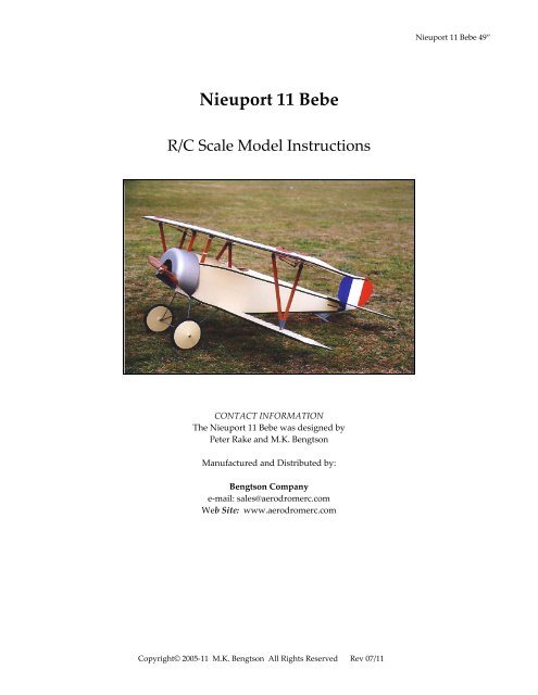
<strong>Nieuport</strong> <strong>11</strong> <strong>Bebe</strong> 49”<br />
<strong>Nieuport</strong> <strong>11</strong> <strong>Bebe</strong><br />
R/C Scale Model Instructions<br />
CONTACT INFORMATION<br />
The <strong>Nieuport</strong> <strong>11</strong> <strong>Bebe</strong> was designed by<br />
Peter Rake and M.K. Bengtson<br />
Manufactured and Distributed by:<br />
Bengtson Company<br />
e‐mail: sales@aerodromerc.com<br />
Web Site: www.aerodromerc.com<br />
Copyright© 2005‐<strong>11</strong> M.K. Bengtson All Rights Reserved Rev 07/<strong>11</strong>
<strong>Nieuport</strong> <strong>11</strong> <strong>Bebe</strong> 49” Page 2<br />
<strong>Nieuport</strong> <strong>11</strong> <strong>Bebe</strong> 49”<br />
Thank you for purchasing the <strong>Nieuport</strong> <strong>11</strong> <strong>Bebe</strong> model<br />
plans for electric flight.<br />
Very few modellers can be unfamiliar with the <strong>Nieuport</strong><br />
range of vee strutted fighter aircraft of WW1, and the<br />
<strong>Nieuport</strong> <strong>11</strong> is the one that got them all started. Although<br />
originally designed as a pre war racing plane, she was<br />
developed into one of the several types that brought about<br />
the end of the ‘Fokker Scourge’, a very dark era for allied<br />
airmen. Built both in France, and under licence in Italy,<br />
and used by most of the allied nations armed forces, there<br />
are many colour schemes available to us as modellers, and<br />
many minor variations in detail to enable each model to<br />
be slightly different. You could even build her as the more<br />
powerful N16, as used by the Belgian forces, although,<br />
because of the bigger engine, they did have the habit of<br />
diving headlong if the engine cut.<br />
THE MODEL<br />
As with other models in this range, the N<strong>11</strong> is not<br />
intended as an exact scale model. It has been simplified<br />
slightly, so that while it still coveys the ‘feel’ of the full<br />
size aircraft, it remains easy to build and pleasant to fly.<br />
Designed to use a relatively inexpensive power set up,<br />
with mini servos to keep the weight down, she is an ideal<br />
entry into slightly larger electric powered scale models,<br />
without involving huge expense for the builder.<br />
SPECIFICATIONS<br />
More than 150 laser cut parts<br />
Scale: 1/6<br />
Channels: R/E/A/T<br />
Wingspan: 49ʺ<br />
Wing Area: 570 sq in<br />
Weight: 61 oz<br />
Power System: Speed 600BB Olympus belt drive; 2.3:1<br />
Prop: 12x8<br />
Wheels: Balsa & plywood, Neoprene foam tires<br />
Airfoil Type: Flat bottomed<br />
Cowl: Built up balsa and plywood<br />
Spinner: N/A<br />
Designer: Peter Rake/M.K. Bengtson<br />
WINGS<br />
To ease the builder into this model, the bottom wings are<br />
where we start construction. They are quite easy to build,<br />
and won’t take up too much space once completed. Make<br />
up the entire strut and wing plates from the aluminium<br />
strip supplied so that they are readily to hand when you<br />
need them. Roughen all gluing areas with coarse sand<br />
paper to provide a key.<br />
BOTTOM WING<br />
Begin the actual construction by pinning down, over the<br />
plan, the lower trailing edge strip, the wingtip, the spar<br />
and the leading edge, gluing as required. Make up the rib<br />
doubler by notching it to accept the strut plate and<br />
EPOXY the strut rib, strut plate and doubler together as<br />
indicated on the plan. Now, using the rib angle gauge to<br />
set up the root rib, glue all the wing ribs in place. With the<br />
exception of the root rib, all ribs should be vertical to the<br />
building board. Glue in place the 1/8” balsa tip gusset,<br />
and the 1/8” ply mounting plates and allow to dry<br />
thoroughly before proceeding.<br />
Remove the wing from the board and trim the rear of the<br />
lower trailing edge to follow the line of the ribs, before<br />
pinning the wing back over the plan. Add the upper<br />
trailing edge strip and the 1/16”x3/16” cap strips, and<br />
once again allow to dry. Repeat the process for the<br />
opposite wing panel, and then trim and sand the wings to<br />
shape. Note that the wing tip is trimmed down to mate<br />
accurately with the trailing edge. The locating dowels<br />
may be added now, or left until after the wing panels are<br />
covered.<br />
TOP WING<br />
Please note that the aileron is built integral with the top<br />
wing, only being separated after the panels have been<br />
trimmed and sanded to shape.<br />
As with the bottom wings, pin down the leading edge,<br />
lower trailing edge strip, bottom spars and wing tip<br />
pieces, gluing as required. Also pin down and glue the<br />
centre section cut out laminations. Laminate up, and trim<br />
to shape the balsa and ply wing joiner brace and glue it<br />
securely against the lower main spar. Glue all the main<br />
ribs in place; ensuring that they are upright, but DO NOT<br />
add the aileron ribs at this stage. Glue the top spars in<br />
position, followed by the vertical grain spar web pieces<br />
and the 1/8” balsa false trailing edge. Add the tip gusset,<br />
hatch blocks, ply mounting plates, doubler and wing bolt<br />
support block, and then SPOT GLUE the aileron leading<br />
edge to the false trailing edge, while gluing it securely to<br />
the aileron tip. Now, glue in place the aileron ribs and<br />
horn support piece, and allow to dry completely.<br />
Copyright© 2005‐<strong>11</strong> M.K. Bengtson All Rights Reserved Rev 07/<strong>11</strong>
<strong>Nieuport</strong> <strong>11</strong> <strong>Bebe</strong> 49” Page 3<br />
Remove the wing from the board, and trim the trailing<br />
edge strip, the false trailing edge, the aileron leading<br />
edge, wing cut out block and the wing bolt block to follow<br />
the line of ribs, before pinning back down again and<br />
adding the upper trailing edge and cap strips. Allow to<br />
dry thoroughly before trimming and sanding to shape.<br />
DO NOT add the strut plates yet!!!!<br />
Position the built wing panel accurately against the<br />
drawing for the opposite wing panel, pin it securely in<br />
place, and build the other wing onto it, following the<br />
same procedure as before. Once this wing has also been<br />
trimmed and sanded, the strut plates and doublers should<br />
be firmly glued to the liteply strut ribs. Just remember<br />
that these ones go under the wing. Make up the servo<br />
hatches, provide somewhere for the servo leads to run<br />
through the wing and carefully and accurately drill the<br />
holes for the self tapping screws and nylon bolt that will<br />
retain the top wing. Now you can cut the ailerons from<br />
the rest of the wing, shape the leading edge as shown, and<br />
prepare them for hinging. Your wings are now ready to<br />
cover, have the ailerons hinged and the control horns<br />
fitted. Fit the servos, and with the ailerons held level with<br />
the wings, make up the pushrods. Use a z bend in the<br />
threaded rod at the servo output arm, and a clevis at the<br />
control horn end.<br />
SERVO LEADS<br />
I have found it helpful to use socket‐to‐socket extension Y<br />
leads in the wings of this type of model, and a plug‐toplug<br />
extension lead from the receiver. By mounting the Y<br />
lead socket, into which the extension lead will plug, just<br />
proud of the lower centre section (top wing), it is possible<br />
to run the extension lead up one of the struts, disguised as<br />
a fuel line or similar, and avoid the need for a hatch in the<br />
centre section. No doubt you’ll use whatever system<br />
you’re used to, but this one is worth a try. Even if there<br />
shouldn’t actually be a fuel line, it will still look better<br />
than a servo lead. The servos should be fixed to the<br />
hatches with servo tape, or screwed to hardwood blocks<br />
glued to the hatches. The output arm should extend<br />
through the hatch and there should be no binding in<br />
operation.<br />
TAIL SURFACES<br />
These are simply built over the plan, from the pre cut<br />
parts and strip balsa. Sand overall and round off all the<br />
edges. Bend up the wire elevator joiner, and carefully drill<br />
the holes into which the joiner will fit. Cut a groove in<br />
each elevator, to enable the joiner to sit flush, and epoxy<br />
the elevators onto the joiner. Make sure that they match<br />
the width of the tailplane, and that they are both level<br />
with each other. Glue the ply horns in place after<br />
covering.<br />
FUSELAGE<br />
The fuselage of this model is built as two separate<br />
sections, a front and a rear, which are then joined, since<br />
this is the surest way of easily producing a straight<br />
structure. An absolutely vital ingredient of this type of<br />
model.<br />
Begin assembly by building the two rear frames over the<br />
plan. Having built one side frame, allow it to dry before<br />
removing from the board, turning it over and building the<br />
second frame on top of the first. Use some clear polythene<br />
sheet between the two frames to prevent them sticking to<br />
each other, and ensure that both frames are identical.<br />
Now, once again working over the plan, join the two<br />
frames using the cross braces, and the piece of 3/16” balsa<br />
that the tail skid fits into. Make every effort to ensure that<br />
the structure is not only straight, but also totally square.<br />
Allow this assembly to dry completely before adding the<br />
1/16” balsa fill to the underside, and the two 1/16”<br />
pushrod exit pieces. Even if you intend to use closed loop<br />
type control links, still fit the exit parts since they add a<br />
lot of strength for very little weight. Set this assembly to<br />
one side, and move on to the front section of the fuselage.<br />
Start by joining the 3/16” balsa parts that make up the two<br />
basic side sheets and allow them to dry. Making sure that<br />
the structure remains perfectly straight and square, join<br />
the side sheet parts using formers F1A, F1B, F2 and the<br />
3/16” ply motor plate. Take especial care to get the motor<br />
plate the right way up. Left side thrust built into your<br />
model will not help its flying qualities in the least. Allow<br />
the glue to dry, and then add the parts F3 and F4,<br />
complete with the triangular reinforcing blocks. Bend up<br />
and drill the dural c/s struts, drill the strut plates, and bolt<br />
the struts securely in place. Lock off all the nuts with a<br />
spot of CA to ensure they don’t come loose again at a later<br />
date. Now, working over the plan to aid accurate<br />
alignment, join the front and rear fuselage halves.<br />
So, now that you have something resembling a fuselage,<br />
add the 3/32” lower fill pieces, formers D1 ‐ D7 and the<br />
1/8”x1/4” rear piece. Follow this by the 1/16” sheet<br />
decking and the stringers. The stringers butt against D3<br />
and the 1/8”x1/4” piece, the latter being shaped to follow<br />
the lines of the stringers. Sand the structure overall, before<br />
Copyright© 2005‐<strong>11</strong> M.K. Bengtson All Rights Reserved Rev 07/<strong>11</strong>
<strong>Nieuport</strong> <strong>11</strong> <strong>Bebe</strong> 49” Page 4<br />
drilling the holes for the u/c bindings and the lower wing<br />
retaining screws. It will result in a neater job if the bottom<br />
of the fuselage is covered before the u/c legs are bound in<br />
place and bound and soldered to the axle. Although no<br />
u/c fairings are shown, scrap balsa may be used to fair the<br />
legs.<br />
COWL<br />
Start by laminating up the C1 parts, and while this dries<br />
glue the 1/32” ply around C2 and C3. Make sure that C2<br />
and C3 align correctly or you’ll end up with a very<br />
lopsided cowl. Glue the laminated section onto the main<br />
cowl and then trim and sand to shape. Now, tack glue the<br />
cowl accurately to the fuselage, and glue the fairing<br />
blocks to the cowl. Note that they are ONLY glued to the<br />
COWL, not to the fuselage. Remove the cowl and trim<br />
and sand the cowl fairings to shape. Thoroughly prime<br />
and seal the cowl ready for painting. The cowl may either<br />
be glued or screwed to the finished model.<br />
FINISHING<br />
Although we all have our own preferred covering<br />
method, do ensure that you don’t add too much weight at<br />
this stage. The new matt covering from Solarfilm would<br />
be a good compromise between weight and durability,<br />
but ‘Tex’ coverings are on the heavy side. Modelling<br />
enamels are a good finishing medium, but try to limit<br />
their use to avoid adding weight.<br />
Since Williams Brothers supply excellent 1/6 scale model<br />
guns and pilot figures, even wheels if you don’t mind the<br />
weight, obtaining a good level of scale detail is easy.<br />
However, always bear in mind that a little detail can soon<br />
add a lot of weight. Weight is the key to success with<br />
electric powered models ‐ the less weight, the more likely<br />
you are to succeed.<br />
WHEEL ASSEMBLY<br />
Balsa Core<br />
Laminate the 1/8” thick balsa core to the ¼” thick balsa<br />
core using CA.<br />
BALSA PLY SANDWICH<br />
Gluing the ply sides on the 3/8“ balsa core makes the basis<br />
for the wheels. Use the brass hub for alignment. Epoxy the<br />
hubs in place and add the 1/8” plywood reinforcing collar<br />
to both sides. Allow to cure.<br />
TIRES<br />
Next, CA glue the neoprene cording together to from a<br />
“tire”. Use thin CA sparingly as the CA bonds very<br />
aggressively to the rubber. Press the CA wetted ends<br />
together for an instant bond.<br />
ATTACH TIRES<br />
Then attach the tires to the wheels and CA in place. A thin<br />
bead of CA around the rim makes for a secure tire.<br />
MAKE PAPER CARD CONES<br />
Paper cones are cut out and a wedge is cut out by making<br />
cuts to the centre along one wedge of the spokes. Use a<br />
ball point pen to score each line on the back to make an<br />
impression of “spokes” It is helpful to do this operation<br />
on a paper tablet so that the pen makes a good crease.<br />
Fold the paper along the crease lines to exaggerate the<br />
raised lines. Close the paper cut outs to form cones and<br />
tape the joint inside the cone.<br />
FIT CONES TO WHEELS<br />
The inside cones may now be attached to the wheels. The<br />
outside cones may be attached at this point if wheel<br />
collars are to be used. Alternatively, after installing the<br />
wheels on the landing gear, a washer may be soldered to<br />
hold the wheel in place and then the cone is attached. This<br />
method makes a very nice scale appearance.<br />
ASSEMBLY<br />
With the top wing inverted, carefully, and accurately,<br />
position the fuselage over it. Mark the positions of the<br />
wing mounting screws and bolt, and drill the appropriate<br />
holes. Carefully measure the lower wing screw positions,<br />
drill them and fit the wings to the fuselage. Make up the<br />
interplane struts over the full size drawing, and bolt them<br />
to the relevant strut plates. This will pull the dihedral into<br />
the bottom wing, but make sure that you haven’t also<br />
pulled any twist into the wings. Now use this assembly as<br />
a guide to alignment while gluing the tailplane firmly in<br />
place. Ensure that the all moving rudder is accurately<br />
aligned, but also that the hinges are both glued and<br />
pinned for security. The last thing you need is too lose<br />
your rudder mid flight. Make up the radio hatch, using<br />
your favourite retaining method, complete the radio<br />
installation and stand back and admire your handiwork.<br />
You are now the proud owner of a miniature <strong>Nieuport</strong> <strong>11</strong><br />
‘<strong>Bebe</strong>’.<br />
Copyright© 2005‐<strong>11</strong> M.K. Bengtson All Rights Reserved Rev 07/<strong>11</strong>
<strong>Nieuport</strong> <strong>11</strong> <strong>Bebe</strong> 49” Page 5<br />
FLYING<br />
In common with all model aircraft, and short nosed<br />
biplanes in particular, ensure that she balances just<br />
SLIGHTLY nose down when supported at the point<br />
shown. There is no surer way of destroying your model<br />
than to attempt to fly her in a tail‐heavy state.<br />
Open the throttle gradually, holding in some up elevator<br />
until she is moving, and allow her to pick up speed. Ease<br />
off the elevator as her speed increases, and be ready to<br />
correct any swing with rudder. Once she has attained<br />
speed, gradually feed in some more up elevator until she<br />
lifts off. Allow her to climb away steadily, and don’t<br />
attempt to rush things. Once you have made some height<br />
and trimmed her out, she’s all yours to have fun with.<br />
Loops, stall turns and even a not very crisp roll are all<br />
within her capabilities, so just enjoy her. However, at all<br />
times ‐ BEWARE THE HUN IN THE SUN.<br />
CONTACT INFORMATION<br />
Distributed by:<br />
Bengtson Company<br />
e‐mail: sales@aerodromerc.com<br />
Web Site: www.aerdromerc.com<br />
Copyright© 2005‐<strong>11</strong> M.K. Bengtson All Rights Reserved Rev 07/<strong>11</strong>