SOPWITH CAMEL R/C Scale Model Instructions - AerodromeRC
SOPWITH CAMEL R/C Scale Model Instructions - AerodromeRC
SOPWITH CAMEL R/C Scale Model Instructions - AerodromeRC

You also want an ePaper? Increase the reach of your titles
YUMPU automatically turns print PDFs into web optimized ePapers that Google loves.
Sopwith Camel 50”<br />
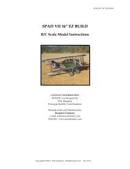
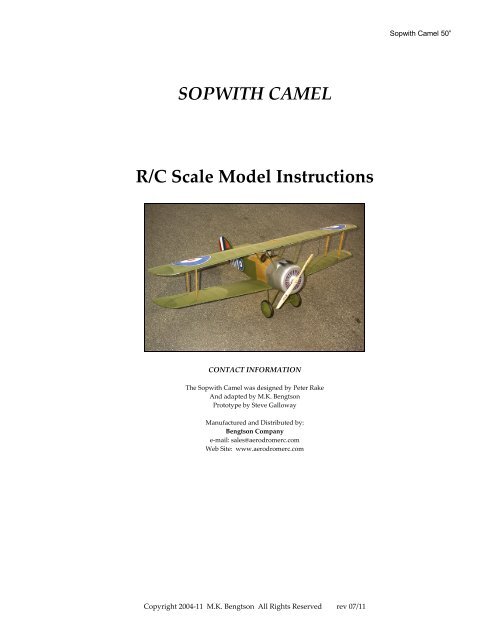
<strong>SOPWITH</strong> <strong>CAMEL</strong><br />
R/C <strong>Scale</strong> <strong>Model</strong> <strong>Instructions</strong><br />
CONTACT INFORMATION<br />
The Sopwith Camel was designed by Peter Rake<br />
And adapted by M.K. Bengtson<br />
Prototype by Steve Galloway<br />
Manufactured and Distributed by:<br />
Bengtson Company<br />
e‐mail: sales@aerodromerc.com<br />
Web Site: www.aerodromerc.com<br />
Copyright 2004‐11 M.K. Bengtson All Rights Reserved rev 07/11
Sopwith Camel<br />
Thank you for purchasing the Sopwith Camel model for<br />
electric flight.<br />
THE MODEL<br />
A 50” span, electric powered scale model superbly built and<br />
test flown by Steve Galloway from a design by Peter Rake.<br />
Sopwith Camel 50”<br />
the bottom ailerons. It is also a viable option to fit torque<br />
rods to the bottom ailerons, and fit a single servo into the<br />
fuselage.<br />
Probably the second most famous fighter of WW1, the<br />
Camel is only eclipsed by the Fokker Triplane in terms of<br />
renown. Despite the fact that the Camel was probably the<br />
better fighter aircraft. A type both loved, and feared, by<br />
modellers, this little model demonstrates none of the bad<br />
habits that earned the full size machine such a reputation for<br />
killing novice pilots.<br />
<strong>Model</strong> Specifications<br />
More than 230 laser cut parts<br />
<strong>Scale</strong>: ~1/7 th<br />
Channels: R/E/A/T<br />
Wingspan: 50ʺ<br />
Wing Area: 740 Sq. in<br />
Weight: 64 Oz.<br />
Power System: Speed 600BB power w 2.3:1 gear box1<br />
Prop: 14x7 prop<br />
Covering: Balsa and Litespan or Polyspan covering<br />
Wheels: Balsa & plywood, Neoprene foam tires<br />
Cowl: Built up balsa and plywood/<br />
Spinner: N/A/<br />
The top wing of your model is attached to the centre section<br />
struts using four saddle clamps, bent up from brass or<br />
aluminium strip, screwed to the ply plates in the wing. The<br />
bottom wing panels use dowels to help locate them at the<br />
correct incidence angle, and are securely glued in place. The<br />
interplane struts determine the dihedral angle of the bottom<br />
wings, but the top wing has NO dihedral at all. A root rib<br />
angle of approximately 4.5‐5 degrees is required on the<br />
bottom wings to allow for the dihedral.<br />
TOP WING<br />
WINGS<br />
The Sopwith Camel has ailerons on all four wing panels, so<br />
does this model. Unlike the original, where all four ailerons<br />
were operated by a closed loop system of control wires, the<br />
model uses two servos let into the bottom wings. It is very<br />
important that you use the smallest, thinnest servos you can<br />
get, commensurate with the loads to be placed on them. The<br />
extension leads are led into the fuselage through the wing<br />
roots and the servos operate the bottom ailerons via<br />
pushrods. The top ailerons are operated by link rods from<br />
Notch the trailing edge to accept the ribs and pin down the<br />
trailing edge, spars, leading edge and wing tip over the plan<br />
– glue as required. Add the ply centre braces. Trim the ribs<br />
for the aileron area, and glue the ribs in place. This includes<br />
the notched and gusseted 1/8 ply ribs that the interplane<br />
struts fit into. Measure the position of the notches from the<br />
view of the composite rib. Glue the wing cut out pieces in<br />
place and glue the balsa false trailing edge against the rear<br />
spar and wingtip at the aileron position. Pin in position, but<br />
DO NOT GLUE, the aileron leading edge in place against the<br />
false trailing edge. Fit the aileron ribs, horn plate and ply<br />
wing mount plates before leaving to dry. Now repeat for the<br />
opposite wing panel and then join the wings ensuring they<br />
align correctly and are FLAT. Once dry, add the centre<br />
Copyright 2004‐11 M.K. Bengtson All Rights Reserved rev 07/11
section sheeting. Remove from board and trim and sand to<br />
shape. Cut the ailerons away from the main panels and<br />
round off the leading edge as shown. Fit horns after<br />
covering, only link horns being fitted to the top wing<br />
ailerons (lower surface).<br />
Sopwith Camel 50”<br />
BOTTOM WINGS<br />
Although basically the same procedure as for the top wings<br />
is used, the root rib must be angled for dihedral, and servo<br />
hatch blocks fitted. These should be fitted in such a way that<br />
the servo hatch will sit flush with the lower surface of the<br />
wing. The bottom wing ailerons have both a control horn<br />
(lower surface) and a link horn (upper surface).<br />
TAIL SURFACES<br />
Tail surfaces are built over the plan using 1/8 balsa sheet and<br />
strip. Allow to dry thoroughly before sanding overall and<br />
rounding off all edges. Drill and groove the elevators for the<br />
wire joiner and glue the joiner firmly in place. Once again,<br />
control horns are fitted after covering.<br />
REAR BOX<br />
Build two identical side frames over the plan using balsa<br />
strip and allow to dry completely. Score each frame on the<br />
inside, at the point indicated, and crack. Make sure you<br />
produce one right and one left side. Join the sides, over the<br />
plan, with the cross braces and tail skid plate. Work plenty<br />
of glue into the cracked areas and join the tail. Check that the<br />
assembly is straight and square before allowing to dry. Then<br />
glue in place the tail bay fill pieces, paying particular<br />
attention to the glue joint at the rear upright immediately in<br />
front of the crack. Set the assembly to one side.<br />
FRONT BOX<br />
Bind and epoxy the centre section strut wires to F1B and F2.<br />
Although both wires are the same size, only the front one<br />
has a bend rearwards. Join the sides using formers F1A,F1B,<br />
F2, F3, F4 and F5. Check that the structure is square and that<br />
the centre section struts are correctly aligned before allowing<br />
to dry. Glue in place motor mount parts M1 and M2, and the<br />
cockpit floor.<br />
WHOLE FUSELAGE<br />
FUSELAGE<br />
The fuselage is constructed as two separate box structures,<br />
the front, sheet one, and the rear, built up one. These are<br />
then joined over the plan before any decking formers are<br />
added. Although this deviates from scale slightly, it does<br />
assist with building a straight fuselage.<br />
Join the front and rear fuselage assemblies over the plan as a<br />
guide to alignment, check for square and allow to dry. Fit<br />
formers F1C,F2A and F3A, followed by the balsa decking,<br />
and fit the section of block balsa that makes up the front of<br />
the ‘hump’. Because of the changes in section of the decking,<br />
Copyright 2004‐11 M.K. Bengtson All Rights Reserved rev 07/11
it is best fitted in three steps. Fit each side piece first, cut<br />
pieces to cover the centre areas and use those as a guide for<br />
trimming the side pieces, prior to gluing on the centres. Trim<br />
the cockpit opening to shape once the sheeting is dry. Now<br />
fit Formers F1D and the side sheeting. Once dry, use the<br />
bottom wing panels to mark out the area that needs to be<br />
removed to allow the wings to seat against the fuselage<br />
sides. Fit the lower sheet fill pieces between the sides,<br />
followed by the rear formers and stringers. Use an<br />
accurately aligned cowl former to mark out the shape that<br />
the block area needs to be, then trim and sand the fuselage.<br />
Do not be too enthusiastic on the block area, that can be<br />
finish sanded once you have a cowl in place.<br />
U/C<br />
Sopwith Camel 50”<br />
COWL<br />
Bind the undercarriage wires to formers F4 and F5, bind and<br />
solder the wires to the axle and then glue the top bindings.<br />
Alternatively, the u/c may be retained using saddle clamps<br />
and screws<br />
If desired, a more scale like appearance may be achieved by<br />
adding scrap balsa fairings to the wires and then wrapping<br />
with covering material prior to painting.<br />
Wrap the 1/32 ply strip around one former C1, gluing as you<br />
proceed and then add the other C1. Glue in place the C2<br />
laminations and allow to dry. Trim the rear of the cowl as<br />
indicated on the plan, trim and sand the front of the cowl<br />
and then seal and sand very smooth ready for painting.<br />
COVERING AND FINISHING<br />
Any of the lightweight coverings such as Litespan or doped<br />
Polyspan are ideal for this model. The nose areas are<br />
covered with a chrome finish film that has been rubbed<br />
down with fine sand paper and steel wool to give it a<br />
burnished metal appearance.<br />
A simple cowl fixing may be made by making two L shaped<br />
brackets from scrap material. The top of the rearmost C1<br />
hooks into them, and two small screws retain the bottom.<br />
Screwdriver access is through the open font of the cowl.<br />
Copyright 2004‐11 M.K. Bengtson All Rights Reserved rev 07/11
INSTALLATION<br />
Sopwith Camel 50”<br />
Details such as the pilot and dummy engine, which does not<br />
actually rotate with the prop, are simply printed images<br />
stuck to light support frames. They do, however, look most<br />
effective.<br />
ASSEMBLY<br />
First accurately align the fuselage, upside down over the top<br />
wing, and mark the saddle clamp screw positions. Drill the<br />
holes and clamp the top wing to the centre section struts. Fit<br />
the bottom wing panels next, using the locating dowels and<br />
interplane struts to set both incidence and dihedral. Also<br />
ensure that they align accurately with the fuselage/top wing<br />
before allowing to dry. Use this assembly as a guide to<br />
accuracy while gluing in place the ready hinged tail surfaces.<br />
Ensure that the covering has been trimmed away in all glue<br />
joint areas.<br />
The motor unit, a Graupner S600BB, 2.33:1,is simply screwed<br />
to the motor plate. Closed loop linkage for the rudder, not<br />
shown on the plan but essential for scale effect is used. The<br />
weight saving over a pushrod is obvious.<br />
With the radio gear thus positioned, the model balanced<br />
almost perfectly at the point indicated, thereby allowing the<br />
battery pack, 8x1950 cells, to be placed below the balance<br />
point. A very useful situation if you want to use more than<br />
one style and size of pack.<br />
Copyright 2004‐11 M.K. Bengtson All Rights Reserved rev 07/11
FLYING<br />
Sopwith Camel 50”<br />
The model files well. The ailerons work well, with a 70/30<br />
differential, but adding in some rudder makes turns that<br />
much smoother – just as with most biplanes of this style.<br />
Let the model gain altitude slowly off the runway. Applying<br />
too much up elevator at slow speeds asks for a stall. Make<br />
your turns gently as tight turns risk tip stalling in any<br />
model. Don’t expect the elevator to make the model climb.<br />
Think of the elevator as a device to change the attitude of the<br />
model. The wing and airspeed ultimately make the model<br />
climb. Often down elevator applied at stalling can avoid a<br />
major crash. The most important details for proper flight<br />
operations are:<br />
1) CG location. Tail‐heavy models never fly well or at all.<br />
2) Down and right thrust<br />
3) Straight and non‐warped wings.<br />
4) Be sure you assemble and lube the gearbox so that it is<br />
not binding. A binding gearbox will rob most of your<br />
batteries power.<br />
CONTACT INFORMATION<br />
Distributed by:<br />
Bengtson Company<br />
e‐mail: sales@<strong>AerodromeRC</strong>.com<br />
Web Site: www.<strong>AerodromeRC</strong>.com<br />
Copyright 2004‐11 M.K. Bengtson All Rights Reserved rev 07/11