7060 Offshore Kit.qxd - Balmar
7060 Offshore Kit.qxd - Balmar
7060 Offshore Kit.qxd - Balmar

You also want an ePaper? Increase the reach of your titles
YUMPU automatically turns print PDFs into web optimized ePapers that Google loves.
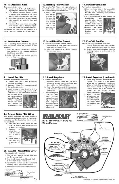
15. Re-Assemble Case<br />
To re-assemble the case:<br />
1. Insert rotor shaft through the front bearing<br />
and press until bearing is seated.<br />
2. Slide the rear case onto the rear portion<br />
of the rotor assembly. Ensure that stator<br />
wires extend properly through the case.<br />
3. Maintain pressure until the bearings and<br />
rotor assembly are seated in front and<br />
rear cases<br />
4. Insert the four case mount bolts, align<br />
front and rear cases to their proper positions<br />
and tighten the case mount bolts.<br />
Ensure that the case bolts are tightened in a<br />
uniform manner to ensure proper alignment.<br />
16. Isolating Fiber Washer<br />
The isolating Fiber Washer (#4 in parts list) must<br />
be installed on the alternator before installing the<br />
brushholder or regulator assemblies:<br />
1. Place the<br />
fiber washer<br />
included in<br />
the repair kit<br />
on the bolt<br />
hole located<br />
on the rear<br />
case of the<br />
alternator.<br />
See photo.<br />
17. Install Brushholder<br />
To install the brushholder:<br />
1. Slide the slotted tabs of the brushholder<br />
base around the rear bearing and rear of<br />
the rotor shaft. Temporarily install Torx bolt<br />
to ensure alignment.<br />
2. Tap the brushholder in place. Ensure the<br />
brushholder stays<br />
straight when tapped<br />
into position. Fiber<br />
washer must stay in<br />
position under bolt hole.<br />
3. Remove the brush<br />
retainer ring to seat<br />
brushes on rotor<br />
sleeves.<br />
18. Brushholder Ground<br />
Prior to installing the brushholder, the ground<br />
wire connection should be soldered to the<br />
assembly:<br />
1. Insert ground wire (without ring terminal)<br />
into the notch in the negative tab of the<br />
brushholder assembly.<br />
2. Using high-temperature solder, fuse the<br />
wire to the ground tab.<br />
19. Install Rectifier Gasket<br />
To install the replacement rectifier gasket:<br />
1. Place gasket on bare metal portion of the<br />
rear case, as shown below.<br />
2. Align bolt holes with pre-drilled holes in<br />
the alternator case.<br />
20. Pre-Drill Rectifier<br />
Prior to installing the rectifier assembly:<br />
1. Insert a step drill into the bolt hole neares<br />
the rectifier’s ground post. See photo.<br />
2. Enlarge hole enough to allow the white<br />
isolating washer to be inserted in the<br />
bolt hole.<br />
21. Install Rectifier<br />
To install the replacement rectifier:<br />
1. Connect main ground wire terminal to<br />
regulator ground stud.<br />
2. Insert and tighten Torx bolt at center of<br />
the rectifier assembly.<br />
3. Insert contoured ring terminal in the<br />
ground wire harness (ring terminal is offset<br />
to allow the ground wire to fit between<br />
the rectifier plate<br />
and the brushholder<br />
assembly) under the<br />
white insulating<br />
washer, and insert<br />
and tighten the<br />
remaining Torx bolt.<br />
22. Install Regulator<br />
To complete the installation:<br />
1. Place the regulator on the rear case of the<br />
alternator, with the bolt holes aligned with<br />
the rectifier and the brushholder.<br />
2. Insert the tab at the end of the regulator<br />
with the crimp tabs on the rectifier. Crimp<br />
and solder.<br />
3. Insert and tighten<br />
Torx bolt with<br />
short isolating<br />
washer in mounting<br />
hole furthest<br />
from regulator<br />
plug (leave loose<br />
enough for minor<br />
adjustment).<br />
23. Install Regulator (continued)<br />
4. Place ring terminal connections for<br />
ground and 100-ohm (D+) resistor<br />
wires, and star washer on the underside<br />
of the white isolater and push into bolt<br />
hole marked GND on regulator. Star<br />
washer should be at the bottom as<br />
shown in the wiring diagram<br />
below.Insert and tighten Torx bolt.<br />
5. Wrap ground<br />
wires around outside<br />
of brushholder<br />
to avoid pinching<br />
wires when<br />
re-installing rear<br />
cover.<br />
24. Attach Stator / D+ Wires<br />
The rectifier assembly has three terminals<br />
required to provide connection to the alternator’s<br />
stator and D+ circuit wires. After the rectifier<br />
is installed:<br />
1. Place the three stator wires and the<br />
three D+ wires in their crimp terminals<br />
as shown in the photo.<br />
2. Squeeze the<br />
crimp tabs to<br />
hold the stator<br />
and D+ wires in<br />
place.<br />
3. Solder wires in<br />
place with hightemperature<br />
solder.<br />
Model <strong>7060</strong> <strong>Offshore</strong> Parts <strong>Kit</strong><br />
Wiring Diagram<br />
25. Install D+ Circuit/Rear Cover<br />
To re-install the D+ terminal:<br />
1. Slip 100 ohm resistor ring terminal onto<br />
the D+ terminal stud.<br />
2. Insert the D+terminal stud through the D+<br />
terminal hole in rear case cover.<br />
3. Re-install flat washers (2), star washer and<br />
retaining nut on outside of rear cover.<br />
4. Snap rear case cover onto alternator case.<br />
© Copyright 2006 Ballard Commercial Industries, Inc.