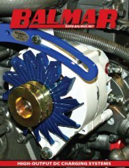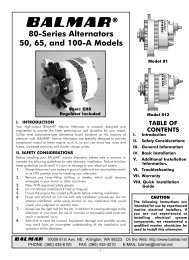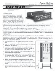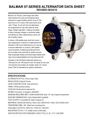
7060 Offshore Kit.qxd - Balmar
7060 Offshore Kit.qxd - Balmar
7060 Offshore Kit.qxd - Balmar

Create successful ePaper yourself
Turn your PDF publications into a flip-book with our unique Google optimized e-Paper software.
Model <strong>7060</strong> Alternator<br />
12-Volt <strong>Offshore</strong> Parts <strong>Kit</strong><br />
Installation Instructions<br />
Professional Installation Is Required<br />
START HERE<br />
1. <strong>Kit</strong> Compatibility<br />
The Model <strong>7060</strong> Alternator <strong>Offshore</strong> Parts <strong>Kit</strong> is<br />
intended for use with the following 12-volt<br />
alternator models:<br />
Model:<br />
Model:<br />
Model:<br />
60-70-SR-IG<br />
60-100-SR-IG<br />
60-120-SR-IG<br />
60-150-SR-IG<br />
621-70-SR-IG<br />
621-100-SR-IG<br />
621-120-SR-IG<br />
621-150-SR-IG<br />
604-120-SR-IG<br />
604-150-SR-IG<br />
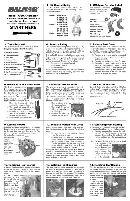
2. <strong>Offshore</strong> Parts Included<br />
The offshore replacement<br />
parts included with the<br />
Model <strong>7060</strong> <strong>Offshore</strong><br />
Parts <strong>Kit</strong> are:<br />
3<br />
1. Regulator<br />
2. Brush Holder Assembly<br />
3. Rear Bearing<br />
4. Regulator Washer<br />
5. Rectifier Assembly<br />
6. Rectifier Gasket<br />
7. Front Bearing<br />
8. Instruction Sheet (Not Shown)<br />
5<br />
4<br />
2<br />
7<br />
1<br />
6<br />
3. Tools Required<br />
The following tools will be required to install<br />
the parts included in the <strong>Offshore</strong> <strong>Kit</strong>:<br />
1. Adjustable Wrench<br />
2. Flat Head Screwdriver<br />
3. Wire Cutter<br />
4. Needlenose Plier<br />
5. Allen Wrench Set<br />
6. Rachet / Deep Well Socket Set<br />
7. Non-Marring Mallet<br />
8. Heavy Duty Gear Puller<br />
9. High Temperature Soldering Iron<br />
10. E-5 Torx Socket/Driver<br />
4. Remove Pulley<br />
The 6-Series alternator’s pulley is held in place by<br />
a nut and lockwasher. A hexagonal indent is provided<br />
in the end of the pulley shaft, should it be<br />
necessary to remove the nut with hand tools.<br />
It is preferable to use an electrical or pneumatic<br />
impact wrench to remove the pulley nut from the<br />
pulley shaft. A 15/16” or 24mm impact wrench<br />
socket is required. To remove the pulley:<br />
1. Loosen and remove pulley nut.<br />
2. Remove lock washer.<br />
3. Remove pulley.<br />
During disassembly, keep parts separated and in<br />
order to ensure they are properly replaced when<br />
the alternator is re-assembled.<br />
5. Remove Rear Cover<br />
The black plastic case at the rear of the alternator<br />
provides access to the rectifier assembly,<br />
brushholder assembly and Smart Ready internal<br />
regulator. To remove the rear cover:<br />
1. Remove any wires or cables connected<br />
to the alternator’s positive or negative<br />
output terminals.<br />
2. Remove nut and washers from D+ stud.<br />
3. Carefully pry the plastic retainer tabs<br />
away from the alternator case to allow<br />
the rear case cover to be released from<br />
the alternator case. Be sure that the D+<br />
terminal assembly is free from the cover<br />
before fully removing cover.<br />
6. De-Solder Stator & D+ Wires<br />
The 3 wires supplying the<br />
D+ terminal on the rear<br />
cover of the alternator must<br />
be de-soldered prior to<br />
removal. A high-temperature<br />
iron like that shown<br />
below must be used, as<br />
high-temperature solder is used.<br />
1. Heat wire terminal at rectifier<br />
until solder becomes fluid.<br />
2. Use small flat screwdriver to<br />
carefully pry terminal open.<br />
3. Remove D+ wire and stator<br />
wire from terminal jaws and<br />
remove excess solder.<br />
4. Repeat at remaining terminals.<br />
High-Temp Soldering Iron<br />
7. De-Solder Ground Wires<br />
The alternator’s ground is connected to the rectifier,<br />
regulator and brushholder assemblies via a<br />
three-wire connector that attaches to the alternator’s<br />
ground terminal stud. One of the three wire<br />
leads is soldered to the brushholder assembly.<br />
The remaining wires are connected to the rectifier<br />
and regulator with ring terminals. To remove<br />
the brushholder wire:<br />
1. Heat wire terminal at brushholder until solder<br />
becomes fluid.<br />
2. Use small flat screwdriver<br />
to carefully pry<br />
terminal open.<br />
3. Remove B- wire and<br />
remove excess solder.<br />
8. D+ Circuit Resistor<br />
Some 6-Series alternators include a 100 ohm<br />
resistor that’s mounted between the regulator<br />
ground terminal and the alternator’s D+ terminal.<br />
The resistor must be re-installed on the<br />
same connection points when replacement<br />
parts are installed.<br />
9. Remove Screws<br />
Four E-5 Torx head screws secure the rectifier,<br />
brushholder and internal regulator assemblies<br />
to the rear alternator case. Remove the Torx<br />
screws indicated in the illustration below.<br />
When the four screws are<br />
removed, the<br />
regulator and<br />
rectifier<br />
assemblies<br />
can be<br />
removed<br />
from the<br />
back of the<br />
alternator<br />
case.<br />
10. Separate Front & Rear Cases<br />
Once the rear assemblies have been removed,<br />
the alternator case can be opened. To split the<br />
case:<br />
1. Remove the stator wire isolating retainer<br />
from the wires and save.<br />
2. Carefully pry the front and rear cases<br />
apart, using care to ensure the cases are<br />
spread evenly around their perimeters.<br />
The humps where the the four case bolt<br />
holes extend through the front and rear<br />
cases provide optimal pry points.<br />
Note: The stator and front bearing will typically<br />
remain in the faceplate when the case is opened.<br />
The rear bearing may remain on the rotor shaft or<br />
in the brushholder assembly. The following steps<br />
describe bearing removal.<br />
11. Removing Front Bearing<br />
We strongly recommend the use of a press to<br />
remove the front bearing from the faceplate.<br />
1. Place the faceplate face up on a flat working<br />
surface. Provide support under the<br />
faceplate (surrounding the underside of<br />
the bearing) to ensure the faceplate does<br />
not crack.<br />
2. If a press is not available, use a dead<br />
blow hammer and<br />
deep well socket, to<br />
tap the bearing out<br />
of the faceplate. Use<br />
care to ensure that<br />
the bearing is tapped<br />
evenly to avoid damage<br />
to the faceplate.<br />
12. Removing Rear Bearing<br />
If the rear bearing remains on the rotor shaft as<br />
shown in the photo below, a puller may be<br />
required to remove the bearing for replacement.<br />
If the bearing<br />
remains in the<br />
brushholder<br />
assembly, the<br />
bearing and brushhholder<br />
may both<br />
be removed by<br />
tapping the bearing<br />
out from the<br />
inside of the rear<br />
alternator case.<br />
13. Installing Front Bearing<br />
The front bearing can be pressed in, or tapped in<br />
by hand if a press is unavailable. See photos<br />
below. Use care to ensure that the bearing is<br />
inserted squarely into the faceplate. The bearing<br />
can be chilled prior to installation to reduce force<br />
required to seat the bearing when installing.<br />
14. Installing Rear Bearing<br />
Slip the rear bearing over the rear end of the<br />
rotor shaft. The bearing will slide past the positive<br />
and negative rotor sleeves and will seat just<br />
shy of the rear rotor fan. A deep well socket<br />
works well to<br />
drive the bearing<br />
in place.<br />
Chilling the rear<br />
bearing prior to<br />
installation will<br />
reduce force<br />
required to properly<br />
seat the<br />
bearing on the<br />
rotor shaft.
15. Re-Assemble Case<br />
To re-assemble the case:<br />
1. Insert rotor shaft through the front bearing<br />
and press until bearing is seated.<br />
2. Slide the rear case onto the rear portion<br />
of the rotor assembly. Ensure that stator<br />
wires extend properly through the case.<br />
3. Maintain pressure until the bearings and<br />
rotor assembly are seated in front and<br />
rear cases<br />
4. Insert the four case mount bolts, align<br />
front and rear cases to their proper positions<br />
and tighten the case mount bolts.<br />
Ensure that the case bolts are tightened in a<br />
uniform manner to ensure proper alignment.<br />
16. Isolating Fiber Washer<br />
The isolating Fiber Washer (#4 in parts list) must<br />
be installed on the alternator before installing the<br />
brushholder or regulator assemblies:<br />
1. Place the<br />
fiber washer<br />
included in<br />
the repair kit<br />
on the bolt<br />
hole located<br />
on the rear<br />
case of the<br />
alternator.<br />
See photo.<br />
17. Install Brushholder<br />
To install the brushholder:<br />
1. Slide the slotted tabs of the brushholder<br />
base around the rear bearing and rear of<br />
the rotor shaft. Temporarily install Torx bolt<br />
to ensure alignment.<br />
2. Tap the brushholder in place. Ensure the<br />
brushholder stays<br />
straight when tapped<br />
into position. Fiber<br />
washer must stay in<br />
position under bolt hole.<br />
3. Remove the brush<br />
retainer ring to seat<br />
brushes on rotor<br />
sleeves.<br />
18. Brushholder Ground<br />
Prior to installing the brushholder, the ground<br />
wire connection should be soldered to the<br />
assembly:<br />
1. Insert ground wire (without ring terminal)<br />
into the notch in the negative tab of the<br />
brushholder assembly.<br />
2. Using high-temperature solder, fuse the<br />
wire to the ground tab.<br />
19. Install Rectifier Gasket<br />
To install the replacement rectifier gasket:<br />
1. Place gasket on bare metal portion of the<br />
rear case, as shown below.<br />
2. Align bolt holes with pre-drilled holes in<br />
the alternator case.<br />
20. Pre-Drill Rectifier<br />
Prior to installing the rectifier assembly:<br />
1. Insert a step drill into the bolt hole neares<br />
the rectifier’s ground post. See photo.<br />
2. Enlarge hole enough to allow the white<br />
isolating washer to be inserted in the<br />
bolt hole.<br />
21. Install Rectifier<br />
To install the replacement rectifier:<br />
1. Connect main ground wire terminal to<br />
regulator ground stud.<br />
2. Insert and tighten Torx bolt at center of<br />
the rectifier assembly.<br />
3. Insert contoured ring terminal in the<br />
ground wire harness (ring terminal is offset<br />
to allow the ground wire to fit between<br />
the rectifier plate<br />
and the brushholder<br />
assembly) under the<br />
white insulating<br />
washer, and insert<br />
and tighten the<br />
remaining Torx bolt.<br />
22. Install Regulator<br />
To complete the installation:<br />
1. Place the regulator on the rear case of the<br />
alternator, with the bolt holes aligned with<br />
the rectifier and the brushholder.<br />
2. Insert the tab at the end of the regulator<br />
with the crimp tabs on the rectifier. Crimp<br />
and solder.<br />
3. Insert and tighten<br />
Torx bolt with<br />
short isolating<br />
washer in mounting<br />
hole furthest<br />
from regulator<br />
plug (leave loose<br />
enough for minor<br />
adjustment).<br />
23. Install Regulator (continued)<br />
4. Place ring terminal connections for<br />
ground and 100-ohm (D+) resistor<br />
wires, and star washer on the underside<br />
of the white isolater and push into bolt<br />
hole marked GND on regulator. Star<br />
washer should be at the bottom as<br />
shown in the wiring diagram<br />
below.Insert and tighten Torx bolt.<br />
5. Wrap ground<br />
wires around outside<br />
of brushholder<br />
to avoid pinching<br />
wires when<br />
re-installing rear<br />
cover.<br />
24. Attach Stator / D+ Wires<br />
The rectifier assembly has three terminals<br />
required to provide connection to the alternator’s<br />
stator and D+ circuit wires. After the rectifier<br />
is installed:<br />
1. Place the three stator wires and the<br />
three D+ wires in their crimp terminals<br />
as shown in the photo.<br />
2. Squeeze the<br />
crimp tabs to<br />
hold the stator<br />
and D+ wires in<br />
place.<br />
3. Solder wires in<br />
place with hightemperature<br />
solder.<br />
Model <strong>7060</strong> <strong>Offshore</strong> Parts <strong>Kit</strong><br />
Wiring Diagram<br />
25. Install D+ Circuit/Rear Cover<br />
To re-install the D+ terminal:<br />
1. Slip 100 ohm resistor ring terminal onto<br />
the D+ terminal stud.<br />
2. Insert the D+terminal stud through the D+<br />
terminal hole in rear case cover.<br />
3. Re-install flat washers (2), star washer and<br />
retaining nut on outside of rear cover.<br />
4. Snap rear case cover onto alternator case.<br />
© Copyright 2006 Ballard Commercial Industries, Inc.