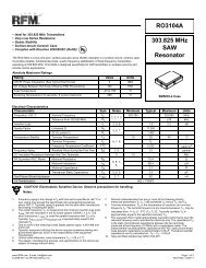
433.92 MHz SAW Resonator RO3101A - RF Monolithics, Inc.
433.92 MHz SAW Resonator RO3101A - RF Monolithics, Inc.
433.92 MHz SAW Resonator RO3101A - RF Monolithics, Inc.

Create successful ePaper yourself
Turn your PDF publications into a flip-book with our unique Google optimized e-Paper software.
Case Ground<br />
Case Ground<br />
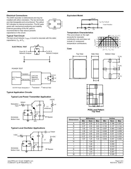
Electrical Connections<br />
The <strong>SAW</strong> resonator is bidirectional and may be<br />
Terminal<br />
installed with either orientation. The two terminals<br />
are interchangeable and unnumbered. The callout<br />
NC indicates no internal connection. The NC pads<br />
assist with mechanical positioning and stability.<br />
External grounding of the NC pads is<br />
Terminal<br />
recommended to help reduce parasitic<br />
capacitance in the circuit.<br />
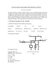
Typical Test Circuit<br />
The test circuit inductor, L TEST , is tuned to resonate with the static<br />
capacitance, C O , at F C .<br />
ELECTRICAL TEST<br />
From 50 Ω<br />
Network Analyzer<br />
To 50 Ω<br />
Network Analyzer<br />
Equivalent Model<br />
Temperature Characteristics<br />
The curve shown on the right<br />
accounts for resonator<br />
contribution only and does not<br />
include LC component<br />
temperature contributions.<br />
Case<br />
0.05 pF*<br />
Cp<br />
Rm Lm C m<br />
(f-f o )/ f o (ppm)<br />
)<br />
0<br />
-50<br />
-100<br />
-150<br />
Co = Cp + 0.05 pF<br />
*Case Parasitics<br />
-200<br />
-80 -60 -40 -20 0 +20 +40 +60<br />
∆T = T C - T O ( °C )<br />
6 F 8 EA M 5 E@ A 8 EA M * JJ 8 EA M<br />
* +<br />
f C = f O , T C = T O<br />
0<br />
-50<br />
-100<br />
-150<br />
-200<br />
+80<br />
- ! N <br />
"<br />
POWER TEST<br />
!<br />
<br />
. " N <br />
50 Ω Source<br />
at F C<br />
P<br />
INCIDENT<br />
P<br />
REFLECTED<br />
Low-Loss<br />
Matching<br />
Network to<br />
50 Ω<br />
NC<br />
Terminal<br />
NC<br />
Terminal<br />
,<br />
/ N <br />
CW <strong>RF</strong> Power Dissipation = P INCIDENT - P REFLECTED<br />
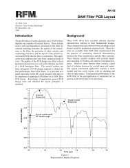
Typical Application Circuits<br />
Typical Low-Power Transmitter Application<br />
Modulation<br />
Input<br />
RO3XXXA<br />
Bottom View<br />
+VDC<br />
200kΩ<br />
C1<br />
470<br />
C2<br />
C1<br />
C2<br />
Typical Local Oscillator Applications<br />
RO3XXXA<br />
Bottom View<br />
L1<br />
(Antenna)<br />
L1<br />
+9VDC<br />
<strong>RF</strong> Bypass<br />
Output<br />
<strong>RF</strong> Bypass<br />
47<br />
+VDC<br />
0<br />
1<br />
<br />
<br />
<br />
0 0<br />
PCB Land Pattern<br />
Top View<br />
Dimensions<br />
Millimeters<br />
<strong>Inc</strong>hes<br />
Min Nom Max Min Nom Max<br />
A 4.87 5.00 5.13 0.191 0.196 0.201<br />
B 3.37 3.50 3.63 0.132 0.137 0.142<br />
C 1.45 1.53 1.60 0.057 0.060 0.062<br />
D 1.35 1.43 1.50 0.040 0.057 0.059<br />
E 0.67 0.80 0.93 0.026 0.031 0.036<br />
F 0.37 0.50 0.63 0.014 0.019 0.024<br />
G 1.07 1.20 1.33 0.042 0.047 0.052<br />
H - 1.04 - - 0.041 -<br />
I - 1.46 - - 0.058 -<br />
J - 0.50 - - 0.019 -<br />
K - 1.05 - - 0.041 -<br />
L - 1.44 - - 0.057 -<br />
M - 0.71 - - 0.028 -<br />
www.<strong>RF</strong>M.com E-mail: info@rfm.com Page 2 of 2<br />
© 2008-2011 by <strong>RF</strong> <strong>Monolithics</strong>, <strong>Inc</strong>. <strong>RO3101A</strong> - 6/28/11