433.92 MHz SAW Resonator RO3101A - RF Monolithics, Inc.
433.92 MHz SAW Resonator RO3101A - RF Monolithics, Inc.
433.92 MHz SAW Resonator RO3101A - RF Monolithics, Inc.

Create successful ePaper yourself
Turn your PDF publications into a flip-book with our unique Google optimized e-Paper software.
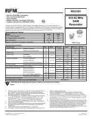
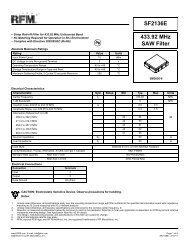
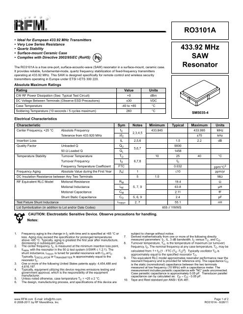
• Ideal for European <strong>433.92</strong> <strong>MHz</strong> Transmitters<br />
• Very Low Series Resistance<br />
• Quartz Stability<br />
• Surface-mount Ceramic Case<br />
• Complies with Directive 2002/95/EC (RoHS)<br />
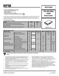
The <strong>RO3101A</strong> is a true one-port, surface-acoustic-wave (<strong>SAW</strong>) resonator in a surface-mount, ceramic case.<br />
It provides reliable, fundamental-mode, quartz frequency stabilization of fixed-frequency transmitters<br />
operating at <strong>433.92</strong> <strong>MHz</strong>. This <strong>SAW</strong> is designed specifically for remote control and wireless security<br />
transmitters operating in Europe under ETSI I-ETS 300 220.<br />
Absolute Maximum Ratings<br />
Rating Value Units<br />
CW <strong>RF</strong> Power Dissipation (See: Typical Test Circuit) +0 dBm<br />
DC Voltage Between Terminals (Observe ESD Precautions) ±30 VDC<br />
Case Temperature -40 to +85 °C<br />
Soldering Temperature (10 seconds / 5 cycles maximum) 260 °C<br />
Electrical Characteristics<br />
Characteristic Sym Notes Minimum Typical Maximum Units<br />
Center Frequency, +25 °C Absolute Frequency f C 433.845 433.995 <strong>MHz</strong><br />
2,3,4,5<br />
Tolerance from <strong>433.92</strong>0 <strong>MHz</strong> ∆f C ±75 kHz<br />
Insertion Loss IL 2,5,6 1.5 2.2 dB<br />
Quality Factor Unloaded Q Q U 9000<br />
5,6,7<br />
50 Ω Loaded Q Q L 1458<br />
Temperature Stability Turnover Temperature T O 10 25 40 °C<br />
Turnover Frequency f O 6,7,8<br />
f C<br />
Frequency Temperature Coefficient FTC 0.032 ppm/°C 2<br />
Frequency Aging Absolute Value during the First Year |f A | 1 ≤10 ppm/yr<br />
DC Insulation Resistance between Any Two Terminals 5 1.0 MΩ<br />
<strong>RF</strong> Equivalent RLC Model Motional Resistance R M 19.4 Ω<br />
Motional Inductance L M 5, 7, 9<br />
63.8 µH<br />
Motional Capacitance C M 2.11 fF<br />
Shunt Static Capacitance C O 5, 6, 9 2.4 pF<br />
Test Fixture Shunt Inductance L TEST 2, 7 55.1 nH<br />
Lid Symbolization (in addition to Lot and/or Date Codes)<br />
Pb<br />
CAUTION: Electrostatic Sensitive Device. Observe precautions for handling.<br />
Notes:<br />
655 // YWWS<br />
<strong>RO3101A</strong><br />
<strong>433.92</strong> <strong>MHz</strong><br />
<strong>SAW</strong><br />
<strong>Resonator</strong><br />
SM5035-4<br />
1. Frequency aging is the change in f C with time and is specified at +65 °C or<br />
less. Aging may exceed the specification for prolonged temperatures<br />
above +65 °C. Typically, aging is greatest the first year after manufacture,<br />
decreasing in subsequent years.<br />
2. The center frequency, f C , is measured at the minimum insertion loss point,<br />
IL MIN , with the resonator in the 50 Ω test system (VSWR ≤ 1.2:1). The<br />
shunt inductance, L TEST , is tuned for parallel resonance with C O at f C .<br />
Typically, f OSCILLATOR or f TRANSMITTER is approximately equal to the<br />
resonator f C .<br />
3. One or more of the following United States patents apply: 4,454,488 and<br />
4,616,197.<br />
4. Typically, equipment utilizing this device requires emissions testing and<br />
government approval, which is the responsibility of the equipment<br />
manufacturer.<br />
5. Unless noted otherwise, case temperature T C =+25 ± 2 °C.<br />
6. The design, manufacturing process, and specifications of this device are<br />
subject to change without notice.<br />
7. Derived mathematically from one or more of the following directly<br />
measured parameters: f C , IL, 3 dB bandwidth, f C versus T C , and C O .<br />
8. Turnover temperature, T O , is the temperature of maximum (or turnover)<br />
frequency, f O . The nominal frequency at any case temperature, T C , may be<br />
calculated from: f = f O [1 - FTC (T O -T C ) 2 ]. Typically oscillator T O is<br />
approximately equal to the specified resonator T O .<br />
9. This equivalent RLC model approximates resonator performance near the<br />
resonant frequency and is provided for reference only. The capacitance C O<br />
is the static (nonmotional) capacitance between the two terminals<br />
measured at low frequency (10 <strong>MHz</strong>) with a capacitance meter. The<br />
measurement includes parasitic capacitance with "NC” pads unconnected.<br />
Case parasitic capacitance is approximately 0.05 pF. Transducer parallel<br />
capacitance can by calculated as: C P ≈ C O -0.05pF.<br />
10. Tape and Reel standard per ANSI / EIA 481.<br />
www.<strong>RF</strong>M.com E-mail: info@rfm.com Page 1 of 2<br />
© 2008-2011 by <strong>RF</strong> <strong>Monolithics</strong>, <strong>Inc</strong>. <strong>RO3101A</strong> - 6/28/11
Case Ground<br />
Case Ground<br />
Electrical Connections<br />
The <strong>SAW</strong> resonator is bidirectional and may be<br />
Terminal<br />
installed with either orientation. The two terminals<br />
are interchangeable and unnumbered. The callout<br />
NC indicates no internal connection. The NC pads<br />
assist with mechanical positioning and stability.<br />
External grounding of the NC pads is<br />
Terminal<br />
recommended to help reduce parasitic<br />
capacitance in the circuit.<br />
Typical Test Circuit<br />
The test circuit inductor, L TEST , is tuned to resonate with the static<br />
capacitance, C O , at F C .<br />
ELECTRICAL TEST<br />
From 50 Ω<br />
Network Analyzer<br />
To 50 Ω<br />
Network Analyzer<br />
Equivalent Model<br />
Temperature Characteristics<br />
The curve shown on the right<br />
accounts for resonator<br />
contribution only and does not<br />
include LC component<br />
temperature contributions.<br />
Case<br />
0.05 pF*<br />
Cp<br />
Rm Lm C m<br />
(f-f o )/ f o (ppm)<br />
)<br />
0<br />
-50<br />
-100<br />
-150<br />
Co = Cp + 0.05 pF<br />
*Case Parasitics<br />
-200<br />
-80 -60 -40 -20 0 +20 +40 +60<br />
∆T = T C - T O ( °C )<br />
6 F 8 EA M 5 E@ A 8 EA M * JJ 8 EA M<br />
* +<br />
f C = f O , T C = T O<br />
0<br />
-50<br />
-100<br />
-150<br />
-200<br />
+80<br />
- ! N <br />
"<br />
POWER TEST<br />
!<br />
<br />
. " N <br />
50 Ω Source<br />
at F C<br />
P<br />
INCIDENT<br />
P<br />
REFLECTED<br />
Low-Loss<br />
Matching<br />
Network to<br />
50 Ω<br />
NC<br />
Terminal<br />
NC<br />
Terminal<br />
,<br />
/ N <br />
CW <strong>RF</strong> Power Dissipation = P INCIDENT - P REFLECTED<br />
Typical Application Circuits<br />
Typical Low-Power Transmitter Application<br />
Modulation<br />
Input<br />
RO3XXXA<br />
Bottom View<br />
+VDC<br />
200kΩ<br />
C1<br />
470<br />
C2<br />
C1<br />
C2<br />
Typical Local Oscillator Applications<br />
RO3XXXA<br />
Bottom View<br />
L1<br />
(Antenna)<br />
L1<br />
+9VDC<br />
<strong>RF</strong> Bypass<br />
Output<br />
<strong>RF</strong> Bypass<br />
47<br />
+VDC<br />
0<br />
1<br />
<br />
<br />
<br />
0 0<br />
PCB Land Pattern<br />
Top View<br />
Dimensions<br />
Millimeters<br />
<strong>Inc</strong>hes<br />
Min Nom Max Min Nom Max<br />
A 4.87 5.00 5.13 0.191 0.196 0.201<br />
B 3.37 3.50 3.63 0.132 0.137 0.142<br />
C 1.45 1.53 1.60 0.057 0.060 0.062<br />
D 1.35 1.43 1.50 0.040 0.057 0.059<br />
E 0.67 0.80 0.93 0.026 0.031 0.036<br />
F 0.37 0.50 0.63 0.014 0.019 0.024<br />
G 1.07 1.20 1.33 0.042 0.047 0.052<br />
H - 1.04 - - 0.041 -<br />
I - 1.46 - - 0.058 -<br />
J - 0.50 - - 0.019 -<br />
K - 1.05 - - 0.041 -<br />
L - 1.44 - - 0.057 -<br />
M - 0.71 - - 0.028 -<br />
www.<strong>RF</strong>M.com E-mail: info@rfm.com Page 2 of 2<br />
© 2008-2011 by <strong>RF</strong> <strong>Monolithics</strong>, <strong>Inc</strong>. <strong>RO3101A</strong> - 6/28/11