Hydraulic Proportional Control (without Feed-back) - HANSA-TMP
Hydraulic Proportional Control (without Feed-back) - HANSA-TMP
Hydraulic Proportional Control (without Feed-back) - HANSA-TMP

You also want an ePaper? Increase the reach of your titles
YUMPU automatically turns print PDFs into web optimized ePapers that Google loves.
Closed Loop Circuit<br />
Variable Displacement<br />
Axial Piston Pump<br />
TPV 3200<br />
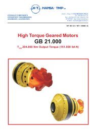
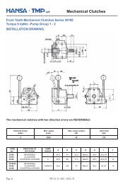
HYDRAULIC PROPORTIONAL CONTROL (<strong>without</strong> <strong>Feed</strong>-Back)<br />
With distributor direct pilot port<br />
The pump displacement is proportional to the pilot pressure on “a” or “b” piloting ports, which also affect flow<br />
direction.<br />
<strong>Feed</strong>ing pressure to the control joystick can be provided by charge pressure from "P" port.<br />
The piloting pressure must then be controlled by said joystick or by a pressure reducing valve (not supplied).<br />
IND<br />
Pilot Pressure = 4÷16 bar (on a - b)<br />
Start of control = 4 bar<br />
End of control = 16 bar (Max. displacement)<br />
Max. Pressure = 30 bar<br />
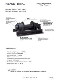
Direction of rotation<br />
Correlation between direction of rotation (shaft view) control and direction of flow.<br />
PUMP FLOW DIRECTION<br />
SHAFT<br />
ROTATION<br />
RIGHT<br />
(clockwise)<br />
LEFT<br />
(counterclockwise)<br />
Piloting<br />
Pressure<br />
a<br />
b<br />
a<br />
b<br />
Pressure<br />
Port<br />
A<br />
B<br />
B<br />
A<br />
Pag. 16 HT 16 / M / 503 / 1011 / E
Closed Loop Circuit<br />
Variable Displacement<br />
Axial Piston Pump<br />
TPV 3200<br />
HYDRAULIC PROPORTIONAL CONTROL (<strong>without</strong> <strong>Feed</strong>-Back)<br />
With distributor direct pilot port<br />
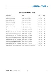
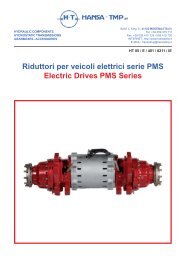
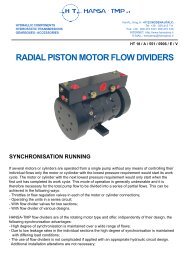
Installation Drawing<br />
IND<br />
METRIC Version<br />
A – B: Pressure Ports – 3/4" G<br />
D1 – D2: Drain Ports – 1/2" G<br />
S: Suction – 3/4 G<br />
P: Boost Presure port – ¾ "-16 UNF-2B -> ¼" G<br />
Va: Boost Pump Pressure Relief Valve<br />
V1 – V2: Main Port Pressure Relief Valve<br />
Bp: By-pass Valve<br />
Sl: Stroke Limiter<br />
Zm: Mechanical Zero adjustment screw<br />
a-b: Pilot Port - 1/8" G<br />
p: Boost Pressure Gauge Port – 1/8" G<br />
p1: a – b Pilot Line Gauge Port – 1/4" G<br />
SAE Version<br />
A – B: Pressure Ports – 7/8"-14 UNF-2B<br />
D1 – D2: Drain Ports – 3/4"-16 UNF-2B<br />
S: Suction – 1 1/16 UNF-2B<br />
P: Boost Pressure Port –3/4"-16 UNF-2B -> 7/16"-20 UNF-2B<br />
Va: Boost Pump Pressure Relief Valve<br />
V1 – V2: Main Port Pressure Relief Valve<br />
Bp: By-pass Valve<br />
Sl: Stroke Limiter<br />
Zm: Mechanical Zero adjustment screw<br />
a-b: Pilot Port - 3/8-24 UNF-2B<br />
p: Boost Pressure Gauge Port – 3/8"-24 UNF-2B<br />
p1: a – b Pilot Line Gauge Port – 7/16"-20 UNF-2B<br />
HT 16 / M / 503 / 1011 / E Pag. 17