TG, York, R-410A, ZF/ZR/XP Series, 3-5 Ton, 60 Hertz - Usair-eng.com
TG, York, R-410A, ZF/ZR/XP Series, 3-5 Ton, 60 Hertz - Usair-eng.com
TG, York, R-410A, ZF/ZR/XP Series, 3-5 Ton, 60 Hertz - Usair-eng.com

Create successful ePaper yourself
Turn your PDF publications into a flip-book with our unique Google optimized e-Paper software.
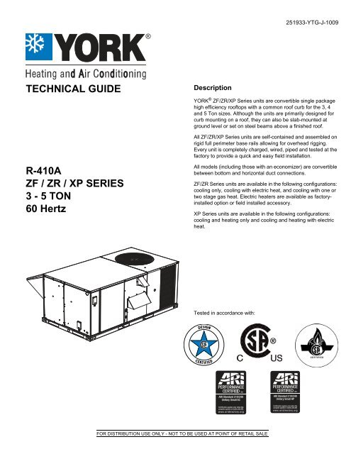
251933-Y<strong>TG</strong>-J-1009<br />
<br />
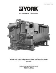
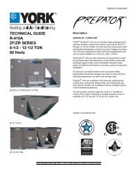
TECHNICAL GUIDE<br />
Description<br />
YORK ® <strong>ZF</strong>/<strong>ZR</strong>/<strong>XP</strong> <strong>Series</strong> units are convertible single package<br />
high efficiency rooftops with a <strong>com</strong>mon roof curb for the 3, 4<br />
and 5 <strong>Ton</strong> sizes. Although the units are primarily designed for<br />
curb mounting on a roof, they can also be slab-mounted at<br />
ground level or set on steel beams above a finished roof.<br />
All <strong>ZF</strong>/<strong>ZR</strong>/<strong>XP</strong> <strong>Series</strong> units are self-contained and assembled on<br />
rigid full perimeter base rails allowing for overhead rigging.<br />
Every unit is <strong>com</strong>pletely charged, wired, piped and tested at the<br />
factory to provide a quick and easy field installation.<br />
R-<strong>410A</strong><br />
<strong>ZF</strong> / <strong>ZR</strong> / <strong>XP</strong> SERIES<br />
3 - 5 TON<br />
<strong>60</strong> <strong>Hertz</strong><br />
All models (including those with an economizer) are convertible<br />
between bottom and horizontal duct connections.<br />
<strong>ZF</strong>/<strong>ZR</strong> <strong>Series</strong> units are available in the following configurations:<br />
cooling only, cooling with electric heat, and cooling with one or<br />
two stage gas heat. Electric heaters are available as factoryinstalled<br />
option or field installed accessory.<br />
<strong>XP</strong> <strong>Series</strong> units are available in the following configurations:<br />
cooling and heating only and cooling and heating with electric<br />
heat.<br />
Tested in accordance with:<br />
FOR DISTRIBUTION USE ONLY - NOT TO BE USED AT POINT OF RETAIL SALE
251933-Y<strong>TG</strong>-J-1009<br />
Table of Contents<br />
Description . . . . . . . . . . . . . . . . . . . . . . . . . . . . . . . . . . . . . . . . . . . . . . . . . . . . . . . . . . . . . . . . . . . . . . . . . . . . . . . . . . . . . . . . . . . . 1<br />
Table of Contents . . . . . . . . . . . . . . . . . . . . . . . . . . . . . . . . . . . . . . . . . . . . . . . . . . . . . . . . . . . . . . . . . . . . . . . . . . . . . . . . . . . . . . . 2<br />
Component Location . . . . . . . . . . . . . . . . . . . . . . . . . . . . . . . . . . . . . . . . . . . . . . . . . . . . . . . . . . . . . . . . . . . . . . . . . . . . . . . . . . . . 2<br />
Nomenclature . . . . . . . . . . . . . . . . . . . . . . . . . . . . . . . . . . . . . . . . . . . . . . . . . . . . . . . . . . . . . . . . . . . . . . . . . . . . . . . . . . . . . . . . . . 4<br />
Features and Benefits . . . . . . . . . . . . . . . . . . . . . . . . . . . . . . . . . . . . . . . . . . . . . . . . . . . . . . . . . . . . . . . . . . . . . . . . . . . . . . . . . . . . 5<br />
Guide Specifications . . . . . . . . . . . . . . . . . . . . . . . . . . . . . . . . . . . . . . . . . . . . . . . . . . . . . . . . . . . . . . . . . . . . . . . . . . . . . . . . . . . . . 8<br />
Physical Data . . . . . . . . . . . . . . . . . . . . . . . . . . . . . . . . . . . . . . . . . . . . . . . . . . . . . . . . . . . . . . . . . . . . . . . . . . . . . . . . . . . . . . . . . . 12<br />
Capacity Performance . . . . . . . . . . . . . . . . . . . . . . . . . . . . . . . . . . . . . . . . . . . . . . . . . . . . . . . . . . . . . . . . . . . . . . . . . . . . . . . . . . 19<br />
Airflow Performance . . . . . . . . . . . . . . . . . . . . . . . . . . . . . . . . . . . . . . . . . . . . . . . . . . . . . . . . . . . . . . . . . . . . . . . . . . . . . . . . . . . . 44<br />
Sound Performance . . . . . . . . . . . . . . . . . . . . . . . . . . . . . . . . . . . . . . . . . . . . . . . . . . . . . . . . . . . . . . . . . . . . . . . . . . . . . . . . . . . . 56<br />
Electrical Data . . . . . . . . . . . . . . . . . . . . . . . . . . . . . . . . . . . . . . . . . . . . . . . . . . . . . . . . . . . . . . . . . . . . . . . . . . . . . . . . . . . . . . . . . 57<br />
Typical Field Power and Control Wiring . . . . . . . . . . . . . . . . . . . . . . . . . . . . . . . . . . . . . . . . . . . . . . . . . . . . . . . . . . . . . . . . . . . . 94<br />
Weights and Dimensions . . . . . . . . . . . . . . . . . . . . . . . . . . . . . . . . . . . . . . . . . . . . . . . . . . . . . . . . . . . . . . . . . . . . . . . . . . . . . . . . 96<br />
Typical Wiring Diagrams . . . . . . . . . . . . . . . . . . . . . . . . . . . . . . . . . . . . . . . . . . . . . . . . . . . . . . . . . . . . . . . . . . . . . . . . . . . . . . . 102<br />
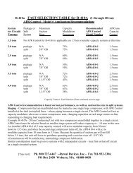
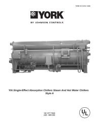
Component Location<br />
Gas/Electric<br />
Economizer<br />
hood<br />
HACR<br />
breaker<br />
Belt drive or<br />
Direct drive<br />
blower<br />
20 Gauge aluminized<br />
steel tubular heat exchanger<br />
Electric heat<br />
accessory location<br />
Power ventor motor with<br />
post purge cycle<br />
High efficiency<br />
<strong>com</strong>pressor<br />
Knockout<br />
for side<br />
power entry<br />
Slide-in<br />
economizer<br />
Highly Efficient<br />
Enhanced Copper<br />
Tube/Enhanced<br />
Aluminum Fin<br />
OR<br />
Micro-Channel<br />
Aluminum<br />
Tube/Aluminum<br />
Fin Condenser<br />
Smoke<br />
detector<br />
3/4" PVC female<br />
condensate drain<br />
Knockout for side<br />
gas supply entry<br />
Full perimeter baserails<br />
with forklift slots and<br />
lifting holes<br />
GFCI<br />
convenience outlet<br />
Simplicity® Lite<br />
control board<br />
Knockout<br />
for side<br />
control entry<br />
2 Johnson Controls Unitary Products
251933-Y<strong>TG</strong>-J-1009<br />
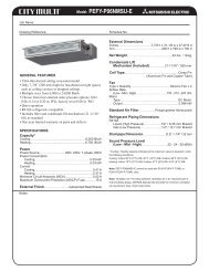
Electric/Electric and Heat Pump<br />
Economizer<br />
hood<br />
Knockout<br />
for side<br />
power entry<br />
HACR<br />
breaker<br />
Belt drive or<br />
Direct drive<br />
blower<br />
High efficiency<br />
<strong>com</strong>pressor<br />
Slide-in<br />
economizer<br />
Smoke<br />
detector<br />
Highly Efficient<br />
Enhanced Copper<br />
Tube/Enhanced<br />
Aluminum Fin<br />
OR<br />
Micro-Channel<br />
Aluminum<br />
Tube/Aluminum<br />
Fin Condenser<br />
Full perimeter baserails<br />
with forklift slots and<br />
lifting holes<br />
3/4" PVC female<br />
condensate drain<br />
Electric Heat<br />
accessory location<br />
GFCI<br />
convenience outlet<br />
Simplicity® Lite<br />
control board<br />
Knockout<br />
for side<br />
control entry<br />
Johnson Controls Unitary Products 3
251933-Y<strong>TG</strong>-J-1009<br />
Nomenclature<br />
Z F 048 N04 A 2 A AA 1 0 1 2 4 A<br />
Product Category<br />
Z = A/C, Single Pkg., R-<strong>410A</strong><br />
X = HP, Single Pkg., R-<strong>410A</strong><br />
Product Style<br />
A = Style A<br />
Product Identifier<br />
F = 13.0 SEER A/C<br />
R = 13.0 SEER Reheat<br />
P = 13.0 SEER HP<br />
Nominal Cooling Capacity<br />
036 = 3.0 <strong>Ton</strong><br />
048 = 4.0 <strong>Ton</strong><br />
0<strong>60</strong> = 5.0 <strong>Ton</strong><br />
Heat Type and Nominal Heat Capacity<br />
C00 = Cooling Only. Suitable for Field<br />
Installed Electric Heat<br />
Gas Heat Options<br />
N04 = 40 MBH Output Aluminized Steel, 1 Stage (036)<br />
N06 = <strong>60</strong> MBH Output Aluminized Steel, 1 Stage (048)<br />
N08 = 80 MBH Output Aluminized Steel, 1 Stage<br />
(036, 0<strong>60</strong>)<br />
N10 = 100 MBH Output Aluminized Steel, 1 Stage<br />
(048, 0<strong>60</strong>)<br />
D06 = <strong>60</strong> MBH Output Aluminized Steel, 2 Stage<br />
(036, 048, 0<strong>60</strong>)<br />
D10 = 100 MBH Output Aluminized Steel, 2 Stage<br />
(036*, 048, 0<strong>60</strong>)<br />
S04 = 40 MBH Output Stainless Steel, 1 Stage (036)<br />
S06 = <strong>60</strong> MBH Output Stainless Steel, 1 Stage (048)<br />
S08 = 80 MBH Output Stainless Steel, 1 Stage<br />
(036, 0<strong>60</strong>)<br />
S10 = 100 MBH Output Stainless Steel, 1 Stage<br />
(048, 0<strong>60</strong>)<br />
T06 = <strong>60</strong> MBH Output Stainless Steel, 2 Stage<br />
(036, 048, 0<strong>60</strong>)<br />
T10 = 100 MBH Output Stainless Steel, 2 Stage<br />
(036*, 048, 0<strong>60</strong>)<br />
Configuration Options (not required for all units)<br />
These four digits will not be assigned until a quote is requested, or an order placed.<br />
SS Drain Pan<br />
CPC Controller, DFS, APS<br />
Johnson Controller UNT 1126 (N2 protocol), DFS, APS<br />
Honeywell Controller, DFS, APS<br />
Novar Controller, DFS, APS<br />
Simplicity IntelliComfort Controller<br />
Simplicity IntelliComfort Controller w/ModLinc<br />
<strong>York</strong> Commercial Comfort System (YCCS) Rtu Controller<br />
2" Pleated filters<br />
BAS Ready Economizer (2-10 V.D.C. Actuator Without a Controller)<br />
Any Combination of Additional Options that Don’t Have an Option Code Pre-assigned<br />
Product Generation<br />
2 = Second Generation<br />
Standard Cabinet<br />
AA = None<br />
AB = Phase Monitor<br />
AC = Coil Guard<br />
AD = Dirty Filter Switch<br />
AE = Phase Monitor & Coil Guard<br />
AF = Phase Monitor & Dirty Filter Switch<br />
AG = Coil Guard & Dirty Filter Switch<br />
AH = Phase Monitor, Coil Guard & Dirty Filter Switch<br />
AS = Bottom Drain Connection<br />
RC = Coil Guard & American Flag<br />
TA = Technicoat Condenser Coil<br />
TJ = Technicoat Evaporator Coil<br />
TS = Technicoat Evaporator and Condenser Coil<br />
Additional Options<br />
Hinged Filter Door & Toolless Access Cabinet<br />
BA = Hinged Filter Door & Toolless Access Panels<br />
BB = Phase Monitor, Hinged Filter Door & Toolless<br />
Access Panels<br />
BC = Coil Guard, Hinged Filter Door & Toolless<br />
Access Panels<br />
BD = Dirty Filter Switch, Hinged Filter Door &<br />
Toolless Access Panels<br />
BE = Phase Monitor & Coil Guard, Hinged Filter<br />
Door & Toolless Access Panels<br />
BF = Phase Monitor & Dirty Filter Switch, Hinged<br />
Filter Door & Toolless Access Panels<br />
BG = Coil Guard & Dirty Filter Switch, Hinged Filter<br />
Door & Toolless Access Panels<br />
BH = Phase Monitor, Coil Guard & Dirty Filter Switch,<br />
Hinged Filter Door & Toolless Access Panels<br />
E05 = 5 KW<br />
E07 = 7 KW<br />
E10 = 10 KW<br />
E15 = 15 KW<br />
E20 = 20 KW<br />
E30 = 30 KW<br />
Electric Heat Options<br />
*(D, T)10 = 92 MBH Output on 036 Models<br />
Airflow<br />
A = Direct Drive<br />
B = Direct Drive/Economizer<br />
D = Direct Drive/Motorized Damper<br />
N = Belt Drive<br />
P = Belt Drive/Economizer<br />
R = Belt Drive/Motorized Damper<br />
T = Belt Drive High Static<br />
U = Belt Drive High Static/Economizer<br />
V = Belt Drive High Static/Motorized Damper<br />
Voltage<br />
1 = 208/230-1-<strong>60</strong><br />
2 = 208/230-3-<strong>60</strong><br />
4 = 4<strong>60</strong>-3-<strong>60</strong><br />
5 = 575-3-<strong>60</strong><br />
ZZ = If desired option <strong>com</strong>bination is not listed above, ZZ will be assigned and configuration options will be<br />
located in digits 15-18.<br />
Installation Options<br />
A = No Options Installed<br />
B = Option 1<br />
C = Option 2<br />
D = Options 1 & 2<br />
E = Option 3<br />
F = Option 4<br />
G = Options 1 & 3<br />
H = Options 1 & 4<br />
J = Options 1, 2 & 3<br />
K = Options 1, 2, & 4<br />
L = Options 1,3 & 4<br />
M = Options 1, 2, 3, & 4<br />
N = Options 2 & 3<br />
P = Options 2 & 4<br />
Q = Options 2, 3, & 4<br />
R = Options 3 & 4<br />
S = Option 5<br />
T = Options 1 & 5<br />
U = Options 1, 3, & 5<br />
V = Options 1, 4, & 5<br />
W = Options 1, 3, 4, & 5<br />
X = Options 3 & 5<br />
Y = Options 4 & 5<br />
Z = Options 3, 4 & 5<br />
Options<br />
1 = Disconnect<br />
2 = Non-Pwr'd Conv. Outlet<br />
3 = Smoke Detector S.A.<br />
4 = Smoke Detector R.A.<br />
5 = Pwr'd Conv. Outlet<br />
4 Johnson Controls Unitary Products
251933-Y<strong>TG</strong>-J-1009<br />
Features and Benefits<br />
Standard Features<br />
• High Efficiency - High efficiency units reach 13.0 SEER.<br />
Gas/electric units have electronic spark ignition and<br />
power vented <strong>com</strong>bustion with steady state efficiencies of<br />
80%. High efficiency heat pumps reach 13 SEER and 7.7<br />
H.S.P. F. These efficiencies exceed all legislated<br />
minimum levels and provide low operating costs.<br />
• Coil Technology – All <strong>ZF</strong> condensers utilize Micro-<br />
Channel “all-aluminum” condensers which provide<br />
improved heat transfer capabilities, superior corrosion<br />
protection and reduced charge volumes. All evaporators<br />
utilize a conventional copper tube/aluminum fin design for<br />
proven reliability and performance.<br />
• Convertible Airflow Design - All models (including those<br />
with an economizer) are suitable for either bottom or<br />
horizontal duct connections. For bottom duct, remove the<br />
sheet metal panels from the supply and return air openings<br />
through the base of the unit. For horizontal duct, remove<br />
the supply and return air panels on the rear of the unit.<br />
• System Protection - Suction line freezestats are supplied<br />
on all units to protect against loss of charge and coil<br />
frosting when the economizer operates at low outdoor air<br />
temperatures while the <strong>com</strong>pressors are running. Every<br />
unit has solid-core liquid line filter-driers and high and lowpressure<br />
switches. Internal <strong>com</strong>pressor protection is<br />
standard on all <strong>com</strong>pressors.<br />
• Advanced Controls - The Simplicity ® Lite control<br />
boards have standardized a number of features<br />
previously available only as options or by utilizing<br />
additional controls.<br />
• Low Ambient - An integrated low-ambient control<br />
allows all units to operate in the cooling mode down to<br />
0F outdoor ambient without additional assistance.<br />
Optionally, the control board can be programmed to<br />
lockout the <strong>com</strong>pressors when the outdoor air<br />
temperature is low or when free cooling is available.<br />
The Simplicity® control board used in this product<br />
will effectively operate the cooling system down to<br />
0°F when this product is applied in a <strong>com</strong>fort cooling<br />
application for people. An economizer is typically<br />
included in this type of application. When<br />
applying this product for process cooling applications<br />
(<strong>com</strong>puter rooms, switchgear, etc.), please<br />
reference applications bulletin AE-011-07 or call<br />
the applications department for Unitary Products<br />
@ 1-877-UPG-SERV for guidance. Additional<br />
accessories may be needed for stable operation at<br />
temperatures below 30° F.<br />
• Anti-Short Cycle Protection - To aid <strong>com</strong>pressor life,<br />
an anti-short cycle delay is incorporated into the<br />
standard controls. Compressor reliability is further<br />
ensured by programmable minimum run times. For<br />
testing, the anti-short cycle delay can be temporarily<br />
overridden with the push of a button.<br />
• Fan Delays - Fan on and fan off delays are fully<br />
programmable. Furthermore, the heating and cooling<br />
fan delay times are independent of one another. All units<br />
are programmed with default values based upon their<br />
configuration of cooling and heat.<br />
• Safety Monitoring - The control board monitors the<br />
high and low-pressure switches, the freezestats, the gas<br />
valve, if applicable, and the temperature limit switch on<br />
gas and electric heat units. The unit control board will<br />
alarm on ignition failures, <strong>com</strong>pressor lockouts and<br />
repeated limit switch trips.<br />
• Nuisance Trip Protection and Strikes - To prevent<br />
nuisance trouble calls, the control board uses a “three<br />
times, you’re out” philosophy. The high and lowpressure<br />
switches and the freezestats must trip three<br />
times within two hours before the unit control board will<br />
lock out the associated <strong>com</strong>pressor.<br />
• On Board Diagnostics - Each alarm will energize a<br />
trouble light on the thermostat, if so equipped, and flash<br />
an alarm code on the control board LED. Each high and<br />
low-pressure switch alarm as well as each freezestat<br />
alarm has its own flash code. The control board saves the<br />
five most recent alarms in memory, and these alarms can<br />
be reviewed at any time. Alarms and programmed values<br />
are retained through the loss of power.<br />
• Reliable - From the beginning - All units undergo<br />
<strong>com</strong>puter automated testing before they leave the factory.<br />
Units are tested for refrigerant charge and pressure, unit<br />
amperage, and 100% functionality. For the long term - All<br />
<strong>ZF</strong>/<strong>ZR</strong>/<strong>XP</strong> <strong>Series</strong> units are painted with a long lasting,<br />
powder paint that stands up over the life of the unit. The<br />
paint used has been proven by a 1000 hour salt spray<br />
test.<br />
• Flexible Placement - All models and configurations share<br />
the same cabinet/footprint and thus the same roof curb.<br />
You have the flexibility to set one curb and choose the<br />
correct tonnage size and heating option after the internal<br />
loads have been determined.<br />
• Full Perimeter Base Rails - The permanently attached<br />
base rails provide a solid foundation for the entire unit and<br />
protect the unit during shipment. The rails offer forklift<br />
access from 3 sides, and rigging holes are available so that<br />
an overhead crane can be used to place the units on a roof.<br />
• Easy Installation - Gas and electric utility knockouts are<br />
supplied in the unit underside as well as the side of the<br />
unit. A clearly identified location is provided to mount a<br />
field supplied electrical disconnect switch. Utility<br />
connections can be made quickly and with a minimum<br />
amount of field labor.<br />
• Wide Range of Indoor Airflows - Indoor fan motors are<br />
either direct-drive or belt-drive type providing maximum<br />
flexibility to handle most airflow requirements.<br />
• Gas Heat Operation - All single phase models with gas<br />
heat have minimum annual fuel utilization efficiency<br />
Johnson Controls Unitary Products 5
251933-Y<strong>TG</strong>-J-1009<br />
(AFUE) of 80%. All three phase models with gas heat<br />
have minimum steady state efficiency of 80%. Each<br />
section includes a durable heat exchanger with<br />
aluminized steel or optional stainless steel tubes, a<br />
redundant gas valve, spark ignition, power venting, an<br />
ignition module for 100% shut-off and all of the safety<br />
controls required to meet the latest ANSI standards.<br />
The gas supply piping can be routed into the heating<br />
<strong>com</strong>partment through a hole in the base pan of the unit or<br />
through a knockout in the piping panel on the front of the<br />
unit.<br />
Electric Heat Operation - All electric heat models are<br />
wired for a single power source and include a bank of<br />
nickel chromium elements mounted at the discharge of<br />
the supply air blower to provide a high velocity and<br />
uniform distribution of air across the heating elements.<br />
Every element is fully protected against excessive<br />
temperature by thermal limit switches.<br />
The power supply wiring can be routed into the control<br />
box through a threaded pipe connection (field supplied) in<br />
the base pan of the unit or through a knockout in the<br />
wiring panel on the side of the unit.<br />
• Warranty - All models include a 1-year limited warranty<br />
on the <strong>com</strong>plete unit. Compressors and electric heater<br />
elements each carry a 5-year warranty. Aluminized steel<br />
and stainless steel tubular heat exchangers carry a 10-<br />
year warranty.<br />
Factory Installed Options<br />
• Single Input Electronic Enthalpy Economizers -<br />
Includes a slide-in / plug-in damper assembly with fully<br />
modulating spring-return motor actuator capable of<br />
introducing up to 100% outdoor air with nominal 1%<br />
leakage type dampers.<br />
The enthalpy system contains one sensor that monitors<br />
the outdoor air and determines when the air is cool<br />
enough and dry enough to provide free cooling.<br />
The rain hood is painted to match the basic unit and must<br />
be field-assembled before installing.<br />
• Motorized Outdoor Air Intake Damper -Includes a slidein<br />
/ plug-in damper assembly with a 2-position, spring<br />
return motor actuator which opens to a pre-set position<br />
whenever the supply air blower is operating and will drive<br />
fully closed when the blower unit shuts down.<br />
The rain hood is painted to match the basic unit and must<br />
be field assembled before installing.<br />
• Phenolic Coated Evaporator And Condenser Coils -<br />
Special coating process that utilizes Technicoat 10-1<br />
processes. Coating is applied by total immersion of the<br />
<strong>com</strong>plete coil for maximum protection.<br />
• Electric Heaters - Wired for single point power supply.<br />
These nickel chromium heater elements are provided with<br />
limit and automatic reset capability to prevent operation at<br />
excessive temperatures.<br />
• Filter Options - Standard units are shipped with 1" throwaway<br />
filters installed. 2" pleated filters are offered as a<br />
factory installed option.<br />
• Convenience Outlet - This 110 volt outlet can be<br />
“powered” by the unit with a stepdown transformer or the<br />
unit may be ordered with a “non-powered” convenience<br />
outlet that can be wired in the field.<br />
• Disconnect Switch - For gas heat units and cooling units<br />
with electric heat, a HACR breaker sized to the unit is<br />
provided. For cooling only units, a switch sized to the<br />
largest electric heat available for the particular unit is<br />
provided. Factory installed option only.<br />
• Smoke Detectors - (supply air & return air) The smoke<br />
detectors stop operation of the unit by interrupting power<br />
to the control board if smoke is detected within the air<br />
<strong>com</strong>partment.<br />
Factory installed smoke detectors in the return air, may<br />
be subjected to freezing temperatures during “off” times<br />
due to out side air infiltration. These smoke detectors<br />
have an operational limit of 32°F to 131°F. Smoke<br />
detectors installed in areas that could be out side those<br />
limitations will have to be moved to prevent having false<br />
alarms.<br />
• Coil Guard - Customers can purchase a coil guard kit to<br />
protect the condenser coil from damage. This is not a hail<br />
guard kit.<br />
• Stainless Steel Heat Exchanger - For applications in<br />
corrosive environments, this option provides a full<br />
stainless steel heat exchanger assembly.<br />
• Stainless Steel Drain Pan - An optional rustproof<br />
stainless steel drain pan is available to provide years of<br />
trouble-free operation in corrosive environments.<br />
• Bottom Drain Connection - An optional bottom drain<br />
connection is available for inside the curb connections for<br />
applications in cold environments to reduce freezing drain<br />
lines.<br />
• Phase Monitors - Designed to prevent unit damage. The<br />
phase monitor will shut the unit down in an out-of phase<br />
condition.<br />
• Dirty Filter Switch - This kit includes a differential<br />
pressure switch that energizes the fault light on the unit<br />
thermostat, indicating that there is an abnormally high<br />
pressure drop across the filters. Factory installed option or<br />
field installed accessory.<br />
• Hinged Filter Door/”Toolless” Blower And Access<br />
Panels (Not Hinged) - This option allows for easy access<br />
and maintenance.<br />
NOTE: Knobs are shipped inside the unit to prevent shipping<br />
damage. These must be field installed for tool-less<br />
operation.<br />
• High Static Drive - May include a belt, blower pulley,<br />
motor pulley or a motor change to enhance blower<br />
performance.<br />
6 Johnson Controls Unitary Products
251933-Y<strong>TG</strong>-J-1009<br />
Control Options<br />
• BAS - Building Automation System Controls Simplicity ®<br />
INTELLI-Comfort Control - The <strong>York</strong>® Simplicity ®<br />
INTELLI-Comfort control is factory installed. It includes a<br />
supply air sensor, a return air sensor, and an outside air<br />
sensor. There are provisions for a field installed dirty filter<br />
indicator switch, an air-proving switch, an Outside Air<br />
Humidity sensor, a Return Air Humidity sensor, an Inside<br />
IAQ sensor, and an Outside Air IAQ sensor. Construction<br />
mode operation, 365-day real time clock with 7 day<br />
programming plus holiday scheduling is built-in. Two<br />
different modes of demand ventilation are achieved through<br />
the INTELLI-Comfort using CO 2 sensors. It uses an<br />
inside CO 2 sensor to perform Demand Ventilation. It can<br />
also use an Outside CO 2 sensor to perform Differential<br />
Demand Ventilation. It uses a Patented Comfort Ventilation<br />
algorithm to provide <strong>com</strong>fortable ventilation air<br />
temperature. The patented economizer-loading algorithm<br />
will protect the equipment when harsh operating conditions<br />
exist. Humidity in the occupied space or return duct can be<br />
monitored and controlled via humidity sensors and the onboard<br />
connection for hot gas re-heat system. It uses the<br />
INTELLI-Start algorithm to maximize energy savings by<br />
recovering the building from the Unoccupied Setpoints to<br />
the Occupied Setpoints just in time for the Occupied Time<br />
Period to begin. The Simplicity ® INTELLI-Comfort<br />
balances space temperature, ventilation air temperature,<br />
CO 2 and humidity for ultimate <strong>com</strong>fort.<br />
• Simplicity ® INTELLI-Comfort with ModLINC<br />
Control - The <strong>York</strong>® Simplicity ® INTELLI-Comfort with<br />
ModLINC control is factory installed. It includes all the<br />
features of the INTELLI-Comfort control with an<br />
additional control to translate <strong>com</strong>munications from<br />
MODBUS to the BACnet MSTP protocol.<br />
• Novar® BAS Control - The Novar® building automation<br />
system controller is factory installed. Incudes supply air<br />
sensor, return air sensor, dirty filter indicator switch, and<br />
air proving switch.<br />
• Johnson Controls BAS Control - The Johnson Control<br />
YK-UNT-1126 building automation system controller is<br />
factory installed. Includes supply air sensor, return air<br />
sensor, dirty filter indicator switch, and air proving switch.<br />
• CPC BAS Control - The Computer Process Controls<br />
Model 810-30<strong>60</strong> ARTC Advanced Rooftop building<br />
automation system controller is factory installed. Includes<br />
supply air sensor, return air sensor, dirty filter indicator<br />
switch and air proving switch.<br />
• Honeywell BAS Control - The Honeywell W7750C<br />
building automation system controller is factory installed.<br />
Includes air supply sensor, return air sensor, dirty filter<br />
indicator switch, and air proving switch.<br />
• <strong>York</strong> Commercial Comfort System (YCCS) - Provides<br />
rooftop system integration for YCCS single zone and<br />
change-over bypass systems.<br />
Field Installed Accessories<br />
• Single Input Electronic Enthalpy Economizers -<br />
Includes a slide-in / plug-in damper assembly with fully<br />
modulating spring-return motor actuator capable of<br />
introducing up to 100% outdoor air with nominal 1%<br />
leakage type dampers.<br />
The enthalpy system contains one sensor that monitors<br />
the outdoor air and determines when the air is cool<br />
enough and dry enough to provide free cooling.<br />
The rain hood is painted to match the basic unit and must<br />
be field-assembled before installing.<br />
• Motorized Outdoor Air Intake Damper -Includes a slidein<br />
/ plug-in damper assembly with a 2-position, spring<br />
return motor actuator which opens to some pre-set<br />
position whenever the supply air blower is operating and<br />
will drive fully closed when the blower unit shuts down.<br />
The rain hood is painted to match the basic unit and must<br />
be field assembled before installing.<br />
• Electric Heaters - wired for single point power supply.<br />
These nickel chromium heater elements are provided with<br />
limit and automatic reset capability to prevent operation at<br />
excessive temperatures.<br />
• Roof Curbs - Eight and fourteen-inch high roof curbs<br />
provide a water-tight seal between the unit and the finished<br />
roof. These full perimeter curbs meet the requirements of<br />
the National Roofing Contractors Association (NRCA) and<br />
are shipped knocked-down for field assembly.<br />
Roof curbs are designed to fit inside the base rails of the<br />
unit and include both a wood nailing strip and duct hanger<br />
supports.<br />
• High Altitude Natural Gas - Burner orifices and pilot<br />
orifices are provided for proper furnace operation at<br />
altitudes up to 6,000 feet.<br />
• Propane - Burner orifices, pilot orifices and gas valve<br />
parts are provided to convert a natural gas furnace to<br />
propane.<br />
• High Altitude Propane - Burner orifices and pilot orifices<br />
are provided for proper furnace operation at altitudes up<br />
to 6,000 feet. This accessory supplements the basic<br />
propane conversion kit.<br />
• Low Nox Kit - Required to reduce the emission of<br />
nitrogen oxides below 40 nano grams per joule.<br />
• Power Exhaust - Our single input economizer options are<br />
available with power exhaust. Whenever the outdoor air<br />
intake dampers are opened for free cooling, the exhaust<br />
fan will be energized to prevent the conditioned space from<br />
being over-pressurized during economizer operation.<br />
The power exhaust option can only be used on bottom<br />
duct configurations.<br />
Johnson Controls Unitary Products 7
251933-Y<strong>TG</strong>-J-1009<br />
• Barometric Relief Damper - This damper accessory can<br />
be used to relieve internal building air pressure on units<br />
with an economizer without power exhaust. This<br />
accessory includes a rain hood, a bird screen and a fully<br />
assembled damper. With bottom duct connections, the<br />
damper should be mounted over the opening in the return<br />
air panel. With horizontal ductwork, the accessory should<br />
be mounted on the return air duct.<br />
• Enthalpy Accessory Control Kit - This kit contains the<br />
required <strong>com</strong>ponents to convert a single enthalpy<br />
economizer to dual enthalpy.<br />
• Burglar Bars - Mount in the supply and return openings<br />
to prevent entry into the duct work.<br />
• Flue Exhaust Extension Kit - In locations with wind or<br />
weather conditions which may interfere with proper<br />
exhausting of furnace <strong>com</strong>bustion products, this kit can be<br />
installed to prevent the flue exhaust from entering nearby<br />
fresh air intakes.<br />
• CO 2 Sensor - Senses CO 2 levels and automatically<br />
overrides the economizer when levels rise above the<br />
present limits.<br />
• Coil Guard - Customers can purchase a coil guard kit to<br />
protect the condenser coil from damage. This is not a hail<br />
guard kit.<br />
• Hail Guard - Hail Guard kit is available to prevent unit<br />
from hail damage. This is a sloped hood that fits above<br />
the coil.<br />
• Gas Piping Kit - This kit supplies all necessary fittings<br />
and shut off valve.<br />
Guide Specifications<br />
General<br />
Units shall be manufactured by Johnson Controls Unitary<br />
Products in an ISO 9001 certified facility.<br />
<strong>York</strong>'s <strong>ZF</strong>/<strong>ZR</strong>/<strong>XP</strong> units are convertible single package units.<br />
Although the units are primarily designed for curb mounting on<br />
a roof, they can also be slab-mounted at ground level or set on<br />
steel beams above a finished roof. Cooling only, cooling with<br />
gas heat and cooling with electric heat models are available<br />
with a wide variety of factory-mounted options and fieldinstalled<br />
accessories to make them suitable for almost every<br />
application. All units are self-contained and assembled on full<br />
perimeter base rails with holes in the four corners for overhead<br />
rigging. Every unit is <strong>com</strong>pletely piped, wired, charged and<br />
tested at the factory to simplify the field installation and to<br />
provide years of dependable operation. All models (including<br />
those with an economizer) are suitable for either bottom or<br />
horizontal duct connections. Models with power exhaust are<br />
suitable for bottom duct connections only. For bottom duct,<br />
remove the sheet metal panels from the supply and return air<br />
openings through the base of the unit. For horizontal duct,<br />
remove the supply and return air panels on the rear of the unit.<br />
All non-Scroll <strong>com</strong>pressors include crankcase heaters and all<br />
<strong>com</strong>pressors have internal pressure relief. Every refrigerant<br />
circuit includes a liquid line filter-drier, a discharge line high<br />
pressure switch and a suction line with a freezestat and low<br />
pressure/loss of charge switch.The unit control circuit includes<br />
a 75 VA transformer, a 24-volt circuit breaker and a relay board<br />
with a <strong>com</strong>pressor lockout circuit, a terminal strip for thermostat<br />
wiring, plus an additional set of pin connectors to simplify the<br />
interface of additional field controls. All models are CSA listed.<br />
All models include a 1-year limited warranty on the <strong>com</strong>plete<br />
unit. Compressors and electric heater elements carry a 5-year<br />
warranty. Aluminized steel and Stainless steel tubular heat<br />
exchangers carry a 10-year warranty.<br />
Description<br />
Units shall be factory-assembled, single packaged, Electric<br />
Cooling/Gas Heat, Electric Cooling/Optional Electric Heat, Heat<br />
Pump/Optional Electric Heat and are designed for outdoor<br />
mounted installation.<br />
The 3 ton, 4 ton and 5 ton units shall have minimum SEER rating<br />
of 13.0 with heat pumps having a 7.7 H.S.P.F. They shall<br />
have built-in field convertible duct connections for down discharge<br />
supply/return or horizontal discharge supply/return, and<br />
be available with factory installed options or field installed<br />
accessories. The units shall be factory wired, piped, charged<br />
with R-<strong>410A</strong> refrigerant and factory tested prior to shipment. All<br />
unit wiring shall be both numbered and color coded. All units the<br />
cooling performance shall be rated in accordance with DOE<br />
and ARI test procedures. Units shall be CSA listed, classified to<br />
ANSI Z21.47, UL 1995/CSA No. 236 standards.<br />
Unit Cabinet<br />
Unit cabinet shall be constructed of galvanized steel, with<br />
exterior surfaces coated with a non-chalking, powdered paint<br />
finish, certified at 1000 hours salt spray test per ASTMB117<br />
standards. Indoor blower section shall be insulated with a<br />
minimum 1/2” thick insulation, coated on the airside. Aluminum<br />
foil faced insulation shall be used in the furnace <strong>com</strong>partment<br />
and be fastened with ridged fasteners to prevent insulation from<br />
entering the air stream. Cabinet panels shall be “large” size,<br />
easily removable for servicing and maintenance. Full perimeter<br />
base rails shall be provided to assure reliable transit of<br />
equipment, overhead rigging and proper sealing on roof curb<br />
applications. Disposable 1" filters shall be furnished and be<br />
accessible through a removable access door, sealed airtight.<br />
Units filter track shall be designed to ac<strong>com</strong>modate either 1" or<br />
2" filters. Fan performance measuring ports shall be provided<br />
on the outside of the cabinet to allow accurate air<br />
measurements of evaporator fan performance without removing<br />
panels or creating air by-pass of the coils. Condensate pan<br />
shall be internally sloped and conform to ASHRAE 62-89 selfdraining<br />
standards. Condensate connection shall be a minimum<br />
of 3/4” I.D. female and be a ridged mount connection.<br />
Indoor (Evaporator) Fan Assembly<br />
The indoor fan shall be a factory installed direct-drive or beltdrive<br />
assembly that includes an adjustable pitch motor pulley.<br />
Job site selected (B.H.P.) brake horsepower shall not exceed<br />
the motors nameplate horsepower rating, plus the service<br />
8 Johnson Controls Unitary Products
251933-Y<strong>TG</strong>-J-1009<br />
factor. Units shall be designed not to operate above service<br />
factor. Fan wheel shall be double-inlet type with forward-curved<br />
blades, dynamically balanced to operate smoothly throughout<br />
the entire range of operation. Airflow design shall be constant<br />
air volume. Bearings shall be sealed and permanently<br />
lubricated for longer life and no maintenance.<br />
Outdoor (Condenser) Fan Assembly<br />
The outdoor fan shall be of the direct-driven propeller type,<br />
discharge air vertically, have aluminum blades riveted to a<br />
corrosion resistant steel spider bracket and shall be<br />
dynamically balanced for smooth operation. The outdoor fan<br />
motor shall be totally enclosed with permanently lubricated<br />
bearings, internally protected against overload conditions and<br />
staged independently.<br />
Refrigerant Components<br />
Compressor:<br />
a. Shall be internally protected with internal high-pressure<br />
relief and over temperature protection.<br />
b. Shall have internal spring isolation and sound muffling to<br />
minimize vibration and noise, and be externally isolated<br />
on a dedicated, independent mounting.<br />
Coils:<br />
a. Evaporator coils shall have aluminum plate fins<br />
mechanically bonded to seamless internally enhanced<br />
copper tubes with all joints brazed. Special Phenolic<br />
coating shall be available as a factory option.<br />
b. Evaporator coils shall be of the direct expansion, drawthru<br />
design.<br />
c. Condenser coils shall have aluminum plate fins<br />
mechanically bonded to seamless internally enhanced<br />
copper tubes with all joints brazed or Micro-Channel<br />
aluminum tube, aluminum fins.<br />
d. Condenser coils shall be of the direct expansion, drawthru<br />
design.<br />
Refrigerant Circuit and Refrigerant Safety Components shall<br />
include:<br />
a. Independent fixed-orifice or thermally operated<br />
expansion devices.<br />
b. Filter drier/strainer to eliminate any moisture or foreign<br />
matter.<br />
c. Accessible service gage connections on both suction<br />
and liquid lines to charge, evacuate, and measure<br />
refrigerant pressure during any necessary servicing or<br />
troubleshooting, without losing charge.<br />
d. The refrigeration system shall provide at least 15°F of<br />
sub-cooling at design conditions.<br />
Unit Controls<br />
a. Unit shall be <strong>com</strong>plete with self-contained low-voltage<br />
control circuit protected by a resettable circuit breaker on<br />
the 24-volt transformer side.<br />
b. Unit shall incorporate a lockout circuit which provides<br />
reset capability at the space thermostat or base unit,<br />
should any of the following standard safety devices trip<br />
and shut off <strong>com</strong>pressor.<br />
c. Loss-of-charge/Low-pressure switch.<br />
d. High-pressure switch.<br />
e. Freeze-protection thermostat, evaporator coil.<br />
f. Unit shall incorporate “AUTO RESET” <strong>com</strong>pressor over<br />
temperature, over current protection.<br />
g. Unit shall operate with conventional thermostat designs<br />
and have a low voltage terminal strip for easy hook-up.<br />
h. Unit control board shall have on-board diagnostics and<br />
fault code display.<br />
i. Standard controls shall include anti-short cycle and low<br />
voltage protection, and permit cooling operation down to<br />
0°F.<br />
j. Control board shall monitor each refrigerant safety switch<br />
independently.<br />
k. Control board shall retain last 5 fault codes in non volatile<br />
memory which will not be lost in the event of a power loss.<br />
Gas Heating Section (Single Or 2 Stage)<br />
Shall be designed with induced draft <strong>com</strong>bustion with post<br />
purge logic, energy saving direct spark ignition, and redundant<br />
main gas valve. Venter wheel shall be constructed of stainless<br />
steel for corrosion resistance. The heat exchanger shall be of<br />
the tubular type, constructed of T1-40 aluminized steel for<br />
corrosion resistance and allowing minimum mixed air entering<br />
temperature of 25°F. Burners shall be of the inshot type,<br />
constructed of aluminum coated steel and contain air mixture<br />
adjustments. All gas piping shall enter the unit cabinet at a<br />
single location through either the side or curb without any field<br />
modifications. Integrated control boards shall provide timed<br />
control of evaporator fan functioning and burner ignition.<br />
Heating section shall be provided with the following minimum<br />
protection:<br />
a. Primary and auxiliary high-temperature limit switches.<br />
b. Induced draft motor speed sensor.<br />
c. Flame roll out switch.<br />
d. Flame proving controls.<br />
e. If any of the above safety devices trip, a LED (lightemitting<br />
diode) indicator shall flash a diagnostic code that<br />
indicates which safety switch has tripped.<br />
NOTE: All 2 Stage Gas Heat, <strong>60</strong>% Capacity 1 st Stage, 40%<br />
Capacity 2 nd Stage.<br />
Johnson Controls Unitary Products 9
251933-Y<strong>TG</strong>-J-1009<br />
Electric Heating Section<br />
An electric heating section, with nickel chromium elements,<br />
shall be provided in a range of 5 thru 30 KW, offering two<br />
stages of capacity - 16 KW and above on 208/230 volt heaters<br />
and 20 KW and above on 4<strong>60</strong> and 575 volt heaters. The<br />
heating section shall have a primary limit control(s) and<br />
automatic reset to prevent the heating element system from<br />
operating at an excessive temperature. The heating section<br />
assembly shall slide out of the unit for easy maintenance and<br />
service. Units with Electric Heating shall be wired for a single<br />
point power supply with branch circuit fusing (where required).<br />
Unit Operating Characteristics<br />
Unit shall be capable of starting and running at 125°F outdoor<br />
temperature, exceeding maximum load criteria of ARI Standard<br />
210/240. The <strong>com</strong>pressor, with standard controls, shall be<br />
capable of operation down to 0°F outdoor temperature. Unit<br />
shall be provided with fan time delay to prevent cold air delivery<br />
before heat exchanger warms up (Gas heat only).<br />
Electrical Requirements<br />
All unit power wiring shall enter unit cabinet at a single factory<br />
provided location and be capable of side or bottom entry, to<br />
minimize roof penetrations and avoid unit field modifications.<br />
Separate side and bottom openings shall be provided for the<br />
control wiring.<br />
Standard Limited Warranties<br />
• Compressor 5 Years<br />
• Heat Exchanger 10 Years<br />
• Electric Heat Element 5 Years<br />
• Other Parts 1 Year<br />
Optional Outdoor Air<br />
Shall be made available by either/or:<br />
• Electronic Enthalpy Automatic Economizer - Outdoor<br />
and return air dampers that are interlocked and positioned<br />
by a fully-modulating, spring return damper actuator. The<br />
maximum leakage rate for the outdoor air intake dampers<br />
shall not exceed 2% when dampers are fully closed and<br />
operating against a pressure differential of 0.5 IWG. A unitmounted<br />
potentiometer shall be provided to adjust the<br />
outdoor and return air damper assembly to take in CFM of<br />
outdoor air to meet the minimum ventilation requirement of<br />
the conditioned space during normal operation. During<br />
economizer operation, a mixed-air temperature control<br />
shall modulate the outdoor and return air damper assembly<br />
to prevent the supply air temperature from dropping below<br />
55°F. Changeover from <strong>com</strong>pressor to economizer<br />
operation shall be provided by an integral electronic<br />
enthalpy control that feeds input into the basic module. The<br />
outdoor intake opening shall be covered with a rain hood<br />
that matches the exterior of the unit. Water eliminator/filters<br />
shall be provided. Simultaneous economizer/<strong>com</strong>pressor<br />
operation is also possible. Dampers shall fully close on<br />
power loss.<br />
• Motorized Outdoor Air Dampers - Outdoor air dampers<br />
are positioned by a 2-position, spring-return damper<br />
actuator. The maximum leakage rate for the outdoor air<br />
intake dampers shall not exceed 2% when dampers are<br />
fully closed and operating against a pressure differential<br />
of 0.5 IWG. A unit-mounted potentiometer shall be<br />
provided to adjust the outdoor damper assembly to take in<br />
the design CFM of outdoor air to meet the ventilation<br />
requirements of the conditioned space during normal<br />
operation. Whenever the indoor fan motor is energized,<br />
the dampers open up to one of two pre-selected positions<br />
- regardless of the outdoor air enthalpy. Dampers return to<br />
the fully closed position when the indoor fan motor is deenergized.<br />
Dampers shall fully close on power loss.<br />
Other Pre-<strong>eng</strong>ineered Accessories Available<br />
• Roof Curb - 14"and 8” high, full perimeter curb with wood<br />
nailer (shipped knocked-down).<br />
• Barometric Relief Damper - Contains a rain hood, air<br />
inlet screen, exhaust damper and mounting hardware.<br />
Used to relieve internal air pressure through the unit.<br />
• Propane Conversion Kit - Contains new orifices and gas<br />
valve parts to convert from natural to L.P. gas. One per<br />
unit required.<br />
• High Altitude - Natural Gas - Contains orifices required<br />
for applications between 2000 and <strong>60</strong>00 feet altitude.<br />
• High Altitude - Propane Gas - Contains orifices required<br />
for applications between 2000 and <strong>60</strong>00 feet altitude.<br />
Must be used with propane conversion kit.<br />
• Low Nox - Required to reduce the emission of nitrogen<br />
oxides below 40 nanograms per joule.<br />
• Gas Piping - Contains 1/2” pipe nipples, fittings and gas<br />
cock (including panel assess gaskets) required for bottom<br />
gas supply connection with external shut off.<br />
• Power Exhaust Option - To work in conjunction with<br />
economizers.<br />
• Electric Heaters<br />
• Economizer/motorized Damper Rain Hood - Contains<br />
all hood panels and the hardware for assembling.<br />
• Manual Outdoor Air Damper<br />
• Coil Guard Kit - Guard for cooling coil.<br />
• Hail Guard<br />
• Flue Exhaust Extension<br />
OTHER FACTORY INSTALLED OPTIONS<br />
• Power Exhaust Option - To work in conjunction with<br />
economizers.<br />
• Stainless Steel Heat Exchanger<br />
• Stainless Steel Drain Pan<br />
• Bottom Drain Connection<br />
10 Johnson Controls Unitary Products
251933-Y<strong>TG</strong>-J-1009<br />
• Technicoat Phenolic Coated Condenser And<br />
Evaporator Coil<br />
• Electronic Single Enthalpy Economizer<br />
• Dirty Filter Switch<br />
• Phase Monitor<br />
•Coil Guard<br />
• Powered GFI Convenience Outlet<br />
• Non-powered GFI Convenience Outlet<br />
• BAS Controls (Simplicity ® INTELLI-Comfort, CPC,<br />
Johnson, Honeywell, Novar, <strong>York</strong> Commercial<br />
Comfort System (YCCS))<br />
• Bas Ready Economizer (2-10 V.D.C. Actuator Without<br />
a Controller)<br />
• Hinged Filter Door Access And Toolless Access<br />
Panels<br />
• 2" Pleated Filters<br />
• Disconnect Switch<br />
• Supply Air Smoke Detector<br />
• Return Air Smoke Detector<br />
• Direct Drive Or Belt Drive Blower With High Static<br />
Drive Option<br />
• Hot Gas Reheat with Hot Gas Bypass<br />
Johnson Controls Unitary Products 11
251933-Y<strong>TG</strong>-J-1009<br />
<strong>XP</strong>036-0<strong>60</strong> Physical Data<br />
Component<br />
Models<br />
<strong>XP</strong>036 <strong>XP</strong>048 <strong>XP</strong>0<strong>60</strong><br />
Nominal <strong>Ton</strong>nage 3.0 4.0 5.0<br />
ARI COOLING PERFORMANCE<br />
Gross Capacity @ ARI A point (Btu) 36200 48500 <strong>60</strong>100<br />
ARI net capacity (Btu) 35000 46500 57500<br />
EER 11.0 10.8 10.6<br />
SEER 13.0 13.0 13.0<br />
Nominal CFM 1200 1<strong>60</strong>0 1850<br />
System power (KW) 3.25 4.26 5.42<br />
Refrigerant type R-<strong>410A</strong> R-<strong>410A</strong> R-<strong>410A</strong><br />
Refrigerant charge (lb-oz) 13-0 13-0 12-10<br />
ARI HEATING PERFORMANCE<br />
47°F capacity rating (MBH) 34800 45000 56500<br />
System power (KW) / COP 3.29 (kW) / 3.10 4.06 (kW) / 3.25 5.4 (kW) / 3.10<br />
17°F capacity rating (MBH 19000 27000 34400<br />
System power (KW) / COP 2.<strong>60</strong> (kW) / 2.15 3.86 (kW) / 2.06 4.75 (kW) / 2.10<br />
HSPF (Btu/Watts-hr) 7.70 7.70 7.70<br />
DIMENSIONS (inches)<br />
L<strong>eng</strong>th 82-1/4 82-1/4 82-1/4<br />
Width 44-7/8 44-7/8 44-7/8<br />
Height 32-5/8 32-5/8 32-5/8<br />
OPERATING WT. (lbs.) 575 585 590<br />
COMPRESSORS<br />
Type Scroll Scroll Scroll<br />
Quantity 1 1 1<br />
CONDENSER COIL DATA<br />
Face area (Sq. Ft.) 16.88 16.88 16.88<br />
Rows 2 2 2<br />
Fins per inch 18 18 18<br />
Tube diameter 3/8 3/8 3/8<br />
Circuitry Type Split-face Split-face Split-face<br />
EVAPORATOR COIL DATA<br />
Face area (Sq. Ft.) 5.06 5.06 5.06<br />
Rows 4 4 4<br />
Fins per inch 13 13 13<br />
Tube diameter 0.375 0.375 0.375<br />
Circuitry Type Split-face Split-face Split-face<br />
Refrigerant control TXV TXV TXV<br />
16 Johnson Controls Unitary Products
251933-Y<strong>TG</strong>-J-1009<br />
<strong>XP</strong>036-0<strong>60</strong> Physical Data (Continued)<br />
Component<br />
Models<br />
<strong>XP</strong>036 <strong>XP</strong>048 <strong>XP</strong>0<strong>60</strong><br />
Nominal <strong>Ton</strong>nage 3.0 4.0 5.0<br />
CONDENSER FAN DATA<br />
Quantity 1 1 1<br />
Fan diameter (Inch) 24 24 24<br />
Type Prop Prop Prop<br />
Drive type Direct Drive Direct Drive Direct Drive<br />
No. speeds 1 1 1<br />
Number of motors 1 1 1<br />
Motor HP each 1/4 1/2 1/2<br />
RPM 850 1090 1090<br />
Nominal total CFM 3275 4200 4200<br />
BELT DRIVE EVAP FAN DATA<br />
Quantity 1 1 1<br />
Fan Size (Inch) 12 x 10 12 x 10 12 x 10<br />
Type Centrifugal Centrifugal Centrifugal<br />
Motor Sheave 1VL44 1VP56 1VL44 1VP56 1VL44 1VP56<br />
Blower Sheave AK64 AK66 AK56 AK61 AK56 AK56<br />
Belt A37 A39 A36 A38 A36 A38<br />
Motor HP each 1-1/2 1-1/2 1-1/2 1-1/2 1-1/2 2<br />
RPM 1725 1725 1725<br />
Frame size 56 56 56<br />
DIRECT DRIVE EVAP FAN DATA<br />
Quantity 1 1 1<br />
Fan Size (Inch) 12 x 10 12 x 10 12 x 10<br />
Type Centrifugal Centrifugal Centrifugal<br />
Motor HP each 3/4 1 1<br />
RPM 1050 1050 1050<br />
FILTERS<br />
15” x 20” x 1” or 2” 2 2 2<br />
14” x 25” x 1” or 2” 1 1 1<br />
Johnson Controls Unitary Products 17
251933-Y<strong>TG</strong>-J-1009<br />
<strong>ZF</strong>/<strong>ZR</strong>/<strong>XP</strong>036-0<strong>60</strong> Unit Limitations<br />
Size<br />
(<strong>Ton</strong>s)<br />
<strong>ZF</strong>/<strong>ZR</strong>/<strong>XP</strong>036<br />
(3.0)<br />
<strong>ZF</strong>/<strong>ZR</strong>/<strong>XP</strong>048<br />
(4.0)<br />
<strong>ZR</strong>/<strong>XP</strong>0<strong>60</strong><br />
(5.0)<br />
<strong>ZF</strong>0<strong>60</strong><br />
(5.0)<br />
Unit Voltage<br />
Unit Limitations<br />
Applied Voltage<br />
Outdoor DB Temp<br />
Min Max Max (°F)<br />
208/230-1-<strong>60</strong> 187 252 125<br />
208/230-3-<strong>60</strong> 187 252 125<br />
4<strong>60</strong>-3-<strong>60</strong> 432 504 125<br />
575-3-<strong>60</strong> 540 630 125<br />
208/230-1-<strong>60</strong> 187 252 125<br />
208/230-3-<strong>60</strong> 187 252 125<br />
4<strong>60</strong>-3-<strong>60</strong> 432 504 125<br />
575-3-<strong>60</strong> 540 630 125<br />
208/230-1-<strong>60</strong> 187 252 125<br />
208/230-3-<strong>60</strong> 187 252 125<br />
4<strong>60</strong>-3-<strong>60</strong> 432 504 125<br />
575-3-<strong>60</strong> 540 630 125<br />
208/230-1-<strong>60</strong> 187 252 125<br />
208/230-3-<strong>60</strong> 187 252 125<br />
4<strong>60</strong>-3-<strong>60</strong> 432 504 125<br />
575-3-<strong>60</strong> 540 630 125<br />
18 Johnson Controls Unitary Products
251933-Y<strong>TG</strong>-J-1009<br />
<strong>XP</strong>036-0<strong>60</strong> Cooling Capacities<br />
<strong>XP</strong>036 (3.0 <strong>Ton</strong>)<br />
Air on<br />
Evaporator Coil<br />
CFM<br />
750<br />
900<br />
1050<br />
1200<br />
1350<br />
1500<br />
750<br />
900<br />
1050<br />
1200<br />
1350<br />
1500<br />
WB<br />
(°F)<br />
Total<br />
Capacity 1<br />
(MBh)<br />
Sensible<br />
Temperature of Air on Condenser Coil<br />
Total<br />
Capacity (MBh) Total Total<br />
Sensible Capacity (MBh)<br />
(kW) 2 90 85 80 75 70 65 (MBh) (kW) 2 90 85 80 75 70 65<br />
Input<br />
Return Dry Bulb (°F)<br />
Capacity 1 Input<br />
Return Dry Bulb (°F)<br />
75°F 85°F<br />
77 43.4 2.1 20.2 17.0 13.8 - - - 41.3 2.4 18.4 15.3 12.2 - - -<br />
72 40.8 2.1 25.0 21.8 18.6 15.4 - - 38.5 2.4 23.2 20.2 17.1 14.0 - -<br />
67 38.2 2.1 29.9 26.7 23.5 20.3 17.1 - 35.6 2.4 28.1 25.0 21.9 18.9 15.8 -<br />
62 32.1 2.1 32.1 34.4 29.0 25.8 22.6 19.4 32.0 2.4 32.0 32.0 27.1 24.1 21.0 17.9<br />
77 45.5 2.1 22.4 18.7 15.0 - - - 42.9 2.4 20.6 17.0 13.3 - - -<br />
72 42.8 2.1 27.7 24.0 20.2 16.5 - - 40.0 2.4 25.9 22.3 18.6 15.0 - -<br />
67 40.0 2.1 32.9 29.2 25.5 21.7 18.0 - 37.0 2.4 31.2 27.6 24.0 20.3 16.7 -<br />
62 33.7 2.1 33.7 35.2 31.5 27.7 24.0 20.2 33.3 2.4 33.3 33.3 29.6 26.0 22.4 18.8<br />
57 31.0 2.1 31.0 31.0 29.4 25.6 21.9 18.1 31.2 2.4 31.2 31.2 28.7 25.1 21.5 17.9<br />
77 47.6 2.1 24.7 20.4 16.1 - - - 44.5 2.4 22.8 18.6 14.5 - - -<br />
72 44.7 2.1 30.4 26.1 21.8 17.5 - - 41.5 2.4 28.5 24.4 20.2 16.1 - -<br />
67 41.9 2.1 36.0 31.7 27.5 23.2 18.9 - 38.4 2.4 34.3 30.1 26.0 21.8 17.7 -<br />
62 35.3 2.1 35.3 36.0 33.9 29.6 25.3 21.1 34.5 2.4 34.5 34.5 32.1 28.0 23.8 19.7<br />
57 32.5 2.1 32.5 32.5 31.6 27.4 23.1 18.8 32.4 2.4 32.4 32.4 31.1 27.0 22.8 18.7<br />
77 49.6 2.1 27.0 22.1 17.3 - - - 46.1 2.4 25.0 20.3 15.6 - - -<br />
72 46.7 2.1 33.0 28.2 23.4 18.6 - - 43.0 2.4 31.1 26.5 21.8 17.1 - -<br />
67 43.7 2.1 39.1 34.3 29.4 24.6 19.8 - 39.8 2.4 37.3 32.7 28.0 23.3 18.6 -<br />
62 36.8 2.1 36.8 36.8 36.4 31.6 26.7 21.9 35.8 2.4 35.8 35.8 34.6 29.9 25.3 20.6<br />
57 33.9 2.1 33.9 33.9 33.9 29.1 24.3 19.5 33.5 2.4 33.5 33.5 33.5 28.9 24.2 19.5<br />
72 46.9 2.1 35.4 30.1 24.8 19.5 - - 43.3 2.4 33.4 28.3 23.2 18.0 - -<br />
67 43.9 2.1 41.6 36.6 31.3 26.0 20.7 - 40.1 2.4 38.8 34.9 29.8 24.6 19.5 -<br />
62 37.0 2.1 37.0 37.0 36.8 31.5 26.2 20.9 36.0 2.4 36.0 36.0 35.4 30.3 25.2 20.0<br />
57 34.1 2.1 34.1 34.1 34.1 28.8 23.5 18.2 33.8 2.4 33.8 33.8 33.8 28.6 23.5 18.4<br />
72 47.1 2.1 37.8 32.0 26.3 20.5 - - 43.6 2.4 35.7 30.2 24.6 19.0 - -<br />
67 44.1 2.1 44.1 38.8 33.1 27.3 21.5 - 40.3 2.4 40.3 37.1 31.6 26.0 20.4 -<br />
62 37.1 2.1 37.1 37.1 37.1 31.4 25.6 19.8 36.3 2.4 36.3 36.3 36.3 30.7 25.1 19.5<br />
57 34.2 2.1 34.2 34.2 34.2 28.4 22.7 16.9 34.0 2.4 34.0 34.0 34.0 28.4 22.8 17.2<br />
95°F 105°F<br />
77 39.2 2.8 16.5 13.6 10.7 - - - 35.6 3.1 14.8 12.4 9.5 - - -<br />
72 36.1 2.7 21.4 18.5 15.5 12.6 - - 32.9 3.1 20.2 17.2 14.3 11.4 - -<br />
67 33.0 2.7 26.3 23.3 20.4 17.5 14.5 - 30.2 3.1 25.5 22.1 19.1 16.2 13.3 -<br />
62 31.9 2.6 31.9 29.6 25.3 22.4 19.4 16.5 28.4 3.0 28.4 27.3 23.2 20.3 17.3 14.4<br />
77 40.3 2.8 18.7 15.2 11.7 - - - 36.8 3.1 17.4 13.9 10.5 - - -<br />
72 37.2 2.7 24.0 20.6 17.1 13.6 - - 34.0 3.1 22.7 19.3 15.8 12.3 - -<br />
67 34.0 2.7 29.4 25.9 22.4 19.0 15.5 - 31.2 3.1 28.1 24.6 21.1 17.7 14.2 -<br />
62 32.9 2.6 32.9 31.3 27.8 24.4 20.9 17.4 29.4 3.0 29.4 28.6 25.6 22.2 18.7 15.2<br />
57 31.4 2.6 31.4 31.4 28.1 24.6 21.1 17.6 28.7 3.1 28.7 28.7 25.7 22.3 18.8 15.4<br />
77 41.5 2.8 20.8 16.8 12.8 - - - 38.0 3.1 19.9 15.4 11.5 - - -<br />
72 38.2 2.7 26.7 22.6 18.6 14.6 - - 35.1 3.1 25.3 21.3 17.3 13.3 - -<br />
67 35.0 2.7 32.5 28.5 24.5 20.5 16.5 - 32.3 3.1 30.6 27.1 23.2 19.2 15.2 -<br />
62 33.8 2.6 33.8 33.0 30.4 26.4 22.3 18.3 30.4 3.0 30.4 30.0 28.0 24.1 20.1 16.1<br />
57 32.3 2.7 32.3 32.3 30.6 26.6 22.6 18.6 29.7 3.1 29.7 29.7 28.2 24.2 20.2 16.2<br />
77 42.6 2.8 22.9 18.4 13.9 - - - 39.3 3.1 22.5 17.0 12.4 - - -<br />
72 39.3 2.7 29.3 24.7 20.2 15.6 - - 36.3 3.1 27.8 23.3 18.8 14.3 - -<br />
67 35.9 2.7 35.6 31.1 26.5 22.0 17.4 - 33.3 3.0 33.2 29.7 25.2 20.6 16.1 -<br />
62 34.7 2.6 34.7 34.7 32.9 28.3 23.8 19.3 31.4 3.0 31.4 31.4 30.5 26.0 21.4 16.9<br />
57 33.2 2.7 33.2 33.2 33.2 28.6 24.1 19.5 30.6 3.1 30.6 30.6 30.6 26.1 21.6 17.1<br />
72 39.7 2.8 31.5 26.5 21.5 16.6 - - 36.3 3.1 30.0 25.0 20.1 15.1 - -<br />
67 36.3 2.7 36.1 33.3 28.3 23.3 18.3 - 33.4 3.1 33.3 31.2 26.9 21.9 17.0 -<br />
62 35.1 2.7 35.1 35.1 34.1 29.2 24.2 19.2 31.4 3.0 31.4 31.4 31.0 26.0 21.1 16.1<br />
57 33.5 2.7 33.5 33.5 33.5 28.5 23.5 18.5 30.7 3.1 30.7 30.7 30.7 25.7 20.7 15.8<br />
72 40.0 2.8 33.7 28.3 22.9 17.5 - - 36.4 3.1 32.2 26.8 21.4 16.0 - -<br />
67 36.6 2.7 36.6 35.4 30.0 24.6 19.2 - 33.4 3.1 33.4 32.8 28.6 23.2 17.8 -<br />
62 35.4 2.7 35.4 35.4 35.4 30.0 24.6 19.2 31.5 3.0 31.5 31.5 31.5 26.1 20.7 15.3<br />
57 33.8 2.7 33.8 33.8 33.8 28.4 23.0 17.6 30.7 3.1 30.7 30.7 30.7 25.3 19.9 14.5<br />
Johnson Controls Unitary Products 37
251933-Y<strong>TG</strong>-J-1009<br />
<strong>XP</strong>036 (3.0 <strong>Ton</strong>) (Continued)<br />
Sensible<br />
Air on<br />
Temperature of Air on Condenser Coil<br />
Evaporator Coil Total Total<br />
Capacity (MBh) Total Total<br />
Sensible Capacity (MBh)<br />
CFM<br />
WB Capacity 1 Input<br />
Return Dry Bulb (°F)<br />
Capacity 1 Input<br />
Return Dry Bulb (°F)<br />
(°F) (MBh) (kW) 2 90 85 80 75 70 65 (MBh) (kW) 2 90 85 80 75 70 65<br />
115°F 125°F<br />
77 31.9 3.5 13.1 11.2 8.3 - - - 28.3 3.8 11.3 10.0 7.1 - - -<br />
750<br />
72 29.6 3.5 18.9 16.0 13.1 10.1 - - 26.4 3.8 17.7 14.8 11.9 8.9 - -<br />
67 27.3 3.4 24.8 20.8 17.9 14.9 12.0 - 24.4 3.8 24.0 19.5 16.6 13.7 10.7 -<br />
62 25.0 3.5 25.0 25.0 21.1 18.1 15.2 12.3 21.5 3.9 21.5 21.5 19.0 16.0 13.1 10.2<br />
77 33.2 3.5 16.1 12.7 9.2 - - - 29.7 3.8 14.8 11.4 7.9 - - -<br />
72 30.8 3.4 21.4 18.0 14.5 11.1 - - 27.7 3.8 20.1 16.7 13.2 9.8 - -<br />
900 67 28.4 3.4 26.7 23.3 19.8 16.4 12.9 - 25.7 3.8 25.4 22.0 18.5 15.1 11.7 -<br />
62 26.0 3.4 26.0 26.0 23.4 20.0 16.5 13.1 22.6 3.8 22.6 22.6 21.2 17.8 14.3 10.9<br />
57 26.0 3.5 26.0 26.0 23.4 20.0 16.5 13.1 23.3 3.9 23.3 23.3 21.1 17.7 14.2 10.8<br />
77 34.6 3.4 19.1 14.1 10.1 - - - 31.1 3.8 18.3 12.7 8.8 - - -<br />
72 32.1 3.4 23.9 19.9 16.0 12.0 - - 29.0 3.8 22.5 18.6 14.6 10.7 - -<br />
1050 67 29.6 3.4 28.7 25.8 21.8 17.9 13.9 - 26.9 3.8 26.8 24.4 20.5 16.5 12.6 -<br />
62 27.0 3.4 27.0 27.0 25.7 21.8 17.8 13.8 23.6 3.8 23.6 23.6 23.4 19.5 15.5 11.6<br />
57 27.0 3.5 27.0 27.0 25.8 21.8 17.8 13.8 24.4 3.9 24.4 24.4 23.3 19.4 15.4 11.5<br />
77 35.9 3.4 22.1 15.5 11.0 - - - 32.5 3.7 21.8 14.1 9.6 - - -<br />
72 33.3 3.4 26.4 21.9 17.4 12.9 - - 30.3 3.7 24.9 20.5 16.0 11.6 - -<br />
1200 67 30.7 3.4 30.7 28.3 23.8 19.3 14.8 - 28.1 3.7 28.1 26.9 22.4 18.0 13.5 -<br />
62 28.1 3.4 28.1 28.1 28.1 23.6 19.1 14.6 24.7 3.8 24.7 24.7 24.7 21.2 16.7 12.3<br />
57 28.1 3.4 28.1 28.1 28.1 23.6 19.1 14.6 25.5 3.8 25.5 25.5 25.5 21.1 16.6 12.2<br />
72 33.0 3.4 28.5 23.6 18.6 13.7 - - 29.7 3.8 27.0 22.1 17.2 12.3 - -<br />
1350<br />
67 30.4 3.4 30.4 29.2 25.5 20.5 15.6 - 27.5 3.8 27.5 27.2 24.1 19.1 14.2 -<br />
62 27.8 3.4 27.8 27.8 27.8 22.9 17.9 13.0 24.2 3.8 24.2 24.2 24.2 19.7 14.8 9.9<br />
57 27.8 3.5 27.8 27.8 27.8 22.9 17.9 13.0 25.0 3.8 25.0 25.0 25.0 20.1 15.2 10.2<br />
72 32.7 3.4 30.7 25.3 19.9 14.5 - - 29.0 3.8 29.0 23.7 18.4 13.0 - -<br />
1500<br />
67 30.1 3.4 30.1 30.1 27.1 21.7 16.3 - 26.9 3.8 26.9 26.9 25.7 20.3 14.9 -<br />
62 27.6 3.4 27.6 27.6 27.6 22.2 16.8 11.4 23.6 3.8 23.6 23.6 23.6 18.2 12.9 7.5<br />
57 27.6 3.5 27.6 27.6 27.6 22.2 16.8 11.4 24.5 3.9 24.5 24.5 24.5 19.1 13.7 8.3<br />
1. These capacities are gross ratings. For net capacity, deduct air blower motor, MBh = 3.415 x kW. Refer to the appropriate Blower<br />
Performance Table for the kW of the supply air blower motor.<br />
2. These ratings include the condenser fan motors (total 1 kW) and the <strong>com</strong>pressor motors but not the supply air blower motor.<br />
38 Johnson Controls Unitary Products
251933-Y<strong>TG</strong>-J-1009<br />
<strong>XP</strong>048 (4.0 <strong>Ton</strong>)<br />
Air on<br />
Evaporator Coil<br />
CFM<br />
1000<br />
1200<br />
1400<br />
1<strong>60</strong>0<br />
1800<br />
2000<br />
1000<br />
1200<br />
1400<br />
1<strong>60</strong>0<br />
1800<br />
2000<br />
WB<br />
(°F)<br />
Total<br />
Capacity 1<br />
(MBh)<br />
Sensible<br />
Temperature of Air on Condenser Coil<br />
Total<br />
Capacity (MBh) Total Total<br />
Sensible Capacity (MBh)<br />
(kW) 2 90 85 80 75 70 65 (MBh) (kW) 2 90 85 80 75 70 65<br />
Input<br />
Return Dry Bulb (°F)<br />
Capacity 1 Input<br />
Return Dry Bulb (°F)<br />
75°F 85°F<br />
77 <strong>60</strong>.0 2.8 26.9 22.4 18.0 - - - 54.8 3.2 22.8 18.7 14.6 - - -<br />
72 55.2 2.8 33.0 28.6 24.2 19.8 - - 50.4 3.2 29.4 25.4 21.3 17.2 - -<br />
67 50.3 2.8 39.2 34.9 30.5 26.1 21.7 - 46.0 3.2 36.1 32.0 27.9 23.8 19.8 -<br />
62 45.1 2.8 45.1 43.9 37.8 33.4 29.0 24.6 40.8 3.2 40.8 39.6 33.4 29.3 25.2 21.1<br />
77 61.8 2.8 29.3 24.4 19.5 - - - 57.0 3.2 25.6 20.9 16.2 - - -<br />
72 56.8 2.8 35.9 31.0 26.1 21.3 - - 52.5 3.2 33.0 28.3 23.6 18.8 - -<br />
67 51.7 2.8 42.6 37.7 32.8 27.9 23.0 - 47.9 3.2 40.4 35.7 30.9 26.2 21.5 -<br />
62 46.5 2.8 46.5 45.6 40.7 35.9 31.0 26.1 42.5 3.2 42.5 41.7 37.0 32.3 27.5 22.8<br />
57 46.8 2.8 46.8 46.8 43.2 38.3 33.4 28.5 42.3 3.2 42.3 42.3 38.2 33.5 28.8 24.0<br />
77 63.6 2.8 31.6 26.4 21.0 - - - 59.3 3.2 28.5 23.1 17.8 - - -<br />
72 58.4 2.8 38.8 33.4 28.0 22.7 - - 54.6 3.2 36.6 31.2 25.9 20.5 - -<br />
67 53.2 2.8 46.0 40.5 35.1 29.7 24.4 - 49.8 3.2 44.7 39.3 34.0 28.6 23.2 -<br />
62 47.8 2.8 47.8 47.4 43.7 38.3 32.9 27.5 44.2 3.2 44.2 43.8 40.6 35.2 29.9 24.5<br />
57 48.2 2.8 48.2 48.2 46.3 41.0 35.6 30.2 44.0 3.2 44.0 44.0 41.9 36.6 31.2 25.8<br />
77 65.4 2.8 34.0 28.3 22.5 - - - 61.6 3.2 31.4 25.4 19.3 - - -<br />
72 <strong>60</strong>.0 2.8 41.7 35.8 29.9 24.1 - - 56.6 3.2 40.2 34.2 28.2 22.1 - -<br />
67 54.7 2.8 49.3 43.3 37.4 31.5 25.7 - 51.7 3.2 49.0 43.0 37.0 31.0 24.9 -<br />
62 49.2 2.8 49.2 49.2 46.6 40.8 34.9 29.0 45.9 3.2 45.9 45.9 44.2 38.2 32.2 26.1<br />
57 49.5 2.8 49.5 49.5 49.5 43.7 37.8 31.9 45.7 3.2 45.7 45.7 45.7 39.6 33.6 27.6<br />
72 61.4 2.8 45.7 39.0 32.3 25.6 - - 57.1 3.2 43.0 36.4 29.7 23.1 - -<br />
67 56.0 2.8 53.3 47.2 40.5 33.8 27.1 - 52.1 3.2 50.8 45.7 39.1 32.4 25.8 -<br />
62 50.3 2.8 50.3 50.3 49.0 42.3 35.6 28.9 46.3 3.2 46.3 46.3 45.4 38.8 32.2 25.5<br />
57 50.6 2.8 50.6 50.6 50.6 43.9 37.2 30.5 46.0 3.2 46.0 46.0 46.0 39.4 32.7 26.1<br />
72 62.8 2.8 49.8 42.3 34.7 27.2 - - 57.5 3.2 45.8 38.5 31.3 24.1 - -<br />
67 57.2 2.8 57.2 51.1 43.6 36.1 28.5 - 52.5 3.2 52.5 48.4 41.1 33.9 26.7 -<br />
62 51.4 2.8 51.4 51.4 51.4 43.9 36.4 28.8 46.6 3.2 46.6 46.6 46.6 39.4 32.1 24.9<br />
57 51.7 2.8 51.7 51.7 51.7 44.2 36.7 29.2 46.3 3.2 46.3 46.3 46.3 39.1 31.9 24.7<br />
95°F 105°F<br />
77 49.5 3.6 18.7 15.0 11.2 - - - 45.8 3.9 17.2 14.4 10.7 - - -<br />
72 45.6 3.6 25.8 22.1 18.3 14.5 - - 42.3 4.0 24.8 21.1 17.4 13.7 - -<br />
67 41.7 3.6 33.0 29.1 25.4 21.6 17.8 - 38.7 4.0 32.4 27.9 24.2 20.5 16.8 -<br />
62 36.5 3.6 36.5 35.4 29.0 25.2 21.5 17.7 34.2 4.0 34.2 33.7 27.7 24.0 20.3 16.6<br />
77 52.3 3.6 22.0 17.5 12.9 - - - 48.0 4.0 21.0 16.6 12.1 - - -<br />
72 48.2 3.6 30.1 25.6 21.0 16.4 - - 44.3 4.0 28.7 24.2 19.7 15.3 - -<br />
67 44.1 3.6 38.2 33.7 29.1 24.5 19.9 - 40.6 4.0 36.4 31.9 27.4 22.9 18.5 -<br />
62 38.6 3.6 38.6 37.8 33.3 28.7 24.1 19.5 35.9 4.0 35.9 35.5 31.4 26.9 22.4 18.0<br />
57 37.8 3.5 37.8 37.8 33.3 28.7 24.1 19.5 35.6 4.0 35.6 35.6 31.4 27.0 22.5 18.0<br />
77 55.0 3.6 25.4 19.9 14.5 - - - 50.3 4.0 24.9 18.8 13.5 - - -<br />
72 50.7 3.6 34.4 29.1 23.7 18.3 - - 46.4 4.0 32.6 27.3 22.1 16.8 - -<br />
67 46.4 3.6 43.5 38.2 32.8 27.4 22.1 - 42.5 4.0 40.4 35.9 30.6 25.4 20.1 -<br />
62 40.6 3.6 40.6 40.3 37.5 32.2 26.8 21.4 37.6 4.0 37.6 37.4 35.1 29.8 24.6 19.3<br />
57 39.8 3.5 39.8 39.8 37.5 32.2 26.8 21.4 37.2 4.0 37.2 37.2 35.1 29.9 24.6 19.3<br />
77 57.8 3.6 28.7 22.4 16.2 - - - 52.5 4.0 28.7 21.0 14.9 - - -<br />
72 53.3 3.6 38.7 32.6 26.4 20.2 - - 48.4 4.0 36.5 30.5 24.4 18.3 - -<br />
67 48.7 3.6 48.7 42.7 36.6 30.4 24.2 - 44.4 4.0 44.4 39.9 33.9 27.8 21.8 -<br />
62 42.7 3.6 42.7 42.7 41.8 35.6 29.4 23.3 39.2 4.0 39.2 39.2 38.8 32.7 26.7 20.6<br />
57 41.8 3.5 41.8 41.8 41.8 35.6 29.4 23.3 38.8 4.0 38.8 38.8 38.8 32.8 26.7 20.7<br />
72 52.7 3.6 40.3 33.7 27.1 20.6 - - 48.0 4.0 38.1 31.5 24.9 18.3 - -<br />
67 48.2 3.6 48.2 44.2 37.6 31.1 24.5 - 43.9 4.0 43.9 41.2 34.6 28.0 21.4 -<br />
62 42.2 3.6 42.2 42.2 41.8 35.2 28.7 22.1 38.8 4.0 38.8 38.8 38.6 32.0 25.4 18.8<br />
57 41.4 3.6 41.4 41.4 41.4 34.8 28.3 21.7 38.5 4.0 38.5 38.5 38.5 31.9 25.3 18.7<br />
72 52.2 3.6 41.8 34.8 27.9 21.0 - - 47.5 4.0 39.7 32.6 25.4 18.3 - -<br />
67 47.7 3.6 47.7 45.6 38.7 31.8 24.9 - 43.5 4.0 43.5 42.4 35.3 28.1 21.0 -<br />
62 41.8 3.6 41.8 41.8 41.8 34.9 27.9 21.0 38.5 4.0 38.5 38.5 38.5 31.3 24.2 17.0<br />
57 40.9 3.6 40.9 40.9 40.9 34.0 27.1 20.2 38.1 4.0 38.1 38.1 38.1 30.9 23.8 16.7<br />
Johnson Controls Unitary Products 39
251933-Y<strong>TG</strong>-J-1009<br />
<strong>XP</strong>048 (4.0 <strong>Ton</strong>) (Continued)<br />
Sensible<br />
Air on<br />
Temperature of Air on Condenser Coil<br />
Evaporator Coil Total Total<br />
Capacity (MBh) Total Total<br />
Sensible Capacity (MBh)<br />
CFM<br />
WB Capacity 1 Input<br />
Return Dry Bulb (°F)<br />
Capacity 1 Input<br />
Return Dry Bulb (°F)<br />
(°F) (MBh) (kW) 2 90 85 80 75 70 65 (MBh) (kW) 2 90 85 80 75 70 65<br />
115°F 125°F<br />
77 42.1 4.3 15.8 13.7 10.1 - - - 38.5 4.7 14.4 13.1 9.6 - - -<br />
1000<br />
72 38.9 4.3 23.8 20.2 16.6 13.0 - - 35.6 4.7 22.7 19.2 15.7 12.2 - -<br />
67 35.7 4.4 31.7 26.6 23.0 19.4 15.8 - 32.7 4.7 31.1 25.3 21.8 18.3 14.8 -<br />
62 31.9 4.3 31.9 31.9 26.4 22.8 19.2 15.6 29.6 4.7 29.6 29.6 25.1 21.6 18.0 14.5<br />
77 43.8 4.4 20.1 15.7 11.3 - - - 39.6 4.7 19.1 14.8 10.5 - - -<br />
72 40.5 4.4 27.3 22.9 18.5 14.1 - - 36.6 4.8 25.8 21.6 17.3 13.0 - -<br />
1200 67 37.1 4.4 34.5 30.1 25.7 21.3 17.0 - 33.7 4.8 32.6 28.3 24.0 19.8 15.5 -<br />
62 33.2 4.4 33.2 33.2 29.5 25.1 20.8 16.4 30.5 4.8 30.5 30.5 27.6 23.3 19.1 14.8<br />
57 33.3 4.4 33.3 33.3 29.6 25.2 20.8 16.5 31.0 4.8 31.0 31.0 27.7 23.5 19.2 14.9<br />
77 45.5 4.4 24.3 17.7 12.5 - - - 40.7 4.8 23.8 16.5 11.5 - - -<br />
72 42.0 4.4 30.8 25.6 20.5 15.3 - - 37.7 4.8 29.0 23.9 18.9 13.8 - -<br />
1400 67 38.5 4.4 37.2 33.6 28.5 23.3 18.1 - 34.6 4.9 34.1 31.3 26.3 21.2 16.2 -<br />
62 34.5 4.4 34.5 34.5 32.6 27.5 22.3 17.2 31.4 4.9 31.4 31.4 30.2 25.1 20.1 15.1<br />
57 34.6 4.4 34.6 34.6 32.7 27.6 22.4 17.3 32.0 4.8 32.0 32.0 30.3 25.3 20.2 15.2<br />
77 47.2 4.4 28.6 19.6 13.7 - - - 41.9 4.9 28.5 18.3 12.5 - - -<br />
72 43.6 4.4 34.3 28.4 22.4 16.5 - - 38.7 4.9 32.1 26.3 20.5 14.7 - -<br />
1<strong>60</strong>0 67 40.0 4.5 40.0 37.1 31.2 25.2 19.3 - 35.6 4.9 35.6 34.3 28.5 22.7 16.9 -<br />
62 35.8 4.5 35.8 35.8 35.8 29.8 23.9 18.0 32.3 4.9 32.3 32.3 32.3 26.9 21.1 15.3<br />
57 35.8 4.4 35.8 35.8 35.8 29.9 24.0 18.1 32.9 4.9 32.9 32.9 32.9 27.1 21.3 15.5<br />
72 43.2 4.4 36.0 29.3 22.7 16.0 - - 38.4 4.9 33.8 27.2 20.5 13.8 - -<br />
1800<br />
67 39.6 4.5 39.6 38.2 31.5 24.9 18.2 - 35.3 4.9 35.3 35.2 28.5 21.8 15.1 -<br />
62 35.5 4.5 35.5 35.5 35.5 28.8 22.2 15.5 32.1 4.9 32.1 32.1 32.1 25.6 18.9 12.2<br />
57 35.5 4.4 35.5 35.5 35.5 28.9 22.3 15.6 32.6 4.9 32.6 32.6 32.6 25.9 19.2 12.6<br />
72 42.8 4.4 37.7 30.3 22.9 15.6 - - 38.2 4.9 35.6 28.0 20.4 12.9 - -<br />
2000<br />
67 39.3 4.5 39.3 39.2 31.9 24.5 17.1 - 35.1 4.9 35.1 35.1 28.4 20.9 13.3 -<br />
62 35.1 4.4 35.1 35.1 35.1 27.8 20.4 13.0 31.8 4.9 31.8 31.8 31.8 24.2 16.7 9.1<br />
57 35.2 4.4 35.2 35.2 35.2 27.9 20.5 13.1 32.4 4.9 32.4 32.4 32.4 24.8 17.2 9.6<br />
1. These capacities are gross ratings. For net capacity, deduct air blower motor, MBh = 3.415 x kW. Refer to the appropriate Blower<br />
Performance Table for the kW of the supply air blower motor.<br />
2. These ratings include the condenser fan motors (total 1 kW) and the <strong>com</strong>pressor motors but not the supply air blower motor.<br />
40 Johnson Controls Unitary Products
251933-Y<strong>TG</strong>-J-1009<br />
<strong>XP</strong>0<strong>60</strong> (5.0 <strong>Ton</strong>)<br />
Air on<br />
Evaporator Coil<br />
CFM<br />
1250<br />
1500<br />
1750<br />
2000<br />
2250<br />
2500<br />
1250<br />
1500<br />
1750<br />
2000<br />
2250<br />
2500<br />
WB<br />
(°F)<br />
Total<br />
Capacity 1<br />
(MBh)<br />
Sensible<br />
Temperature of Air on Condenser Coil<br />
Total<br />
Capacity (MBh) Total Total<br />
Sensible Capacity (MBh)<br />
(kW) 2 90 85 80 75 70 65 (MBh) (kW) 2 90 85 80 75 70 65<br />
Input<br />
Return Dry Bulb (°F)<br />
Capacity 1 Input<br />
Return Dry Bulb (°F)<br />
75°F 85°F<br />
77 69.7 3.8 25.8 21.7 17.7 - - - 67.7 4.3 26.6 21.9 17.2 - - -<br />
72 64.2 3.7 34.2 30.1 26.0 22.0 - - 62.6 4.3 35.2 30.6 25.9 21.2 - -<br />
67 58.7 3.7 42.6 38.5 34.4 30.3 26.3 - 57.5 4.2 43.9 39.2 34.5 29.9 25.2 -<br />
62 52.8 3.6 52.8 47.5 41.2 37.1 33.1 29.0 52.0 4.2 52.0 49.4 42.1 37.4 32.7 28.0<br />
77 74.1 3.8 30.6 25.3 20.0 - - - 70.7 4.3 30.5 24.9 19.2 - - -<br />
72 68.3 3.8 40.1 34.8 29.5 24.2 - - 65.4 4.3 40.2 34.5 28.8 23.1 - -<br />
67 62.4 3.7 49.6 44.3 39.0 33.7 28.4 - <strong>60</strong>.1 4.2 49.9 44.2 38.5 32.8 27.1 -<br />
62 56.2 3.7 56.2 52.6 46.8 41.5 36.2 30.9 54.4 4.2 54.4 52.6 46.9 41.2 35.5 29.9<br />
57 54.6 3.7 54.6 54.6 49.3 44.0 38.7 33.4 53.5 4.2 53.5 53.5 48.1 42.4 36.7 31.0<br />
77 78.6 3.9 35.4 28.9 22.3 - - - 73.8 4.4 34.5 27.8 21.1 - - -<br />
72 72.3 3.8 46.0 39.5 33.0 26.5 - - 68.2 4.3 45.2 38.5 31.8 25.1 - -<br />
67 66.1 3.7 56.7 50.1 43.6 37.1 30.6 - 62.7 4.2 55.9 49.2 42.5 35.8 29.1 -<br />
62 59.6 3.7 59.6 57.8 52.3 45.8 39.3 32.7 56.8 4.2 56.8 55.9 51.8 45.1 38.4 31.7<br />
57 57.9 3.7 57.9 57.9 55.1 48.6 42.1 35.5 55.8 4.2 55.8 55.8 53.0 46.3 39.6 32.9<br />
77 83.0 3.9 40.2 32.4 24.7 - - - 76.9 4.4 38.5 30.8 23.1 - - -<br />
72 76.4 3.8 51.9 44.2 36.4 28.7 - - 71.1 4.3 50.2 42.5 34.8 27.1 - -<br />
67 69.9 3.7 63.7 56.0 48.2 40.5 32.7 - 65.3 4.2 61.8 54.1 46.4 38.7 31.0 -<br />
62 62.9 3.7 62.9 62.9 57.8 50.1 42.4 34.6 59.1 4.2 59.1 59.1 56.6 48.9 41.2 33.5<br />
57 61.2 3.7 61.2 61.2 <strong>60</strong>.9 53.2 45.4 37.7 58.1 4.2 58.1 58.1 58.0 50.3 42.5 34.8<br />
72 77.0 3.8 54.6 46.4 38.3 30.2 - - 71.7 4.3 52.8 44.7 36.6 28.5 - -<br />
67 70.4 3.8 67.3 58.8 50.7 42.5 34.4 - 65.9 4.3 64.1 57.0 48.9 40.8 32.7 -<br />
62 63.4 3.7 63.4 63.4 <strong>60</strong>.9 52.7 44.6 36.4 59.6 4.2 59.6 59.6 58.4 50.3 42.1 34.0<br />
57 61.7 3.7 61.7 61.7 61.5 53.4 45.2 37.1 58.6 4.2 58.6 58.6 58.5 50.4 42.3 34.2<br />
72 77.6 3.8 57.2 48.7 40.2 31.6 - - 72.3 4.3 55.5 47.0 38.5 30.0 - -<br />
67 70.9 3.8 70.9 61.7 53.1 44.6 36.0 - 66.4 4.3 66.4 59.9 51.4 42.9 34.4 -<br />
62 63.9 3.7 63.9 63.9 63.9 55.3 46.8 38.2 <strong>60</strong>.1 4.2 <strong>60</strong>.1 <strong>60</strong>.1 <strong>60</strong>.1 51.6 43.1 34.6<br />
57 62.1 3.7 62.1 62.1 62.1 53.6 45.0 36.5 59.1 4.2 59.1 59.1 59.1 50.6 42.1 33.6<br />
95°F 105°F<br />
77 65.6 4.8 27.3 22.0 16.7 - - - 61.6 5.4 25.0 20.8 15.6 - - -<br />
72 <strong>60</strong>.9 4.8 36.3 31.0 25.7 20.4 - - 56.8 5.4 34.5 29.3 24.2 19.0 - -<br />
67 56.3 4.7 45.3 40.0 34.7 29.4 24.1 - 52.0 5.3 44.1 37.9 32.7 27.6 22.4 -<br />
62 51.3 4.7 51.3 51.3 43.0 37.7 32.4 27.1 48.0 5.3 48.0 48.0 39.8 34.6 29.5 24.3<br />
77 67.3 4.8 30.5 24.4 18.3 - - - 63.1 5.4 29.1 23.1 17.1 - - -<br />
72 62.5 4.8 40.3 34.3 28.2 22.1 - - 58.2 5.4 38.5 32.5 26.6 20.6 - -<br />
67 57.7 4.7 50.2 44.1 38.0 31.9 25.8 - 53.3 5.3 47.9 41.9 36.0 30.0 24.0 -<br />
62 52.6 4.7 52.6 52.6 47.1 41.0 34.9 28.8 49.2 5.3 49.2 49.2 43.7 37.8 31.8 25.8<br />
57 52.4 4.7 52.4 52.4 46.8 40.8 34.7 28.6 49.1 5.3 49.1 49.1 43.6 37.7 31.7 25.8<br />
77 69.0 4.9 33.7 26.8 19.9 - - - 64.7 5.4 33.2 25.4 18.7 - - -<br />
72 64.1 4.8 44.4 37.5 30.6 23.7 - - 59.6 5.4 42.5 35.7 28.9 22.2 - -<br />
67 59.2 4.7 55.1 48.2 41.3 34.4 27.5 - 54.6 5.3 51.7 46.0 39.2 32.5 25.7 -<br />
62 54.0 4.7 54.0 54.0 51.2 44.3 37.4 30.6 50.4 5.3 50.4 50.4 47.7 40.9 34.1 27.4<br />
57 53.7 4.7 53.7 53.7 50.9 44.1 37.2 30.3 50.3 5.3 50.3 50.3 47.6 40.8 34.1 27.3<br />
77 70.8 4.9 36.9 29.2 21.5 - - - 66.2 5.5 37.3 27.8 20.2 - - -<br />
72 65.8 4.8 48.4 40.8 33.1 25.4 - - 61.1 5.4 46.4 38.9 31.3 23.8 - -<br />
67 <strong>60</strong>.7 4.7 <strong>60</strong>.0 52.3 44.6 37.0 29.3 - 55.9 5.3 55.5 50.0 42.4 34.9 27.3 -<br />
62 55.3 4.7 55.3 55.3 55.3 47.6 40.0 32.3 51.6 5.3 51.6 51.6 51.6 44.0 36.5 29.0<br />
57 55.1 4.7 55.1 55.1 55.0 47.3 39.7 32.0 51.5 5.3 51.5 51.5 51.5 43.9 36.4 28.9<br />
72 66.4 4.8 51.1 43.0 35.0 26.9 - - 61.7 5.4 49.6 41.5 33.4 25.3 - -<br />
67 61.3 4.7 <strong>60</strong>.9 55.2 47.2 39.1 31.0 - 56.5 5.3 56.3 52.6 45.3 37.2 29.1 -<br />
62 55.9 4.7 55.9 55.9 55.9 47.8 39.7 31.6 52.1 5.3 52.1 52.1 52.1 44.1 36.0 27.9<br />
57 55.6 4.7 55.6 55.6 55.6 47.5 39.4 31.4 52.1 5.3 52.1 52.1 52.1 44.0 35.9 27.8<br />
72 67.0 4.8 53.8 45.3 36.8 28.4 - - 62.4 5.4 52.7 44.1 35.5 26.9 - -<br />
67 61.9 4.7 61.9 58.2 49.7 41.2 32.7 - 57.1 5.3 57.1 55.3 48.1 39.5 30.9 -<br />
62 56.4 4.7 56.4 56.4 56.4 47.9 39.4 31.0 52.7 5.3 52.7 52.7 52.7 44.1 35.5 26.9<br />
57 56.1 4.7 56.1 56.1 56.1 47.7 39.2 30.7 52.6 5.3 52.6 52.6 52.6 44.0 35.4 26.8<br />
Johnson Controls Unitary Products 41
251933-Y<strong>TG</strong>-J-1009<br />
<strong>XP</strong>0<strong>60</strong> (5.0 <strong>Ton</strong>) (Continued)<br />
Sensible<br />
Air on<br />
Temperature of Air on Condenser Coil<br />
Evaporator Coil Total Total<br />
Capacity (MBh) Total Total<br />
Sensible Capacity (MBh)<br />
CFM<br />
WB Capacity 1 Input<br />
Return Dry Bulb (°F)<br />
Capacity 1 Input<br />
Return Dry Bulb (°F)<br />
(°F) (MBh) (kW) 2 90 85 80 75 70 65 (MBh) (kW) 2 90 85 80 75 70 65<br />
115°F 125°F<br />
77 57.6 6.0 22.6 19.5 14.5 - - - 53.6 6.6 20.0 18.3 13.4 - - -<br />
1250<br />
72 52.7 5.9 32.7 27.7 22.6 17.6 - - 48.5 6.5 31.0 26.0 21.1 16.2 - -<br />
67 47.7 5.9 42.9 35.8 30.8 25.7 20.7 - 43.5 6.5 41.7 33.8 28.8 23.9 19.0 -<br />
62 44.7 5.9 44.7 44.7 36.6 31.6 26.5 21.5 41.4 6.4 41.4 41.4 33.4 28.5 23.6 18.7<br />
77 59.0 6.0 27.6 21.8 16.0 - - - 54.8 6.6 26.2 20.5 14.8 - - -<br />
72 53.9 6.0 36.6 30.8 25.0 19.1 - - 49.6 6.5 34.8 29.1 23.4 17.7 - -<br />
1500 67 48.8 5.9 45.6 39.8 33.9 28.1 22.3 - 44.4 6.5 43.3 37.6 31.9 26.2 20.5 -<br />
62 45.8 5.9 45.8 45.8 40.4 34.5 28.7 22.9 42.3 6.5 42.3 42.3 37.0 31.3 25.6 19.9<br />
57 45.8 5.9 45.8 45.8 40.4 34.6 28.8 22.9 42.6 6.4 42.6 42.6 37.2 31.5 25.8 20.1<br />
77 <strong>60</strong>.3 6.0 32.7 24.1 17.5 - - - 56.0 6.6 32.4 22.7 16.2 - - -<br />
72 55.1 6.0 40.5 33.9 27.3 20.7 - - 50.6 6.6 38.6 32.1 25.6 19.1 - -<br />
1750 67 50.0 5.9 48.3 43.7 37.1 30.5 23.8 - 45.3 6.5 45.0 41.5 35.0 28.5 22.0 -<br />
62 46.8 5.9 46.8 46.8 44.1 37.5 30.9 24.2 43.2 6.5 43.2 43.2 40.5 34.1 27.6 21.1<br />
57 46.9 5.9 46.9 46.9 44.2 37.6 30.9 24.3 43.5 6.5 43.5 43.5 40.8 34.3 27.8 21.3<br />
77 61.7 6.0 37.8 26.4 18.9 - - - 57.1 6.6 38.6 24.9 17.7 - - -<br />
72 56.4 6.0 44.4 37.0 29.6 22.2 - - 51.7 6.6 42.4 35.1 27.9 20.6 - -<br />
2000 67 51.1 5.9 51.1 47.7 40.2 32.8 25.4 - 46.2 6.5 46.2 45.3 38.1 30.8 23.5 -<br />
62 47.8 5.9 47.8 47.8 47.8 40.4 33.0 25.6 44.1 6.5 44.1 44.1 44.1 36.8 29.6 22.3<br />
57 47.9 5.9 47.9 47.9 47.9 40.5 33.1 25.7 44.4 6.5 44.4 44.4 44.4 37.1 29.8 22.6<br />
72 57.1 6.0 48.1 40.0 31.9 23.8 - - 52.4 6.6 46.5 38.5 30.4 22.3 - -<br />
2250<br />
67 51.7 5.9 51.7 50.0 43.4 35.3 27.2 - 46.9 6.5 46.9 46.9 41.5 33.4 25.3 -<br />
62 48.4 5.9 48.4 48.4 48.4 40.4 32.3 24.2 44.7 6.5 44.7 44.7 44.7 36.6 28.6 20.5<br />
57 48.5 5.9 48.5 48.5 48.5 40.5 32.4 24.3 45.0 6.5 45.0 45.0 45.0 36.9 28.8 20.8<br />
72 57.7 6.0 51.7 43.0 34.2 25.5 - - 53.1 6.6 50.6 41.8 32.9 24.0 - -<br />
2500<br />
67 52.3 5.9 52.3 52.3 46.5 37.8 29.0 - 47.5 6.5 47.5 47.5 44.9 36.0 27.2 -<br />
62 49.0 5.9 49.0 49.0 49.0 40.3 31.5 22.8 45.3 6.5 45.3 45.3 45.3 36.4 27.6 18.7<br />
57 49.1 5.9 49.1 49.1 49.1 40.4 31.6 22.9 45.6 6.5 45.6 45.6 45.6 36.7 27.8 19.0<br />
1. These capacities are gross ratings. For net capacity, deduct air blower motor, MBh = 3.415 x kW. Refer to the appropriate Blower<br />
Performance Table for the kW of the supply air blower motor.<br />
2. These ratings include the condenser fan motors (total 1 kW) and the <strong>com</strong>pressor motors but not the supply air blower motor.<br />
42 Johnson Controls Unitary Products
251933-Y<strong>TG</strong>-J-1009<br />
<strong>XP</strong>036-0<strong>60</strong> Heating Capacities<br />
Size<br />
(<strong>Ton</strong>s)<br />
036<br />
(3.0)<br />
048<br />
(4.0)<br />
0<strong>60</strong><br />
(5.0)<br />
Model<br />
<strong>XP</strong><br />
<strong>XP</strong><br />
<strong>XP</strong><br />
Air Over Evaporator<br />
Capacity<br />
Coil<br />
&<br />
Outdoor Temperature (°F @ 72% RH)<br />
kW<br />
CFM DB (°F) -10 0 10 20 30 40 50 <strong>60</strong><br />
55<br />
MBH 8.8 13.0 17.3 21.5 25.7 29.9 34.1 38.3<br />
KW 1.6 1.6 1.7 1.7 1.8 1.9 1.9 2.0<br />
900 70<br />
MBH 5.5 9.8 14.0 18.2 22.4 26.6 30.8 35.0<br />
KW 1.9 2.0 2.1 2.1 2.2 2.2 2.3 2.4<br />
80<br />
MBH 5.1 9.3 13.5 17.7 21.9 26.2 30.4 34.6<br />
KW 2.2 2.2 2.3 2.4 2.4 2.5 2.6 2.6<br />
55<br />
MBH 10.3 14.5 18.7 22.9 27.1 31.3 35.5 39.8<br />
KW 1.2 1.3 1.4 1.4 1.5 1.6 1.6 1.7<br />
1200 70<br />
MBH 7.0 11.2 15.4 19.6 23.8 28.0 32.2 36.4<br />
KW 1.6 1.7 1.7 1.8 1.9 1.9 2.0 2.1<br />
80<br />
MBH 6.5 10.8 15.0 19.2 23.4 27.6 31.8 36.0<br />
KW 1.8 1.9 2.0 2.0 2.1 2.2 2.2 2.3<br />
55<br />
MBH 9.5 13.7 17.9 22.1 26.3 30.5 34.8 39.0<br />
KW 0.5 0.6 0.7 0.7 0.8 0.9 0.9 1.0<br />
1500 70<br />
MBH 6.2 10.4 14.6 18.8 23.0 27.3 31.5 35.7<br />
KW 0.9 1.0 1.0 1.1 1.2 1.2 1.3 1.4<br />
80<br />
MBH 5.8 10.0 14.2 18.4 22.6 26.8 31.0 35.2<br />
KW 1.2 1.2 1.3 1.4 1.4 1.5 1.5 1.6<br />
55<br />
MBH 11.8 17.1 22.5 27.9 33.3 38.6 44.0 49.4<br />
KW 2.7 2.7 2.8 2.8 2.9 2.9 3.0 3.0<br />
1200 70<br />
MBH 9.1 14.5 19.9 25.2 30.6 36.0 41.3 46.7<br />
KW 3.2 3.2 3.3 3.3 3.4 3.4 3.5 3.5<br />
80<br />
MBH 8.6 14.0 19.4 24.7 30.1 35.5 40.8 46.2<br />
KW 3.7 3.7 3.8 3.8 3.9 3.9 4.0 4.0<br />
55<br />
MBH 13.5 18.9 24.2 29.6 35.0 40.3 45.7 51.1<br />
KW 2.3 2.3 2.4 2.4 2.5 2.5 2.6 2.6<br />
1<strong>60</strong>0 70<br />
MBH 10.8 16.2 21.6 26.9 32.3 37.7 43.0 48.4<br />
KW 2.8 2.8 2.9 2.9 2.9 3.0 3.0 3.1<br />
80<br />
MBH 10.3 15.7 21.1 26.4 31.8 37.2 42.6 47.9<br />
KW 3.3 3.3 3.4 3.4 3.5 3.5 3.6 3.6<br />
55<br />
MBH 12.1 17.5 22.9 28.3 33.6 39.0 44.4 49.7<br />
KW 1.5 1.6 1.6 1.6 1.7 1.7 1.8 1.8<br />
2000 70<br />
MBH 9.5 14.9 20.2 25.6 31.0 36.3 41.7 47.1<br />
KW 2.0 2.0 2.1 2.1 2.2 2.2 2.3 2.3<br />
80<br />
MBH 9.0 14.4 19.7 25.1 30.5 35.8 41.2 46.6<br />
KW 2.5 2.6 2.6 2.7 2.7 2.7 2.8 2.8<br />
55<br />
MBH 18.1 24.6 31.1 37.7 44.2 50.8 57.3 63.8<br />
KW 3.5 3.6 3.7 3.9 4.0 4.1 4.2 4.4<br />
1500 70<br />
MBH 17.5 24.0 30.6 37.1 43.6 50.2 56.7 63.3<br />
KW 4.4 4.5 4.6 4.8 4.9 5.0 5.1 5.3<br />
80<br />
MBH 17.5 24.0 30.5 37.1 43.6 50.2 56.7 63.2<br />
KW 4.9 5.0 5.2 5.3 5.4 5.5 5.7 5.8<br />
55<br />
MBH 20.8 27.4 33.9 40.4 47.0 53.5 <strong>60</strong>.0 66.6<br />
KW 3.7 3.8 3.9 4.0 4.2 4.3 4.4 4.6<br />
2000 70<br />
MBH 20.2 26.8 33.3 39.9 46.4 52.9 59.5 66.0<br />
KW 4.6 4.7 4.8 4.9 5.1 5.2 5.3 5.5<br />
80<br />
MBH 20.2 26.8 33.3 39.8 46.4 52.9 59.4 66.0<br />
KW 5.1 5.2 5.3 5.5 5.6 5.7 5.9 6.0<br />
55<br />
MBH 23.1 29.6 36.2 42.7 49.2 55.8 62.3 68.9<br />
KW 3.9 4.0 4.1 4.3 4.4 4.5 4.6 4.8<br />
2500 70<br />
MBH 22.5 29.1 35.6 42.1 48.7 55.2 61.7 68.3<br />
KW 4.8 4.9 5.0 5.2 5.3 5.4 5.5 5.7<br />
80<br />
MBH 22.5 29.0 35.6 42.1 48.6 55.2 61.7 68.3<br />
KW 5.3 5.4 5.5 5.7 5.8 5.9 6.1 6.2<br />
1. These capacities do not include the supply air blower motor heat. For net capacity, add motor heat,<br />
MBh = 3.415 x kW.<br />
Johnson Controls Unitary Products 43
251933-Y<strong>TG</strong>-J-1009<br />
<strong>ZR</strong>036 - 0<strong>60</strong> (3-5 <strong>Ton</strong> Direct Drive) Bottom Duct<br />
UNIT<br />
TONNAGE<br />
MOTOR 1<br />
SPEED<br />
CFM<br />
1. Factory set on medium speed tap.<br />
2. Includes allowances for a wet evaporator coil, 1” filters, and the heat exchangers. Refer to STATIC RESISTANCES Table for<br />
resistance values.<br />
3. Bottom Duct application (230 Volts)<br />
<strong>XP</strong>036-0<strong>60</strong> Side Duct Application<br />
AVAILABLE EXTERNAL STATIC PRESSURE - IWG 2<br />
0.2 0.3 0.4 0.5 0.6 0.7 0.8 0.9 1.0<br />
WATTS<br />
CFM<br />
WATTS<br />
CFM<br />
WATTS<br />
CFM<br />
WATTS<br />
HI 1520 320 1478 335 1438 349 1401 363 1363 376 1327 390 1286 403 1248 417 1207 430<br />
MED/HI 1430 263 1384 276 1342 290 1302 303 1259 316 1215 329 1168 343 1114 358 1044 374<br />
3 3 MED 1287 208 1242 221 1199 234 1155 246 1108 258 10<strong>60</strong> 272 997 288 930 303 889 313<br />
MED/LOW 1185 171 1138 183 1091 195 1041 207 987 220 921 235 862 248 - - - -<br />
LOW 1040 130 959 134 900 145 - - - - - - - - - - - -<br />
4 3 MED 1662 408 1624 426 1577 438 1542 455 1501 472 1454 490 1400 505 1356 521 1323 536<br />
HI - - 1995 696 1957 714 1922 734 1885 749 1844 764 1795 769 1709 743 1566 685<br />
MED/HI 1846 539 1812 557 1776 571 1736 585 1704 <strong>60</strong>2 1662 619 1619 638 1566 653 1492 639<br />
MED/LOW 1566 362 1526 380 1480 391 1450 406 1411 423 1363 440 1312 455 1279 469 1235 485<br />
LOW 1287 223 1246 237 1190 247 - - - - - - - - - - - -<br />
5 3 MED 1940 637 1920 656 1907 675 1870 696 1834 715 1802 730 1759 740 1722 756 1657 748<br />
HI 2166 883 2169 931 2158 950 2134 964 2095 979 2040 971 1963 940 1881 898 1791 854<br />
MED/HI 20<strong>60</strong> 771 2042 784 2035 808 2006 826 1970 844 1934 859 1888 861 1821 843 1730 806<br />
MED/LOW 1688 413 1645 432 1611 451 1575 468 1534 479 1498 497 1461 513 - - - -<br />
LOW 1509 327 1477 339 - - - - - - - - - - - - - -<br />
<strong>XP</strong>036 (3 <strong>Ton</strong> Belt Drive) Side Duct<br />
Available External Static Pressure - IWG 1<br />
Air Flow<br />
0.2 0.4 0.6 0.8 1.0 1.2 1.4 1.6 1.8 2.0<br />
(CFM)<br />
RPM BHP RPM BHP RPM BHP RPM BHP RPM BHP RPM BHP RPM BHP RPM BHP RPM BHP RPM BHP<br />
Field Supplied Drive Standard Drive Option HIgh Static Drive Option<br />
800 678 0.37 761 0.44 840 0.52 917 0.<strong>60</strong> 991 0.69 1062 0.77 1130 0.87 1195 0.96 1259 1.06 1320 1.17<br />
1000 699 0.42 782 0.49 862 0.56 939 0.64 1012 0.73 1083 0.82 1151 0.91 1217 1.01 1280 1.11 1341 1.21<br />
1200 727 0.45 810 0.52 889 0.<strong>60</strong> 966 0.68 1040 0.76 1110 0.85 1179 0.95 1244 1.04 1308 1.14 1369 1.24<br />
1400 759 0.51 842 0.58 922 0.65 998 0.73 1072 0.82 1143 0.91 1211 1.00 1276 1.10 1340 1.20 1401 1.30<br />
1<strong>60</strong>0 795 0.<strong>60</strong> 878 0.67 958 0.74 1035 0.82 1108 0.91 1179 1.00 1247 1.09 1313 1.19 1376 1.28 1438 1.39<br />
FS 4<br />
1. Blower performance includes 1” filters. See STATIC RESISTANCE table for additional applications.<br />
2. See RPM SELECTION table to determine desired motor sheave setting and to determine the maximum continuous BHP.<br />
3. kW = BHP x 0.932.<br />
4. Field Supplied Drive.<br />
<strong>XP</strong>048 (4 <strong>Ton</strong> Belt Drive) Side Duct<br />
Available External Static Pressure - IWG 1<br />
Air Flow<br />
0.2 0.4 0.6 0.8 1.0 1.2 1.4 1.6 1.8 2.0<br />
(CFM)<br />
RPM BHP RPM BHP RPM BHP RPM BHP RPM BHP RPM BHP RPM BHP RPM BHP RPM BHP RPM BHP<br />
Field Supplied Drive Standard Drive Option HIgh Static Drive Option<br />
1000 699 0.42 782 0.49 862 0.56 939 0.64 1012 0.73 1083 0.82 1151 0.91 1217 1.01 1280 1.11 1341 1.21<br />
1200 727 0.45 810 0.52 889 0.<strong>60</strong> 966 0.68 1040 0.76 1110 0.85 1179 0.95 1244 1.04 1308 1.14 1369 1.24<br />
1400 759 0.51 842 0.58 922 0.65 998 0.73 1072 0.82 1143 0.91 1211 1.00 1276 1.10 1340 1.20 1401 1.30<br />
1<strong>60</strong>0 795 0.<strong>60</strong> 878 0.67 958 0.74 1035 0.82 1108 0.91 1179 1.00 1247 1.09 1313 1.19 1376 1.28 1438 1.39<br />
1800 836 0.72 919 0.79 999 0.87 1075 0.95 1149 1.03 1220 1.12 1288 1.22 1353 1.31 1417 1.41 1478 1.51<br />
2000 880 0.89 963 0.96 1042 1.04 1119 1.12 1193 1.20 1263 1.29 1331 1.39 1397 1.48 14<strong>60</strong> 1.58 1522 1.68<br />
CFM<br />
WATTS<br />
CFM<br />
WATTS<br />
CFM<br />
WATTS<br />
CFM<br />
WATTS<br />
CFM<br />
WATTS<br />
1. Blower performance includes 1” filters. See STATIC RESISTANCE table for additional applications.<br />
2. See RPM SELECTION table to determine desired motor sheave setting and to determine the maximum continuous BHP.<br />
3. kW = BHP x 0.932.<br />
Johnson Controls Unitary Products 49
251933-Y<strong>TG</strong>-J-1009<br />
<strong>XP</strong>0<strong>60</strong> (5 <strong>Ton</strong> Belt Drive) Side Duct<br />
Available External Static Pressure - IWG 1<br />
Air Flow<br />
0.2 0.4 0.6 0.8 1.0 1.2 1.4 1.6 1.8 2.0<br />
(CFM)<br />
RPM BHP RPM BHP RPM BHP RPM BHP RPM BHP RPM BHP RPM BHP RPM BHP RPM BHP RPM BHP<br />
Field Supplied Drive Standard Drive Option HIgh Static Drive Option<br />
1200 727 0.45 810 0.52 889 0.<strong>60</strong> 966 0.68 1040 0.76 1110 0.85 1179 0.95 1244 1.04 1308 1.14 1369 1.24<br />
1400 759 0.51 842 0.58 922 0.65 998 0.73 1072 0.82 1143 0.91 1211 1.00 1276 1.10 1340 1.20 1401 1.30<br />
1<strong>60</strong>0 795 0.<strong>60</strong> 878 0.67 958 0.74 1035 0.82 1108 0.91 1179 1.00 1247 1.09 1313 1.19 1376 1.28 1438 1.39<br />
1800 836 0.72 919 0.79 999 0.87 1075 0.95 1149 1.03 1220 1.12 1288 1.22 1353 1.31 1417 1.41 1478 1.51<br />
2000 880 0.89 963 0.96 1042 1.04 1119 1.12 1193 1.20 1263 1.29 1331 1.39 1397 1.48 14<strong>60</strong> 1.58 1522 1.68<br />
2200 926 1.10 1009 1.17 1089 1.25 1166 1.33 1239 1.41 1310 1.50 1378 1.<strong>60</strong> 1444 1.69 1507 1.79 1568 1.89<br />
2400 976 1.35 1059 1.42 1138 1.50 1215 1.58 1289 1.66 1359 1.75 1428 1.85 1493 1.94 1557 2.04 1618 2.14<br />
2<strong>60</strong>0 1028 1.64 1111 1.71 1190 1.78 1267 1.87 1340 1.95 1411 2.04 1479 2.13 1545 2.23 1<strong>60</strong>8 2.33 - -<br />
1. Blower performance includes 1” filters. See STATIC RESISTANCE table for additional applications.<br />
2. See RPM SELECTION table to determine desired motor sheave setting and to determine the maximum continuous BHP.<br />
3. kW = BHP x 0.932.<br />
<strong>XP</strong>036 - 0<strong>60</strong> (3-5 <strong>Ton</strong> Direct Drive) Side Duct<br />
UNIT<br />
TONNAGE<br />
MOTOR 1<br />
SPEED<br />
CFM<br />
1. Factory set on medium speed tap.<br />
2. Includes allowances for a wet evaporator coil and 1” filters. Refer to STATIC RESISTANCES Table for resistance values.<br />
3. Side Duct application (230 Volts)<br />
<strong>XP</strong>036-0<strong>60</strong> Bottom Duct Application<br />
AVAILABLE EXTERNAL STATIC PRESSURE - IWG 2<br />
0.2 0.3 0.4 0.5 0.6 0.7 0.8 0.9 1.0<br />
WATTS<br />
CFM<br />
WATTS<br />
CFM<br />
WATTS<br />
CFM<br />
WATTS<br />
HI 1528 320 1485 335 1445 349 1409 363 1370 376 1334 390 1292 403 1254 417 1213 430<br />
MED/HI 1437 263 1391 276 1349 290 1308 303 1265 316 1220 329 1173 343 1119 358 1048 374<br />
3 3 MED 1293 208 1248 221 1205 234 11<strong>60</strong> 246 1113 258 1065 272 1001 288 934 303 892 313<br />
MED/LOW 1191 171 1144 183 1096 195 1045 207 991 220 925 235 865 248 - - - -<br />
LOW 1044 130 963 134 903 145 833 158 - - - - - - - - - -<br />
4 3 MED 1672 408 1633 426 1586 438 1550 455 1509 472 1462 490 1408 505 1363 521 1330 536<br />
HI - - 2007 696 1968 714 1933 734 1896 749 1855 764 1806 769 1719 743 1574 685<br />
MED/HI 1857 539 1822 557 1786 571 1746 585 1713 <strong>60</strong>2 1671 619 1628 638 1574 653 1500 639<br />
MED/LOW 1574 362 1534 380 1487 391 1458 406 1418 423 1370 440 1319 455 1285 469 1241 485<br />
LOW 1293 223 1252 237 1196 247 - - - - - - - - - - - -<br />
5 3 MED 2010 637 1989 656 1975 675 1938 696 1900 715 1867 730 1822 740 1784 756 1716 748<br />
HI 2245 883 2247 931 2236 950 2211 964 2171 979 2114 971 2034 940 1948 898 1855 854<br />
MED/HI 2135 771 2116 784 2108 808 2078 826 2041 844 2004 859 1955 861 1886 843 1792 806<br />
MED/LOW 1748 413 1704 432 1669 451 1631 468 1589 479 1551 497 1513 513 1465 523 - -<br />
LOW 1562 327 1529 339 1491 356 - - - - - - - - - - - -<br />
<strong>XP</strong>036 (3 <strong>Ton</strong> Belt Drive) Bottom Duct<br />
Available External Static Pressure - IWG 1<br />
Air Flow<br />
0.2 0.4 0.6 0.8 1.0 1.2 1.4 1.6 1.8 2.0<br />
(CFM)<br />
RPM BHP RPM BHP RPM BHP RPM BHP RPM BHP RPM BHP RPM BHP RPM BHP RPM BHP RPM BHP<br />
Field Supplied Drive Standard Drive Option HIgh Static Drive Option<br />
800 661 0.39 751 0.45 838 0.53 922 0.61 1002 0.69 1079 0.78 1153 0.87 1225 0.96 1294 1.06 1361 1.16<br />
1000 685 0.43 775 0.50 862 0.57 945 0.65 1025 0.73 1103 0.82 1177 0.91 1248 1.00 1317 1.10 1384 1.20<br />
1200 714 0.46 805 0.53 892 0.<strong>60</strong> 975 0.68 1055 0.76 1132 0.85 1207 0.94 1278 1.04 1347 1.13 1414 1.23<br />
1400 749 0.52 840 0.58 927 0.66 1010 0.74 1090 0.82 1167 0.91 1242 1.00 1313 1.09 1382 1.19 1449 1.29<br />
1<strong>60</strong>0 789 0.<strong>60</strong> 880 0.67 967 0.74 1050 0.82 1130 0.91 1207 0.99 1282 1.08 1353 1.18 1422 1.27 1489 1.37<br />
Field Supplied Drive<br />
1. Blower performance includes 1” filters. See STATIC RESISTANCE table for additional applications.<br />
2. See RPM SELECTION table to determine desired motor sheave setting and to determine the maximum continuous BHP.<br />
3. kW = BHP x 0.932.<br />
CFM<br />
WATTS<br />
CFM<br />
WATTS<br />
CFM<br />
WATTS<br />
CFM<br />
WATTS<br />
CFM<br />
WATTS<br />
50 Johnson Controls Unitary Products
251933-Y<strong>TG</strong>-J-1009<br />
<strong>XP</strong>048 (4 <strong>Ton</strong> Belt Drive) Bottom Duct<br />
Available External Static Pressure - IWG 1<br />
Air Flow<br />
0.2 0.4 0.6 0.8 1.0 1.2 1.4 1.6 1.8 2.0<br />
(CFM)<br />
RPM BHP RPM BHP RPM BHP RPM BHP RPM BHP RPM BHP RPM BHP RPM BHP RPM BHP RPM BHP<br />
Field Supplied Drive Standard Drive Option HIgh Static Drive Option<br />
1000 685 0.43 775 0.50 862 0.57 945 0.65 1025 0.73 1103 0.82 1177 0.91 1248 1.00 1317 1.10 1384 1.20<br />
1200 714 0.46 805 0.53 892 0.<strong>60</strong> 975 0.68 1055 0.76 1132 0.85 1207 0.94 1278 1.04 1347 1.13 1414 1.23<br />
1400 749 0.52 840 0.58 927 0.66 1010 0.74 1090 0.82 1167 0.91 1242 1.00 1313 1.09 1382 1.19 1449 1.29<br />
1<strong>60</strong>0 789 0.<strong>60</strong> 880 0.67 967 0.74 1050 0.82 1130 0.91 1207 0.99 1282 1.08 1353 1.18 1422 1.27 1489 1.37<br />
1800 833 0.73 924 0.80 1011 0.87 1094 0.95 1174 1.03 1251 1.12 1326 1.21 1397 1.30 1466 1.40 1533 1.50<br />
2000 881 0.89 971 0.96 1058 1.03 1142 1.11 1222 1.20 1299 1.28 1373 1.37 1445 1.47 1514 1.57 1580 1.66<br />
FS 4<br />
1. Blower performance includes 1” filters. See STATIC RESISTANCE table for additional applications.<br />
2. See RPM SELECTION table to determine desired motor sheave setting and to determine the maximum continuous BHP.<br />
3. kW = BHP x 0.932.<br />
4. Field Supplied Drive.<br />
<strong>XP</strong>0<strong>60</strong> (5 <strong>Ton</strong> Belt Drive) Bottom Duct<br />
Available External Static Pressure - IWG 1<br />
Air Flow<br />
0.2 0.4 0.6 0.8 1.0 1.2 1.4 1.6 1.8 2.0<br />
(CFM)<br />
RPM BHP RPM BHP RPM BHP RPM BHP RPM BHP RPM BHP RPM BHP RPM BHP RPM BHP RPM BHP<br />
Field Supplied Drive Standard Drive Option HIgh Static Drive Option<br />
1200 714 0.46 805 0.53 892 0.<strong>60</strong> 975 0.68 1055 0.76 1132 0.85 1207 0.94 1278 1.04 1347 1.13 1414 1.23<br />
1400 749 0.52 840 0.58 927 0.66 1010 0.74 1090 0.82 1167 0.91 1242 1.00 1313 1.09 1382 1.19 1449 1.29<br />
1<strong>60</strong>0 789 0.<strong>60</strong> 880 0.67 967 0.74 1050 0.82 1130 0.91 1207 0.99 1282 1.08 1353 1.18 1422 1.27 1489 1.37<br />
1800 833 0.73 924 0.80 1011 0.87 1094 0.95 1174 1.03 1251 1.12 1326 1.21 1397 1.30 1466 1.40 1533 1.50<br />
2000 881 0.89 971 0.96 1058 1.03 1142 1.11 1222 1.20 1299 1.28 1373 1.37 1445 1.47 1514 1.57 1580 1.66<br />
2200 932 1.10 1022 1.17 1109 1.24 1193 1.32 1273 1.40 1350 1.49 1424 1.58 1496 1.67 1565 1.77 1631 1.87<br />
2400 986 1.34 1076 1.41 1163 1.48 1246 1.56 1327 1.64 1404 1.73 1478 1.82 1550 1.92 1619 2.01 1685 2.11<br />
2<strong>60</strong>0 1042 1.62 1132 1.69 1219 1.76 1303 1.84 1383 1.92 14<strong>60</strong> 2.01 1534 2.10 1<strong>60</strong>6 2.20 1675 2.29 - -<br />
Field Supplied Drive<br />
1. Blower performance includes 1” filters. See STATIC RESISTANCE table for additional applications.<br />
2. See RPM SELECTION table to determine desired motor sheave setting and to determine the maximum continuous BHP.<br />
3. kW = BHP x 0.932.<br />
<strong>XP</strong>036 - 0<strong>60</strong> (3-5 <strong>Ton</strong> Direct Drive) Bottom Duct<br />
UNIT<br />
TONNAGE<br />
MOTOR 1<br />
SPEED<br />
CFM<br />
AVAILABLE EXTERNAL STATIC PRESSURE - IWG 2<br />
0.2 0.3 0.4 0.5 0.6 0.7 0.8 0.9 1.0<br />
WATTS<br />
CFM<br />
WATTS<br />
CFM<br />
WATTS<br />
CFM<br />
1. Factory set on medium speed tap.<br />
2. Includes allowances for a wet evaporator coil and 1” filters. Refer to STATIC RESISTANCES Table for resistance values.<br />
3. Bottom Duct application (230 Volts)<br />
WATTS<br />
HI 1476 320 1435 335 1396 349 1361 363 1324 376 1289 390 1249 403 1212 417 1172 430<br />
MED/HI 1388 263 1344 276 1303 290 1264 303 1222 316 1179 329 1134 343 1082 358 1013 374<br />
3 3 MED 1250 208 1206 221 1164 234 1121 246 1076 258 1029 272 968 288 903 303 863 313<br />
MED/LOW 1151 171 1105 183 10<strong>60</strong> 195 1010 207 958 220 895 235 - - - - - -<br />
LOW 1009 130 932 134 874 145 - - - - - - - - - - - -<br />
4 3 MED 1614 408 1577 426 1532 438 1497 455 1458 472 1412 490 13<strong>60</strong> 505 1317 521 1285 536<br />
HI 1975 636 1937 696 1900 714 1866 734 1831 749 1791 764 1743 769 16<strong>60</strong> 743 1520 685<br />
MED/HI 1793 539 1759 557 1724 571 1685 585 1654 <strong>60</strong>2 1613 619 1572 638 1520 653 1449 639<br />
MED/LOW 1520 362 1481 380 1437 391 1408 406 1370 423 1324 440 1274 455 1242 469 1199 485<br />
LOW 1250 223 1210 237 1156 247 - - - - - - - - - - - -<br />
5 3 MED 1940 637 1920 656 1907 675 1870 696 1834 715 1802 730 1759 740 1722 756 1657 748<br />
HI 2166 883 2169 931 2158 950 2134 964 2095 979 2040 971 1963 940 1881 898 1791 854<br />
MED/HI 20<strong>60</strong> 771 2042 784 2035 808 2006 826 1970 844 1934 859 1888 861 1821 843 1730 806<br />
MED/LOW 1688 413 1645 432 1611 451 1575 468 1534 479 1498 497 1461 513 - - - -<br />
LOW 1509 327 1477 339 - - - - - - - - - - - - - -<br />
CFM<br />
WATTS<br />
CFM<br />
WATTS<br />
CFM<br />
WATTS<br />
CFM<br />
WATTS<br />
CFM<br />
WATTS<br />
Johnson Controls Unitary Products 51
251933-Y<strong>TG</strong>-J-1009<br />
Belt Drive RPM Selection<br />
Size<br />
(<strong>Ton</strong>s)<br />
036<br />
(3)<br />
048<br />
(4)<br />
0<strong>60</strong><br />
(5)<br />
036<br />
(3)<br />
048<br />
(4)<br />
0<strong>60</strong><br />
(5)<br />
Model<br />
<strong>ZF</strong>/<strong>ZR</strong><br />
<strong>ZF</strong>/<strong>ZR</strong><br />
<strong>ZF</strong>/<strong>ZR</strong><br />
<strong>XP</strong><br />
<strong>XP</strong><br />
<strong>XP</strong><br />
Additional Static Resistance<br />
Size<br />
(<strong>Ton</strong>s)<br />
036 (3.0)<br />
048 (4.0)<br />
0<strong>60</strong> (5.0)<br />
HP<br />
Max Motor Blower 5 Turns 4 Turns 3 Turns 2 Turns 1 Turn Fully<br />
BHP Sheave Sheave Open Open Open Open Open Closed<br />
1.5 1.73 1VL44 AK64 805 865 920 980 1035 1095<br />
1.5 1.73 1VP56 AK66 1115 1170 1225 1280 1335 1390<br />
1.5 1.73 1VL44 AK56 930 995 10<strong>60</strong> 1130 1195 12<strong>60</strong><br />
1.5 1.73 1VP56 AK61 1210 1270 1330 1390 1455 1515<br />
1.5 1.73 1VL44 AK56 930 995 10<strong>60</strong> 1130 1195 12<strong>60</strong><br />
2 2.3 1VP56 AK56 1325 1395 14<strong>60</strong> 1525 1590 16<strong>60</strong><br />
CFM Cooling Only 1<br />
Economizer 2 3 Electric Heat kW 2<br />
7 - 15 20 - 30<br />
1000 0.08 0.07 0.04 0.06<br />
1200 0.10 0.08 0.05 0.07<br />
1400 0.12 0.09 0.06 0.08<br />
1<strong>60</strong>0 0.14 0.11 0.07 0.09<br />
1800 0.16 0.13 0.08 0.11<br />
2000 0.18 0.15 0.10 0.13<br />
2200 0.20 0.17 0.12 0.15<br />
2400 0.23 0.20 0.14 0.17<br />
2<strong>60</strong>0 0.26 0.23 0.16 0.20<br />
2800 0.29 0.26 0.19 0.23<br />
3000 0.32 0.30 0.22 0.26<br />
1. Add these values to the available static resistance in the respective Blower Performance<br />
Tables (<strong>ZF</strong>, <strong>ZR</strong> Only).<br />
2. Deduct these values from the available external static pressure shown in the respective<br />
Blower Performance Tables.<br />
3. The pressure drop through the economizer is greater for 100% outdoor air than for 100%<br />
return air. If the resistance of the return air duct is less than 0.25 IWG, the unit will deliver<br />
less CFM during full economizer operation.<br />
52 Johnson Controls Unitary Products
251933-Y<strong>TG</strong>-J-1009<br />
Drive Selection<br />
1. Determine side or bottom supply air duct application.<br />
2. Determine desired airflow.<br />
3. Calculate or measure the amount of external static pressure.<br />
4. Using the operating point determined from steps 1, 2 & 3, locate this point on the appropriate supply air blower performance table. (Linear<br />
interpolation may be necessary.)<br />
5. Noting the RPM and BHP from step 4, locate the appropriate motor and/or drive on the RPM selection table.<br />
6. Review the BHP <strong>com</strong>pared to the motor options available. Select the appropriate motor and/or drive.<br />
7. Review the RPM range for the motor options available. Select the appropriate drive if multiple drives are available for the chosen motor.<br />
8. Determine turns open to obtain the desired operation point.<br />
Example<br />
1. 2200 CFM<br />
2. 1.6 iwg<br />
3. Using the supply air blower performance table below, the following data point was located: 1478 RPM & 1.82 BHP.<br />
4. Using the RPM selection table below, Size X and Model Y is found.<br />
5. 1.82 BHP exceeds the maximum continuous BHP rating of the 1.5 HP motor. The 2 HP motor is required.<br />
6. 1478 RPM is within the range of the 2 HP drive.<br />
7. Using the 2 HP motor and drive, 2.5 turns open will achieve 1478 RPM.<br />
Example Supply Air Blower Performance<br />
Air Flow<br />
(CFM)<br />
Available External Static Pressure - IWG<br />
0.2 0.4 0.6 0.8 1.0 1.2 1.4 1.6 1.8 2.0<br />
RPM BHP RPM BHP RPM BHP RPM BHP RPM BHP RPM BHP RPM BHP RPM BHP RPM BHP RPM BHP<br />
Field Supplied<br />
Standard Drive Option<br />
HIgh Static Drive Option<br />
Drive<br />
2000 907 1.00 990 1.07 1070 1.15 1146 1.23 1220 1.31 1291 1.40 1359 1.49 1425 1.58 1488 1.68 1550 1.77<br />
2200 9<strong>60</strong> 1.24 1043 1.31 1123 1.39 1199 1.47 1273 1.55 1344 1.64 1412 1.73 1478 1.82 1541 1.92 1<strong>60</strong>2 2.01<br />
2400 1015 1.51 1099 1.59 1178 1.66 1255 1.74 1329 1.83 1400 1.92 1468 2.01 1534 2.10 1597 2.19 1658 2.29<br />
2<strong>60</strong>0 1074 1.83 1157 1.90 1237 1.98 1314 2.06 1387 2.14 1458 2.23 - - - - - - - -<br />
Table X: RPM Selection<br />
Size<br />
(<strong>Ton</strong>s)<br />
X<br />
Model<br />
Y<br />
HP<br />
Max Motor Blower 5 Turns 4 Turns 3 Turns 2 Turns 1 Turn Fully<br />
BHP Sheave Sheave Open Open Open Open Open Closed<br />
1.5 1.73 1VL44 AK56 930 995 10<strong>60</strong> 1130 1195 12<strong>60</strong><br />
2 2.3 1VP56 AK56 1325 1395 14<strong>60</strong> 1525 1590 16<strong>60</strong><br />
Johnson Controls Unitary Products 53
251933-Y<strong>TG</strong>-J-1009<br />
Altitude/Temperature Correction Factors<br />
Air<br />
Altitude (Ft.)<br />
Temp. 0 1000 2000 3000 4000 5000 <strong>60</strong>00 7000 8000 9000 10000<br />
40 1.0<strong>60</strong> 1.022 0.986 0.950 0.916 0.882 0.849 0.818 0.788 0.758 0.729<br />
50 1.039 1.002 0.966 0.931 0.898 0.864 0.832 0.802 0.772 0.743 0.715<br />
<strong>60</strong> 1.019 0.982 0.948 0.913 0.880 0.848 0.816 0.787 0.757 0.729 0.701<br />
70 1.000 0.964 0.930 0.896 0.864 0.832 0.801 0.772 0.743 0.715 0.688<br />
80 0.982 0.947 0.913 0.880 0.848 0.817 0.787 0.758 0.730 0.702 0.676<br />
90 0.964 0.929 0.897 0.864 0.833 0.802 0.772 0.744 0.716 0.689 0.663<br />
100 0.946 0.912 0.880 0.848 0.817 0.787 0.758 0.730 0.703 0.676 0.651<br />
1.100<br />
1.050<br />
1.000<br />
Correction Factor<br />
0.950<br />
0.900<br />
0.850<br />
0.800<br />
0.750<br />
0.700<br />
0.650<br />
0.<strong>60</strong>0<br />
40 50 <strong>60</strong> 70 80 90 100<br />
Air Temperature (ºF)<br />
Sea Level<br />
1000 ft<br />
2000 ft<br />
3000 ft<br />
4000 ft<br />
5000 ft<br />
<strong>60</strong>00 ft<br />
7000 ft<br />
8000 ft<br />
9000 ft<br />
10000 ft<br />
54 Johnson Controls Unitary Products
251933-Y<strong>TG</strong>-J-1009<br />
Electric Heat Minimum Supply Air<br />
Size<br />
(<strong>Ton</strong>s)<br />
036<br />
(3.0)<br />
048<br />
(4.0)<br />
0<strong>60</strong><br />
(5.0)<br />
Minimum Supply Air (CFM)<br />
Voltage<br />
Heater kW<br />
5 7 10 15 20 30<br />
208/230-1-<strong>60</strong> 900 900 900 900 900 -<br />
208/230-3-<strong>60</strong> 900 900 900 900 900 -<br />
4<strong>60</strong>-3-<strong>60</strong> - 900 900 900 900 -<br />
<strong>60</strong>0-3-<strong>60</strong> - - 900 900 900 -<br />
208/230-1-<strong>60</strong> 1200 1200 1200 1200 1200 -<br />
208/230-3-<strong>60</strong> 1200 1200 1200 1200 1200 -<br />
4<strong>60</strong>-3-<strong>60</strong> - 1200 1200 1200 1200 -<br />
<strong>60</strong>0-3-<strong>60</strong> - - 1200 1200 1200 -<br />
208/230-1-<strong>60</strong> 1500 1500 1500 1500 1500 1500<br />
208/230-3-<strong>60</strong> 1500 1500 1500 1500 1500 1500<br />
4<strong>60</strong>-3-<strong>60</strong> - 1500 1500 1500 1500 1500<br />
<strong>60</strong>0-3-<strong>60</strong> - - 1500 1500 1500 1500<br />
Indoor Blower Specifications (Belt Drive)<br />
Size<br />
(<strong>Ton</strong>s)<br />
036<br />
(3.0)<br />
048<br />
(4.0)<br />
0<strong>60</strong><br />
(5.0)<br />
Motor Motor Sheave Blower Sheave<br />
HP RPM Eff. SF Frame<br />
Datum Dia.<br />
Datum Dia.<br />
Belt<br />
Bore (in.) Model<br />
Bore (in.) Model<br />
(in.)<br />
(in.)<br />
1-1/2 1725 0.8 1.15 56 2.8 - 3.8 7/8 1VL44 6.0 1 AK64 A37<br />
1-1/2 1725 0.8 1.15 56 4.0 - 5.0 7/8 1VP56 6.2 1 AK66 A39<br />
1-1/2 1725 0.8 1.15 56 2.8 - 3.8 7/8 1VL44 5.2 1 AK56 A36<br />
1-1/2 1725 0.8 1.15 56 4.0 - 5.0 7/8 1VP56 5.7 1 AK61 A38<br />
1-1/2 1725 0.8 1.15 56 2.8 - 3.8 7/8 1VL44 5.2 1 AK56 A36<br />
2 1725 0.8 1.15 56 4.0 - 5.0 7/8 1VP56 5.2 1 AK56 A38<br />
Power Exhaust Specifications<br />
Model Voltage<br />
Motor<br />
Motor<br />
CFM @<br />
Fuse Size<br />
HP RPM 1 QTY LRA FLA MCA<br />
0.1 ESP<br />
2PE04703025 208/230-1-<strong>60</strong> 1/2 1725 1 23.7 4.4 5.5 8 1350<br />
2PE04703046 4<strong>60</strong>-1-<strong>60</strong> 1/2 1725 1 4.1 1.7 2.1 5 1350<br />
1. Motors are multi-tapped and factory wired for high speed.<br />
Electric Heat Multipliers<br />
Voltage<br />
Nominal<br />
Applied<br />
kW Capacity Multipliers 1<br />
240<br />
208 0.75<br />
230 0.92<br />
480 4<strong>60</strong> 0.92<br />
<strong>60</strong>0 575 0.92<br />
1. Electric heaters are rated at nominal voltage. Use this table to determine the electric heat<br />
capacity for heaters applied at lower voltages.<br />
Johnson Controls Unitary Products 55
251933-Y<strong>TG</strong>-J-1009<br />
Sound Performance<br />
<strong>ZF</strong>/<strong>ZR</strong>/<strong>XP</strong> Indoor Sound Power Levels<br />
Size<br />
(<strong>Ton</strong>s)<br />
036<br />
(3.0)<br />
048<br />
(4.0)<br />
0<strong>60</strong><br />
(5.0)<br />
CFM<br />
ESP<br />
(IWG)<br />
Sound Power, dB (10 -12 ) Watts<br />
Blower<br />
Sound Rating 1<br />
Octave Band Centerline Frequency (Hz)<br />
RPM BHP dB (A) 63 125 250 500 1000 2000 4000 8000<br />
1200 0.2 630 0.41 63.0 82 77 59 50 43 42 40 45<br />
1<strong>60</strong>0 0.2 791 0.54 71.5 95 84 58 54 46 44 45 44<br />
2000 0.2 840 0.67 61.9 84 71 58 53 50 49 49 49<br />
1. These values have been accessed using a model of sound propagation from a point source into the hemispheric/free field. The<br />
dBA values provided are to be used for reference only. Calculation of dBA values cover matters of system design and the fan<br />
manufacture has no way of knowing the details of each system. This constitutes an exception to any specification or guarantee<br />
requiring a dBA value of sound data in any other form than sound power level ratings.<br />
<strong>ZF</strong>/<strong>ZR</strong> Outdoor Sound Power Levels<br />
Size<br />
(<strong>Ton</strong>s)<br />
036<br />
(3.0)<br />
048<br />
(4.0)<br />
0<strong>60</strong><br />
(5.0)<br />
Sound Rating 1<br />
dB (A)<br />
1. Rated in accordance with ARI 270 standard.<br />
<strong>XP</strong> Outdoor Sound Power Levels<br />
Size<br />
(<strong>Ton</strong>s)<br />
036<br />
(3.0)<br />
048<br />
(4.0)<br />
0<strong>60</strong><br />
(5.0)<br />
Octave Band Centerline Frequency (Hz)<br />
63 125 250 500 1000 2000 4000 8000<br />
81 87.5 86.0 81.0 77.0 75.0 69.5 65.5 70.5<br />
80 84.5 81.0 80.0 78.0 75.0 70.0 67.0 70.5<br />
82 86.5 87.5 81.5 77.5 75.0 71.5 68.0 70.5<br />
Sound Rating 1<br />
dB (A)<br />
1. Rated in accordance with ARI 270 standard.<br />
Octave Band Centerline Frequency (Hz)<br />
63 125 250 500 1000 2000 4000 8000<br />
76 83.5 84.5 76.5 72.0 68.0 66.0 <strong>60</strong>.0 56.0<br />
80 85.0 83.0 81.0 77.5 75.5 71.5 67.5 61.5<br />
80 86.0 84.0 81.0 77.0 75.5 71.0 66.5 <strong>60</strong>.5<br />
56 Johnson Controls Unitary Products
251933-Y<strong>TG</strong>-J-1009<br />
<strong>XP</strong>036-0<strong>60</strong> (Belt Drive)<br />
Size<br />
(<strong>Ton</strong>s)<br />
036<br />
(3.0)<br />
048<br />
(4.0)<br />
Volt<br />
Compressors<br />
(each)<br />
OD Fan<br />
Motors<br />
(each)<br />
Supply<br />
Blower<br />
Motor<br />
Pwr<br />
Conv<br />
Outlet<br />
Electric Heat Option<br />
RLA LRA MCC FLA FLA FLA Model kW Stages Amps<br />
208-1-<strong>60</strong> 16.6 88.0 26.0 1.6 7.6 0.0<br />
230-1-<strong>60</strong> 16.6 88.0 26.0 1.6 7.6 0.0<br />
208-3-<strong>60</strong> 12.8 95.0 20.0 1.6 5.2 0.0<br />
230-3-<strong>60</strong> 12.8 95.0 20.0 1.6 5.2 0.0<br />
4<strong>60</strong>-3-<strong>60</strong> 6.4 45.0 10.0 0.8 2.6 0.0<br />
575-3-<strong>60</strong> 5.4 38.0 8.5 0.6 2.0 0.0<br />
208-1-<strong>60</strong> 21.1 113.0 33.0 2.3 7.6 0.0<br />
230-1-<strong>60</strong> 21.1 113.0 33.0 2.3 7.6 0.0<br />
208-3-<strong>60</strong> 16.0 120.0 25.0 2.3 5.2 0.0<br />
230-3-<strong>60</strong> 16.0 120.0 25.0 2.3 5.2 0.0<br />
4<strong>60</strong>-3-<strong>60</strong> 8.3 <strong>60</strong>.0 13.0 1.3 2.6 0.0<br />
575-3-<strong>60</strong> 6.7 40.0 10.5 1.3 2.0 0.0<br />
MCA 1<br />
(Amps)<br />
Max<br />
Fuse 2 /<br />
Breaker 3<br />
Size<br />
(Amps)<br />
None - - - 30.0 40<br />
E05 4.0 1 19.2 54.0 <strong>60</strong><br />
E07 5.6 1 26.9 63.6 70<br />
E10 8.0 1 38.5 78.0 80<br />
E15 11.9 2 57.2 101.5 110<br />
E20 15.9 2 76.4 125.5 150<br />
None - - - 30.0 40<br />
E05 5.3 1 23.0 57.6 <strong>60</strong><br />
E07 7.5 1 32.6 69.0 70<br />
E10 10.6 1 46.1 85.2 90<br />
E15 15.9 2 69.1 112.8 125<br />
E20 21.2 2 92.2 140.4 150<br />
None - - - 22.8 30<br />
E05 4.0 1 11.1 36.7 45<br />
E07 5.6 1 15.5 42.2 50<br />
E10 8.0 1 22.2 50.6 <strong>60</strong><br />
E15 11.9 2 33.0 64.1 70<br />
E20 15.9 2 44.1 78.0 80<br />
None - - - 22.8 30<br />
E05 5.3 1 13.3 38.7 45<br />
E07 7.5 1 18.8 45.4 50<br />
E10 10.6 1 26.6 54.7 <strong>60</strong><br />
E15 15.9 2 39.9 70.6 80<br />
E20 21.2 2 53.2 86.5 90<br />
None - - - 11.4 15<br />
E07 6.8 1 8.5 21.6 25<br />
E10 10.1 1 12.7 26.6 30<br />
E15 13.6 2 17.1 31.8 35<br />
E20 19.5 2 24.5 40.7 45<br />
None - - - 9.2 15<br />
E10 10.6 1 10.6 22.0 25<br />
E15 15.9 1 16.0 28.4 30<br />
E20 21.2 2 21.3 34.7 35<br />
None - - - 36.3 45<br />
E05 4.0 1 19.2 <strong>60</strong>.3 70<br />
E07 5.6 1 26.9 69.9 80<br />
E10 8.0 1 38.5 84.4 90<br />
E15 11.9 2 57.2 107.8 110<br />
E20 15.9 2 76.4 131.8 150<br />
None - - - 36.3 45<br />
E05 5.3 1 23.0 63.9 70<br />
E07 7.5 1 32.6 75.3 80<br />
E10 10.6 1 46.1 91.5 100<br />
E15 15.9 2 69.1 119.1 125<br />
E20 21.2 2 92.2 146.7 150<br />
None - - - 27.5 35<br />
E05 4.0 1 11.1 41.4 50<br />
E07 5.6 1 15.5 46.9 50<br />
E10 8.0 1 22.2 55.3 <strong>60</strong><br />
E15 11.9 2 33.0 68.8 70<br />
E20 15.9 2 44.1 82.7 90<br />
None - - - 27.5 35<br />
E05 5.3 1 13.3 43.4 50<br />
E07 7.5 1 18.8 50.1 <strong>60</strong><br />
E10 10.6 1 26.6 59.4 <strong>60</strong><br />
E15 15.9 2 39.9 75.3 80<br />
E20 21.2 2 53.2 91.2 100<br />
None - - - 14.3 20<br />
E07 6.8 1 8.5 24.5 30<br />
E10 10.1 1 12.7 29.5 30<br />
E15 13.6 2 17.1 34.7 35<br />
E20 19.5 2 24.5 43.6 45<br />
None - - - 11.4 15<br />
E10 10.6 1 10.6 24.2 25<br />
E15 15.9 1 16.0 30.5 35<br />
E20 21.2 2 21.3 36.9 40<br />
70 Johnson Controls Unitary Products
251933-Y<strong>TG</strong>-J-1009<br />
<strong>XP</strong>036-0<strong>60</strong> (Belt Drive) (Continued)<br />
Size<br />
(<strong>Ton</strong>s)<br />
0<strong>60</strong><br />
(5.0)<br />
Volt<br />
Compressors<br />
(each)<br />
208-1-<strong>60</strong> 26.2 134.0 41.0 2.3 7.6 0.0<br />
230-1-<strong>60</strong> 26.2 134.0 41.0 2.3 7.6 0.0<br />
208-3-<strong>60</strong> 15.6 110.0 24.4 2.3 5.2 0.0<br />
230-3-<strong>60</strong> 15.6 110.0 24.4 2.3 5.2 0.0<br />
4<strong>60</strong>-3-<strong>60</strong> 7.7 52.0 12.1 1.3 2.6 0.0<br />
575-3-<strong>60</strong> 5.8 38.9 9.1 1.3 2.0 0.0<br />
1. Minimum Circuit Ampacity.<br />
2. Dual Element, Time Delay Type.<br />
3. HACR type per NEC.<br />
OD Fan<br />
Motors<br />
(each)<br />
Supply<br />
Blower<br />
Motor<br />
Pwr<br />
Conv<br />
Outlet<br />
Electric Heat Option<br />
RLA LRA MCC FLA FLA FLA Model kW Stages Amps<br />
MCA 1<br />
(Amps)<br />
Max<br />
Fuse 2 /<br />
Breaker 3<br />
Size<br />
(Amps)<br />
None - - - 42.7 <strong>60</strong><br />
E05 4.0 1 19.2 66.7 80<br />
E07 5.6 1 26.9 76.3 90<br />
E10 8.0 1 38.5 90.7 100<br />
E15 11.9 2 57.2 114.2 125<br />
E20 15.9 2 76.4 138.2 150<br />
E30 22.2 2 106.7 176.1 200<br />
None - - - 42.7 <strong>60</strong><br />
E05 5.3 1 23.0 70.3 90<br />
E07 7.5 1 32.6 81.7 100<br />
E10 10.6 1 46.1 97.9 110<br />
E15 15.9 2 69.1 125.5 150<br />
E20 21.2 2 92.2 153.1 175<br />
E30 29.6 2 128.7 196.8 200<br />
None - - - 27.0 35<br />
E05 4.0 1 11.1 40.9 50<br />
E07 5.6 1 15.5 46.4 50<br />
E10 8.0 1 22.2 54.8 <strong>60</strong><br />
E15 11.9 2 33.0 68.3 70<br />
E20 15.9 2 44.1 82.2 90<br />
E30 22.2 2 61.6 104.0 110<br />
None - - - 27.0 35<br />
E05 5.3 1 13.3 42.9 50<br />
E07 7.5 1 18.8 49.6 <strong>60</strong><br />
E10 10.6 1 26.6 58.9 <strong>60</strong><br />
E15 15.9 2 39.9 74.8 80<br />
E20 21.2 2 53.2 90.7 100<br />
E30 29.6 2 74.3 116.0 125<br />
None - - - 13.5 20<br />
E07 6.8 1 8.5 23.7 25<br />
E10 10.1 1 12.7 28.7 30<br />
E15 13.6 2 17.1 34.0 35<br />
E20 19.5 2 24.5 42.8 45<br />
E30 28.8 2 36.1 56.8 <strong>60</strong><br />
None - - - 10.3 15<br />
E10 10.6 1 10.6 23.0 25<br />
E15 15.9 1 16.0 29.4 30<br />
E20 21.2 2 21.3 35.8 40<br />
E30 30.4 2 30.5 46.9 50<br />
Johnson Controls Unitary Products 71
251933-Y<strong>TG</strong>-J-1009<br />
<strong>XP</strong>036-0<strong>60</strong> (Belt Drive High Static)<br />
Size<br />
(<strong>Ton</strong>s)<br />
036<br />
(3.0)<br />
048<br />
(4.0)<br />
Volt<br />
Compressors<br />
(each)<br />
OD Fan<br />
Motors<br />
(each)<br />
Supply<br />
Blower<br />
Motor<br />
Pwr<br />
Conv<br />
Outlet<br />
Electric Heat Option<br />
RLA LRA MCC FLA FLA FLA Model kW Stages Amps<br />
208-1-<strong>60</strong> 16.6 88.0 26.0 1.6 7.6 0.0<br />
230-1-<strong>60</strong> 16.6 88.0 26.0 1.6 7.6 0.0<br />
208-3-<strong>60</strong> 12.8 95.0 20.0 1.6 5.2 0.0<br />
230-3-<strong>60</strong> 12.8 95.0 20.0 1.6 5.2 0.0<br />
4<strong>60</strong>-3-<strong>60</strong> 6.4 45.0 10.0 0.8 2.6 0.0<br />
575-3-<strong>60</strong> 5.4 38.0 8.5 0.6 2.0 0.0<br />
208-1-<strong>60</strong> 21.1 113.0 33.0 2.3 7.6 0.0<br />
230-1-<strong>60</strong> 21.1 113.0 33.0 2.3 7.6 0.0<br />
208-3-<strong>60</strong> 16.0 120.0 25.0 2.3 5.2 0.0<br />
230-3-<strong>60</strong> 16.0 120.0 25.0 2.3 5.2 0.0<br />
4<strong>60</strong>-3-<strong>60</strong> 8.3 <strong>60</strong>.0 13.0 1.3 2.6 0.0<br />
575-3-<strong>60</strong> 6.7 40.0 10.5 1.3 2.0 0.0<br />
MCA 1<br />
(Amps)<br />
Max<br />
Fuse 2 /<br />
Breaker 3<br />
Size<br />
(Amps)<br />
None - - - 30.0 40<br />
E05 4.0 1 19.2 54.0 <strong>60</strong><br />
E07 5.6 1 26.9 63.6 70<br />
E10 8.0 1 38.5 78.0 80<br />
E15 11.9 2 57.2 101.5 110<br />
E20 15.9 2 76.4 125.5 150<br />
None - - - 30.0 40<br />
E05 5.3 1 23.0 57.6 <strong>60</strong><br />
E07 7.5 1 32.6 69.0 70<br />
E10 10.6 1 46.1 85.2 90<br />
E15 15.9 2 69.1 112.8 125<br />
E20 21.2 2 92.2 140.4 150<br />
None - - - 22.8 30<br />
E05 4.0 1 11.1 36.7 45<br />
E07 5.6 1 15.5 42.2 50<br />
E10 8.0 1 22.2 50.6 <strong>60</strong><br />
E15 11.9 2 33.0 64.1 70<br />
E20 15.9 2 44.1 78.0 80<br />
None - - - 22.8 30<br />
E05 5.3 1 13.3 38.7 45<br />
E07 7.5 1 18.8 45.4 50<br />
E10 10.6 1 26.6 54.7 <strong>60</strong><br />
E15 15.9 2 39.9 70.6 80<br />
E20 21.2 2 53.2 86.5 90<br />
None - - - 11.4 15<br />
E07 6.8 1 8.5 21.6 25<br />
E10 10.1 1 12.7 26.6 30<br />
E15 13.6 2 17.1 31.8 35<br />
E20 19.5 2 24.5 40.7 45<br />
None - - - 9.2 15<br />
E10 10.6 1 10.6 22.0 25<br />
E15 15.9 1 16.0 28.4 30<br />
E20 21.2 2 21.3 34.7 35<br />
None - - - 36.3 45<br />
E05 4.0 1 19.2 <strong>60</strong>.3 70<br />
E07 5.6 1 26.9 69.9 80<br />
E10 8.0 1 38.5 84.4 90<br />
E15 11.9 2 57.2 107.8 110<br />
E20 15.9 2 76.4 131.8 150<br />
None - - - 36.3 45<br />
E05 5.3 1 23.0 63.9 70<br />
E07 7.5 1 32.6 75.3 80<br />
E10 10.6 1 46.1 91.5 100<br />
E15 15.9 2 69.1 119.1 125<br />
E20 21.2 2 92.2 146.7 150<br />
None - - - 27.5 35<br />
E05 4.0 1 11.1 41.4 50<br />
E07 5.6 1 15.5 46.9 50<br />
E10 8.0 1 22.2 55.3 <strong>60</strong><br />
E15 11.9 2 33.0 68.8 70<br />
E20 15.9 2 44.1 82.7 90<br />
None - - - 27.5 35<br />
E05 5.3 1 13.3 43.4 50<br />
E07 7.5 1 18.8 50.1 <strong>60</strong><br />
E10 10.6 1 26.6 59.4 <strong>60</strong><br />
E15 15.9 2 39.9 75.3 80<br />
E20 21.2 2 53.2 91.2 100<br />
None - - - 14.3 20<br />
E07 6.8 1 8.5 24.5 30<br />
E10 10.1 1 12.7 29.5 30<br />
E15 13.6 2 17.1 34.7 35<br />
E20 19.5 2 24.5 43.6 45<br />
None - - - 11.4 15<br />
E10 10.6 1 10.6 24.2 25<br />
E15 15.9 1 16.0 30.5 35<br />
E20 21.2 2 21.3 36.9 40<br />
72 Johnson Controls Unitary Products
251933-Y<strong>TG</strong>-J-1009<br />
<strong>XP</strong>036-0<strong>60</strong> (Belt Drive High Static) (Continued)<br />
Size<br />
(<strong>Ton</strong>s)<br />
0<strong>60</strong><br />
(5.0)<br />
Volt<br />
Compressors<br />
(each)<br />
208-3-<strong>60</strong> 15.6 110.0 24.4 2.3 8.2 0.0<br />
230-3-<strong>60</strong> 15.6 110.0 24.4 2.3 8.2 0.0<br />
4<strong>60</strong>-3-<strong>60</strong> 7.7 52.0 12.1 1.3 4.1 0.0<br />
575-3-<strong>60</strong> 5.8 38.9 9.1 1.3 3.6 0.0<br />
1. Minimum Circuit Ampacity.<br />
2. Dual Element, Time Delay Type.<br />
3. HACR type per NEC.<br />
OD Fan<br />
Motors<br />
(each)<br />
Supply<br />
Blower<br />
Motor<br />
Pwr<br />
Conv<br />
Outlet<br />
Electric Heat Option<br />
RLA LRA MCC FLA FLA FLA Model kW Stages Amps<br />
MCA 1<br />
(Amps)<br />
Max<br />
Fuse 2 /<br />
Breaker 3<br />
Size<br />
(Amps)<br />
None - - - 30.0 40<br />
E05 4.0 1 11.1 43.9 50<br />
E07 5.6 1 15.5 49.4 <strong>60</strong><br />
E10 8.0 1 22.2 57.8 <strong>60</strong><br />
E15 11.9 2 33.0 71.3 80<br />
E20 15.9 2 44.1 85.2 90<br />
E30 22.2 2 61.6 107.0 110<br />
None - - - 30.0 40<br />
E05 5.3 1 13.3 45.9 50<br />
E07 7.5 1 18.8 52.6 <strong>60</strong><br />
E10 10.6 1 26.6 61.9 70<br />
E15 15.9 2 39.9 77.8 80<br />
E20 21.2 2 53.2 93.7 100<br />
E30 29.6 2 74.3 119.0 125<br />
None - - - 15.0 20<br />
E07 6.8 1 8.5 25.2 30<br />
E10 10.1 1 12.7 30.2 35<br />
E15 13.6 2 17.1 35.5 40<br />
E20 19.5 2 24.5 44.3 45<br />
E30 28.8 2 36.1 58.3 <strong>60</strong><br />
None - - - 11.9 15<br />
E10 10.6 1 10.6 24.6 25<br />
E15 15.9 1 16.0 31.0 35<br />
E20 21.2 2 21.3 37.4 40<br />
E30 30.4 2 30.5 48.5 50<br />
Johnson Controls Unitary Products 73
251933-Y<strong>TG</strong>-J-1009<br />
<strong>XP</strong>036-0<strong>60</strong> (Direct Drive)<br />
Size<br />
(<strong>Ton</strong>s)<br />
036<br />
(3.0)<br />
048<br />
(4.0)<br />
Volt<br />
Compressors<br />
(each)<br />
OD Fan<br />
Motors<br />
(each)<br />
Supply<br />
Blower<br />
Motor<br />
Pwr<br />
Conv<br />
Outlet<br />
Electric Heat Option<br />
RLA LRA MCC FLA FLA FLA Model kW Stages Amps<br />
208-1-<strong>60</strong> 16.6 88.0 26.0 1.6 6.0 0.0<br />
230-1-<strong>60</strong> 16.6 88.0 26.0 1.6 6.0 0.0<br />
208-3-<strong>60</strong> 12.8 95.0 20.0 1.6 6.0 0.0<br />
230-3-<strong>60</strong> 12.8 95.0 20.0 1.6 6.0 0.0<br />
208-1-<strong>60</strong> 21.1 113.0 33.0 2.3 7.6 0.0<br />
230-1-<strong>60</strong> 21.1 113.0 33.0 2.3 7.6 0.0<br />
208-3-<strong>60</strong> 16.0 120.0 25.0 2.3 7.6 0.0<br />
230-3-<strong>60</strong> 16.0 120.0 25.0 2.3 7.6 0.0<br />
MCA 1<br />
(Amps)<br />
Max<br />
Fuse 2 /<br />
Breaker 3<br />
Size<br />
(Amps)<br />
None - - - 28.4 35<br />
E05 4.0 1 19.2 52.4 <strong>60</strong><br />
E07 5.6 1 26.9 62.0 70<br />
E10 8.0 1 38.5 76.4 80<br />
E15 11.9 2 57.2 99.9 100<br />
E20 15.9 2 76.4 123.9 125<br />
None - - - 28.4 35<br />
E05 5.3 1 23.0 56.0 <strong>60</strong><br />
E07 7.5 1 32.6 67.4 70<br />
E10 10.6 1 46.1 83.6 90<br />
E15 15.9 2 69.1 111.2 125<br />
E20 21.2 2 92.2 138.8 150<br />
None - - - 23.6 30<br />
E05 4.0 1 11.1 37.5 45<br />
E07 5.6 1 15.5 43.0 50<br />
E10 8.0 1 22.2 51.4 <strong>60</strong><br />
E15 11.9 2 33.0 64.9 70<br />
E20 15.9 2 44.1 78.8 80<br />
None - - - 23.6 30<br />
E05 5.3 1 13.3 39.5 45<br />
E07 7.5 1 18.8 46.2 50<br />
E10 10.6 1 26.6 55.5 <strong>60</strong><br />
E15 15.9 2 39.9 71.4 80<br />
E20 21.2 2 53.2 87.3 90<br />
None - - - 36.3 45<br />
E05 4.0 1 19.2 <strong>60</strong>.3 70<br />
E07 5.6 1 26.9 69.9 80<br />
E10 8.0 1 38.5 84.4 90<br />
E15 11.9 2 57.2 107.8 110<br />
E20 15.9 2 76.4 131.8 150<br />
None - - - 36.3 45<br />
E05 5.3 1 23.0 63.9 70<br />
E07 7.5 1 32.6 75.3 80<br />
E10 10.6 1 46.1 91.5 100<br />
E15 15.9 2 69.1 119.1 125<br />
E20 21.2 2 92.2 146.7 150<br />
None - - - 29.9 40<br />
E05 4.0 1 11.1 43.8 50<br />
E07 5.6 1 15.5 49.3 <strong>60</strong><br />
E10 8.0 1 22.2 57.7 <strong>60</strong><br />
E15 11.9 2 33.0 71.2 80<br />
E20 15.9 2 44.1 85.1 90<br />
None - - - 29.9 40<br />
E05 5.3 1 13.3 45.8 50<br />
E07 7.5 1 18.8 52.5 <strong>60</strong><br />
E10 10.6 1 26.6 61.8 70<br />
E15 15.9 2 39.9 77.7 80<br />
E20 21.2 2 53.2 93.6 100<br />
74 Johnson Controls Unitary Products
251933-Y<strong>TG</strong>-J-1009<br />
<strong>XP</strong>036-0<strong>60</strong> (Direct Drive) (Continued)<br />
Size<br />
(<strong>Ton</strong>s)<br />
0<strong>60</strong><br />
(5.0)<br />
Volt<br />
Compressors<br />
(each)<br />
208-1-<strong>60</strong> 26.2 134.0 41.0 2.3 7.6 0.0<br />
230-1-<strong>60</strong> 26.2 134.0 41.0 2.3 7.6 0.0<br />
208-3-<strong>60</strong> 15.6 110.0 24.4 2.3 7.6 0.0<br />
230-3-<strong>60</strong> 15.6 110.0 24.4 2.3 7.6 0.0<br />
1. Minimum Circuit Ampacity.<br />
2. Dual Element, Time Delay Type.<br />
3. HACR type per NEC.<br />
OD Fan<br />
Motors<br />
(each)<br />
Supply<br />
Blower<br />
Motor<br />
Pwr<br />
Conv<br />
Outlet<br />
Electric Heat Option<br />
RLA LRA MCC FLA FLA FLA Model kW Stages Amps<br />
MCA 1<br />
(Amps)<br />
Max<br />
Fuse 2 /<br />
Breaker 3<br />
Size<br />
(Amps)<br />
None - - - 42.7 <strong>60</strong><br />
E05 4.0 1 19.2 66.7 80<br />
E07 5.6 1 26.9 76.3 90<br />
E10 8.0 1 38.5 90.7 100<br />
E15 11.9 2 57.2 114.2 125<br />
E20 15.9 2 76.4 138.2 150<br />
E30 22.2 2 106.7 176.1 200<br />
None - - - 42.7 <strong>60</strong><br />
E05 5.3 1 23.0 70.3 90<br />
E07 7.5 1 32.6 81.7 100<br />
E10 10.6 1 46.1 97.9 110<br />
E15 15.9 2 69.1 125.5 150<br />
E20 21.2 2 92.2 153.1 175<br />
E30 29.6 2 128.7 196.8 200<br />
None - - - 29.4 40<br />
E05 4.0 1 11.1 43.3 50<br />
E07 5.6 1 15.5 48.8 <strong>60</strong><br />
E10 8.0 1 22.2 57.2 <strong>60</strong><br />
E15 11.9 2 33.0 70.7 80<br />
E20 15.9 2 44.1 84.6 90<br />
E30 22.2 2 61.6 106.4 110<br />
None - - - 29.4 40<br />
E05 5.3 1 13.3 45.3 50<br />
E07 7.5 1 18.8 52.0 <strong>60</strong><br />
E10 10.6 1 26.6 61.3 70<br />
E15 15.9 2 39.9 77.2 80<br />
E20 21.2 2 53.2 93.1 100<br />
E30 29.6 2 74.3 118.4 125<br />
Johnson Controls Unitary Products 75
251933-Y<strong>TG</strong>-J-1009<br />
<strong>XP</strong>036-0<strong>60</strong> (Belt Drive)<br />
Size<br />
(<strong>Ton</strong>s)<br />
036<br />
(3.0)<br />
048<br />
(4.0)<br />
Volt<br />
Compressors<br />
(each)<br />
OD Fan<br />
Motors<br />
(each)<br />
Supply<br />
Blower<br />
Motor<br />
Pwr<br />
Conv<br />
Outlet<br />
Electric Heat Option MCA 1<br />
(Amps)<br />
Max Fuse 2 /<br />
Breaker 3<br />
Size<br />
(Amps)<br />
None - - - 40.0 50<br />
E05 4.0 1 19.2 64.0 70<br />
E07 5.6 1 26.9 73.6 80<br />
E10 8.0 1 38.5 88.0 90<br />
E15 11.9 2 57.2 111.5 125<br />
E20 15.9 2 76.4 135.5 150<br />
None - - - 40.0 50<br />
E05 5.3 1 23.0 67.6 70<br />
E07 7.5 1 32.6 79.0 80<br />
E10 10.6 1 46.1 95.2 100<br />
E15 15.9 2 69.1 122.8 125<br />
E20 21.2 2 92.2 150.4 175<br />
None - - - 32.8 40<br />
E05 4.0 1 11.1 46.7 50<br />
E07 5.6 1 15.5 52.2 <strong>60</strong><br />
E10 8.0 1 22.2 <strong>60</strong>.6 70<br />
E15 11.9 2 33.0 74.1 80<br />
E20 15.9 2 44.1 88.0 90<br />
None - - - 32.8 40<br />
E05 5.3 1 13.3 48.7 50<br />
E07 7.5 1 18.8 55.4 <strong>60</strong><br />
E10 10.6 1 26.6 64.7 70<br />
E15 15.9 2 39.9 80.6 90<br />
E20 21.2 2 53.2 96.5 100<br />
None - - - 16.4 20<br />
E07 6.8 1 8.5 26.6 30<br />
E10 10.1 1 12.7 31.6 35<br />
E15 13.6 2 17.1 36.8 40<br />
E20 19.5 2 24.5 45.7 50<br />
None - - - 13.2 15<br />
E10 10.6 1 10.6 26.0 30<br />
E15 15.9 1 16.0 32.4 35<br />
E20 21.2 2 21.3 38.7 40<br />
None - - - 46.3 <strong>60</strong><br />
E05 4.0 1 19.2 70.3 80<br />
E07 5.6 1 26.9 79.9 90<br />
E10 8.0 1 38.5 94.4 100<br />
E15 11.9 2 57.2 117.8 125<br />
E20 15.9 2 76.4 141.8 150<br />
None - - - 46.3 <strong>60</strong><br />
E05 5.3 1 23.0 73.9 80<br />
E07 7.5 1 32.6 85.3 90<br />
E10 10.6 1 46.1 101.5 110<br />
E15 15.9 2 69.1 129.1 150<br />
E20 21.2 2 92.2 156.7 175<br />
None - - - 37.5 50<br />
E05 4.0 1 11.1 51.4 <strong>60</strong><br />
E07 5.6 1 15.5 56.9 <strong>60</strong><br />
E10 8.0 1 22.2 65.3 70<br />
E15 11.9 2 33.0 78.8 80<br />
E20 15.9 2 44.1 92.7 100<br />
None - - - 37.5 50<br />
E05 5.3 1 13.3 53.4 <strong>60</strong><br />
E07 7.5 1 18.8 <strong>60</strong>.1 70<br />
E10 10.6 1 26.6 69.4 70<br />
E15 15.9 2 39.9 85.3 90<br />
E20 21.2 2 53.2 101.2 110<br />
None - - - 19.3 25<br />
E07 6.8 1 8.5 29.5 35<br />
E10 10.1 1 12.7 34.5 35<br />
E15 13.6 2 17.1 39.7 40<br />
E20 19.5 2 24.5 48.6 50<br />
None - - - 15.4 20<br />
E10 10.6 1 10.6 28.2 30<br />
E15 15.9 1 16.0 34.5 35<br />
E20 21.2 2 21.3 40.9 45<br />
RLA LRA MCC FLA FLA FLA Model kW Stages Amps<br />
208-1-<strong>60</strong> 16.6 88.0 26.0 1.6 7.6 10.0<br />
230-1-<strong>60</strong> 16.6 88.0 26.0 1.6 7.6 10.0<br />
208-3-<strong>60</strong> 12.8 95.0 20.0 1.6 5.2 10.0<br />
230-3-<strong>60</strong> 12.8 95.0 20.0 1.6 5.2 10.0<br />
4<strong>60</strong>-3-<strong>60</strong> 6.4 45.0 10.0 0.8 2.6 5.0<br />
575-3-<strong>60</strong> 5.4 38.0 8.5 0.6 2.0 4.0<br />
208-1-<strong>60</strong> 21.1 113.0 33.0 2.3 7.6 10.0<br />
230-1-<strong>60</strong> 21.1 113.0 33.0 2.3 7.6 10.0<br />
208-3-<strong>60</strong> 16.0 120.0 25.0 2.3 5.2 10.0<br />
230-3-<strong>60</strong> 16.0 120.0 25.0 2.3 5.2 10.0<br />
4<strong>60</strong>-3-<strong>60</strong> 8.3 <strong>60</strong>.0 13.0 1.3 2.6 5.0<br />
575-3-<strong>60</strong> 6.7 40.0 10.5 1.3 2.0 4.0<br />
88 Johnson Controls Unitary Products
251933-Y<strong>TG</strong>-J-1009<br />
<strong>XP</strong>036-0<strong>60</strong> (Belt Drive) (Continued)<br />
Size<br />
(<strong>Ton</strong>s)<br />
0<strong>60</strong><br />
(5.0)<br />
Volt<br />
Compressors<br />
(each)<br />
208-1-<strong>60</strong> 26.2 134.0 41.0 2.3 7.6 10.0<br />
230-1-<strong>60</strong> 26.2 134.0 41.0 2.3 7.6 10.0<br />
208-3-<strong>60</strong> 15.6 110.0 24.4 2.3 5.2 10.0<br />
230-3-<strong>60</strong> 15.6 110.0 24.4 2.3 5.2 10.0<br />
4<strong>60</strong>-3-<strong>60</strong> 7.7 52.0 12.1 1.3 2.6 5.0<br />
575-3-<strong>60</strong> 5.8 38.9 9.1 1.3 2.0 4.0<br />
1. Minimum Circuit Ampacity.<br />
2. Dual Element, Time Delay Type.<br />
3. HACR type per NEC.<br />
OD Fan<br />
Motors<br />
(each)<br />
Supply<br />
Blower<br />
Motor<br />
Pwr<br />
Conv<br />
Outlet<br />
Max Fuse 2 /<br />
Electric Heat Option MCA 1 Breaker 3<br />
(Amps) Size<br />
(Amps)<br />
None - - - 52.7 70<br />
E05 4.0 1 19.2 76.7 90<br />
E07 5.6 1 26.9 86.3 100<br />
E10 8.0 1 38.5 100.7 110<br />
E15 11.9 2 57.2 124.2 125<br />
E20 15.9 2 76.4 148.2 150<br />
E30 22.2 2 106.7 186.1 200<br />
None - - - 52.7 70<br />
E05 5.3 1 23.0 80.3 100<br />
E07 7.5 1 32.6 91.7 110<br />
E10 10.6 1 46.1 107.9 110<br />
E15 15.9 2 69.1 135.5 150<br />
E20 21.2 2 92.2 163.1 175<br />
E30 29.6 2 128.7 206.8 225<br />
None - - - 37.0 45<br />
E05 4.0 1 11.1 50.9 <strong>60</strong><br />
E07 5.6 1 15.5 56.4 <strong>60</strong><br />
E10 8.0 1 22.2 64.8 70<br />
E15 11.9 2 33.0 78.3 80<br />
E20 15.9 2 44.1 92.2 100<br />
E30 22.2 2 61.6 114.0 125<br />
None - - - 37.0 45<br />
E05 5.3 1 13.3 52.9 <strong>60</strong><br />
E07 7.5 1 18.8 59.6 70<br />
E10 10.6 1 26.6 68.9 70<br />
E15 15.9 2 39.9 84.8 90<br />
E20 21.2 2 53.2 100.7 110<br />
E30 29.6 2 74.3 126.0 150<br />
None - - - 18.5 25<br />
E07 6.8 1 8.5 28.7 30<br />
E10 10.1 1 12.7 33.7 35<br />
E15 13.6 2 17.1 39.0 40<br />
E20 19.5 2 24.5 47.8 50<br />
E30 28.8 2 36.1 61.8 70<br />
None - - - 14.3 20<br />
E10 10.6 1 10.6 27.0 30<br />
E15 15.9 1 16.0 33.4 35<br />
E20 21.2 2 21.3 39.8 40<br />
E30 30.4 2 30.5 50.9 <strong>60</strong><br />
RLA LRA MCC FLA FLA FLA Model kW Stages Amps<br />
Johnson Controls Unitary Products 89
251933-Y<strong>TG</strong>-J-1009<br />
<strong>XP</strong>036-0<strong>60</strong> (Belt Drive High Static)<br />
Size<br />
(<strong>Ton</strong>s)<br />
036<br />
(3.0)<br />
048<br />
(4.0)<br />
Volt<br />
Compressors<br />
(each)<br />
OD Fan<br />
Motors<br />
(each)<br />
Supply<br />
Blower<br />
Motor<br />
Pwr<br />
Conv<br />
Outlet<br />
Electric Heat Option MCA 1<br />
(Amps)<br />
Max Fuse 2 /<br />
Breaker 3<br />
Size<br />
(Amps)<br />
None - - - 40.0 50<br />
E05 4.0 1 19.2 64.0 70<br />
E07 5.6 1 26.9 73.6 80<br />
E10 8.0 1 38.5 88.0 90<br />
E15 11.9 2 57.2 111.5 125<br />
E20 15.9 2 76.4 135.5 150<br />
None - - - 40.0 50<br />
E05 5.3 1 23.0 67.6 70<br />
E07 7.5 1 32.6 79.0 80<br />
E10 10.6 1 46.1 95.2 100<br />
E15 15.9 2 69.1 122.8 125<br />
E20 21.2 2 92.2 150.4 175<br />
None - - - 32.8 40<br />
E05 4.0 1 11.1 46.7 50<br />
E07 5.6 1 15.5 52.2 <strong>60</strong><br />
E10 8.0 1 22.2 <strong>60</strong>.6 70<br />
E15 11.9 2 33.0 74.1 80<br />
E20 15.9 2 44.1 88.0 90<br />
None - - - 32.8 40<br />
E05 5.3 1 13.3 48.7 50<br />
E07 7.5 1 18.8 55.4 <strong>60</strong><br />
E10 10.6 1 26.6 64.7 70<br />
E15 15.9 2 39.9 80.6 90<br />
E20 21.2 2 53.2 96.5 100<br />
None - - - 16.4 20<br />
E07 6.8 1 8.5 26.6 30<br />
E10 10.1 1 12.7 31.6 35<br />
E15 13.6 2 17.1 36.8 40<br />
E20 19.5 2 24.5 45.7 50<br />
None - - - 13.2 15<br />
E10 10.6 1 10.6 26.0 30<br />
E15 15.9 1 16.0 32.4 35<br />
E20 21.2 2 21.3 38.7 40<br />
None - - - 46.3 <strong>60</strong><br />
E05 4.0 1 19.2 70.3 80<br />
E07 5.6 1 26.9 79.9 90<br />
E10 8.0 1 38.5 94.4 100<br />
E15 11.9 2 57.2 117.8 125<br />
E20 15.9 2 76.4 141.8 150<br />
None - - - 46.3 <strong>60</strong><br />
E05 5.3 1 23.0 73.9 80<br />
E07 7.5 1 32.6 85.3 90<br />
E10 10.6 1 46.1 101.5 110<br />
E15 15.9 2 69.1 129.1 150<br />
E20 21.2 2 92.2 156.7 175<br />
None - - - 37.5 50<br />
E05 4.0 1 11.1 51.4 <strong>60</strong><br />
E07 5.6 1 15.5 56.9 <strong>60</strong><br />
E10 8.0 1 22.2 65.3 70<br />
E15 11.9 2 33.0 78.8 80<br />
E20 15.9 2 44.1 92.7 100<br />
None - - - 37.5 50<br />
E05 5.3 1 13.3 53.4 <strong>60</strong><br />
E07 7.5 1 18.8 <strong>60</strong>.1 70<br />
E10 10.6 1 26.6 69.4 70<br />
E15 15.9 2 39.9 85.3 90<br />
E20 21.2 2 53.2 101.2 110<br />
None - - - 19.3 25<br />
E07 6.8 1 8.5 29.5 35<br />
E10 10.1 1 12.7 34.5 35<br />
E15 13.6 2 17.1 39.7 40<br />
E20 19.5 2 24.5 48.6 50<br />
None - - - 15.4 20<br />
E10 10.6 1 10.6 28.2 30<br />
E15 15.9 1 16.0 34.5 35<br />
E20 21.2 2 21.3 40.9 45<br />
RLA LRA MCC FLA FLA FLA Model kW Stages Amps<br />
208-1-<strong>60</strong> 16.6 88.0 26.0 1.6 7.6 10.0<br />
230-1-<strong>60</strong> 16.6 88.0 26.0 1.6 7.6 10.0<br />
208-3-<strong>60</strong> 12.8 95.0 20.0 1.6 5.2 10.0<br />
230-3-<strong>60</strong> 12.8 95.0 20.0 1.6 5.2 10.0<br />
4<strong>60</strong>-3-<strong>60</strong> 6.4 45.0 10.0 0.8 2.6 5.0<br />
575-3-<strong>60</strong> 5.4 38.0 8.5 0.6 2.0 4.0<br />
208-1-<strong>60</strong> 21.1 113.0 33.0 2.3 7.6 10.0<br />
230-1-<strong>60</strong> 21.1 113.0 33.0 2.3 7.6 10.0<br />
208-3-<strong>60</strong> 16.0 120.0 25.0 2.3 5.2 10.0<br />
230-3-<strong>60</strong> 16.0 120.0 25.0 2.3 5.2 10.0<br />
4<strong>60</strong>-3-<strong>60</strong> 8.3 <strong>60</strong>.0 13.0 1.3 2.6 5.0<br />
575-3-<strong>60</strong> 6.7 40.0 10.5 1.3 2.0 4.0<br />
90 Johnson Controls Unitary Products
251933-Y<strong>TG</strong>-J-1009<br />
<strong>XP</strong>036-0<strong>60</strong> (Belt Drive High Static) (Continued)<br />
Size<br />
(<strong>Ton</strong>s)<br />
0<strong>60</strong><br />
(5.0)<br />
Volt<br />
Compressors<br />
(each)<br />
208-3-<strong>60</strong> 15.6 110.0 24.4 2.3 8.2 10.0<br />
230-3-<strong>60</strong> 15.6 110.0 24.4 2.3 8.2 10.0<br />
4<strong>60</strong>-3-<strong>60</strong> 7.7 52.0 12.1 1.3 4.1 5.0<br />
575-3-<strong>60</strong> 5.8 38.9 9.1 1.3 3.6 4.0<br />
1. Minimum Circuit Ampacity.<br />
2. Dual Element, Time Delay Type.<br />
3. HACR type per NEC.<br />
OD Fan<br />
Motors<br />
(each)<br />
Supply<br />
Blower<br />
Motor<br />
Pwr<br />
Conv<br />
Outlet<br />
Max Fuse 2 /<br />
Electric Heat Option MCA 1 Breaker 3<br />
(Amps) Size<br />
(Amps)<br />
None - - - 40.0 50<br />
E05 4.0 1 11.1 53.9 <strong>60</strong><br />
E07 5.6 1 15.5 59.4 70<br />
E10 8.0 1 22.2 67.8 70<br />
E15 11.9 2 33.0 81.3 90<br />
E20 15.9 2 44.1 95.2 100<br />
E30 22.2 2 61.6 117.0 125<br />
None - - - 40.0 50<br />
E05 5.3 1 13.3 55.9 <strong>60</strong><br />
E07 7.5 1 18.8 62.6 70<br />
E10 10.6 1 26.6 71.9 80<br />
E15 15.9 2 39.9 87.8 90<br />
E20 21.2 2 53.2 103.7 110<br />
E30 29.6 2 74.3 129.0 150<br />
None - - - 20.0 25<br />
E07 6.8 1 8.5 30.2 35<br />
E10 10.1 1 12.7 35.2 40<br />
E15 13.6 2 17.1 40.5 45<br />
E20 19.5 2 24.5 49.3 50<br />
E30 28.8 2 36.1 63.3 70<br />
None - - - 15.9 20<br />
E10 10.6 1 10.6 28.6 30<br />
E15 15.9 1 16.0 35.0 40<br />
E20 21.2 2 21.3 41.4 45<br />
E30 30.4 2 30.5 52.5 <strong>60</strong><br />
RLA LRA MCC FLA FLA FLA Model kW Stages Amps<br />
Johnson Controls Unitary Products 91
251933-Y<strong>TG</strong>-J-1009<br />
<strong>XP</strong>036-0<strong>60</strong> (Direct Drive)<br />
Size<br />
(<strong>Ton</strong>s)<br />
036<br />
(3.0)<br />
048<br />
(4.0)<br />
Volt<br />
Compressors<br />
(each)<br />
OD Fan<br />
Motors<br />
(each)<br />
Supply<br />
Blower<br />
Motor<br />
Pwr<br />
Conv<br />
Outlet<br />
Electric Heat Option<br />
RLA LRA MCC FLA FLA FLA Model kW Stages Amps<br />
208-1-<strong>60</strong> 16.6 88.0 26.0 1.6 6.0 10.0<br />
230-1-<strong>60</strong> 16.6 88.0 26.0 1.6 6.0 10.0<br />
208-3-<strong>60</strong> 12.8 95.0 20.0 1.6 6.0 10.0<br />
230-3-<strong>60</strong> 12.8 95.0 20.0 1.6 6.0 10.0<br />
208-1-<strong>60</strong> 21.1 113.0 33.0 2.3 7.6 10.0<br />
230-1-<strong>60</strong> 21.1 113.0 33.0 2.3 7.6 10.0<br />
208-3-<strong>60</strong> 16.0 120.0 25.0 2.3 7.6 10.0<br />
230-3-<strong>60</strong> 16.0 120.0 25.0 2.3 7.6 10.0<br />
MCA 1<br />
(Amps)<br />
Max<br />
Fuse 2 /<br />
Breaker 3<br />
Size<br />
(Amps)<br />
None - - - 38.4 50<br />
E05 4.0 1 19.2 62.4 70<br />
E07 5.6 1 26.9 72.0 80<br />
E10 8.0 1 38.5 86.4 90<br />
E15 11.9 2 57.2 109.9 110<br />
E20 15.9 2 76.4 133.9 150<br />
None - - - 38.4 50<br />
E05 5.3 1 23.0 66.0 70<br />
E07 7.5 1 32.6 77.4 80<br />
E10 10.6 1 46.1 93.6 100<br />
E15 15.9 2 69.1 121.2 125<br />
E20 21.2 2 92.2 148.8 150<br />
None - - - 33.6 45<br />
E05 4.0 1 11.1 47.5 50<br />
E07 5.6 1 15.5 53.0 <strong>60</strong><br />
E10 8.0 1 22.2 61.4 70<br />
E15 11.9 2 33.0 74.9 80<br />
E20 15.9 2 44.1 88.8 90<br />
None - - - 33.6 45<br />
E05 5.3 1 13.3 49.5 50<br />
E07 7.5 1 18.8 56.2 <strong>60</strong><br />
E10 10.6 1 26.6 65.5 70<br />
E15 15.9 2 39.9 81.4 90<br />
E20 21.2 2 53.2 97.3 100<br />
None - - - 46.3 <strong>60</strong><br />
E05 4.0 1 19.2 70.3 80<br />
E07 5.6 1 26.9 79.9 90<br />
E10 8.0 1 38.5 94.4 100<br />
E15 11.9 2 57.2 117.8 125<br />
E20 15.9 2 76.4 141.8 150<br />
None - - - 46.3 <strong>60</strong><br />
E05 5.3 1 23.0 73.9 80<br />
E07 7.5 1 32.6 85.3 90<br />
E10 10.6 1 46.1 101.5 110<br />
E15 15.9 2 69.1 129.1 150<br />
E20 21.2 2 92.2 156.7 175<br />
None - - - 39.9 50<br />
E05 4.0 1 11.1 53.8 <strong>60</strong><br />
E07 5.6 1 15.5 59.3 70<br />
E10 8.0 1 22.2 67.7 70<br />
E15 11.9 2 33.0 81.2 90<br />
E20 15.9 2 44.1 95.1 100<br />
None - - - 39.9 50<br />
E05 5.3 1 13.3 55.8 <strong>60</strong><br />
E07 7.5 1 18.8 62.5 70<br />
E10 10.6 1 26.6 71.8 80<br />
E15 15.9 2 39.9 87.7 90<br />
E20 21.2 2 53.2 103.6 110<br />
92 Johnson Controls Unitary Products
251933-Y<strong>TG</strong>-J-1009<br />
<strong>XP</strong>036-0<strong>60</strong> (Direct Drive) (Continued)<br />
Size<br />
(<strong>Ton</strong>s)<br />
0<strong>60</strong><br />
(5.0)<br />
Volt<br />
Compressors<br />
(each)<br />
208-1-<strong>60</strong> 26.2 134.0 41.0 2.3 7.6 10.0<br />
230-1-<strong>60</strong> 26.2 134.0 41.0 2.3 7.6 10.0<br />
208-3-<strong>60</strong> 15.6 110.0 24.4 2.3 7.6 10.0<br />
230-3-<strong>60</strong> 15.6 110.0 24.4 2.3 7.6 10.0<br />
1. Minimum Circuit Ampacity.<br />
2. Dual Element, Time Delay Type.<br />
3. HACR type per NEC.<br />
OD Fan<br />
Motors<br />
(each)<br />
Supply<br />
Blower<br />
Motor<br />
Pwr<br />
Conv<br />
Outlet<br />
Electric Heat Option<br />
RLA LRA MCC FLA FLA FLA Model kW Stages Amps<br />
MCA 1<br />
(Amps)<br />
Max<br />
Fuse 2 /<br />
Breaker 3<br />
Size<br />
(Amps)<br />
None - - - 52.7 70<br />
E05 4.0 1 19.2 76.7 90<br />
E07 5.6 1 26.9 86.3 100<br />
E10 8.0 1 38.5 100.7 110<br />
E15 11.9 2 57.2 124.2 125<br />
E20 15.9 2 76.4 148.2 150<br />
E30 22.2 2 106.7 186.1 200<br />
None - - - 52.7 70<br />
E05 5.3 1 23.0 80.3 100<br />
E07 7.5 1 32.6 91.7 110<br />
E10 10.6 1 46.1 107.9 110<br />
E15 15.9 2 69.1 135.5 150<br />
E20 21.2 2 92.2 163.1 175<br />
E30 29.6 2 128.7 206.8 225<br />
None - - - 39.4 50<br />
E05 4.0 1 11.1 53.3 <strong>60</strong><br />
E07 5.6 1 15.5 58.8 70<br />
E10 8.0 1 22.2 67.2 70<br />
E15 11.9 2 33.0 80.7 90<br />
E20 15.9 2 44.1 94.6 100<br />
E30 22.2 2 61.6 116.4 125<br />
None - - - 39.4 50<br />
E05 5.3 1 13.3 55.3 <strong>60</strong><br />
E07 7.5 1 18.8 62.0 70<br />
E10 10.6 1 26.6 71.3 80<br />
E15 15.9 2 39.9 87.2 90<br />
E20 21.2 2 53.2 103.1 110<br />
E30 29.6 2 74.3 128.4 150<br />
Johnson Controls Unitary Products 93
251933-Y<strong>TG</strong>-J-1009<br />
Typical Field Power and Control Wiring<br />
TYPICAL POWER WIRING<br />
REFER TO THE ELECTRICAL DATA<br />
TABLES TO SIZE THE DISCONNECT<br />
SWITCH, OVERCURRENT PROTEC-<br />
TION AND WIRING.<br />
TYPICAL COOL/HEAT CONTROL WIRING<br />
COOLING ONLY (24 VOLT THERMOSTAT)<br />
COOLING / HEATING (24 VOLT THERMOSTAT)<br />
THERMOSTAT 1<br />
TERMINALS<br />
RV<br />
YC<br />
UNIT TERMINAL<br />
STRIP TB1<br />
R<br />
Y1<br />
24 VOLT<br />
TRANSFORMER<br />
ADD<br />
JUMPER<br />
THERMOSTAT<br />
TERMINALS<br />
RH<br />
RC<br />
1<br />
UNIT TERMINAL<br />
STRIP TB1<br />
R<br />
GF<br />
Y2<br />
G<br />
Y<br />
Y1<br />
Y2<br />
24 VOLT<br />
TRANSFORMER<br />
C<br />
W<br />
W1<br />
1 24 VOLT THERMOSTAT. TO CONTROL THE ECONOMIZER ON SECOND<br />
STAGE COOLING, USE A 2 STAGE COOLING THERMOSTAT.<br />
G<br />
W2<br />
G<br />
COOLING / HEATING (ELECTRONIC THERMOSTAT)<br />
MULTI STAGE<br />
ADD<br />
JUMPER<br />
ADD<br />
JUMPER<br />
THERMOSTAT 1<br />
TERMINALS<br />
4<br />
RC<br />
RH<br />
Y1<br />
Y2<br />
W1<br />
W2<br />
G<br />
B<br />
LED 1<br />
LED 2<br />
COM<br />
A1<br />
A2<br />
T<br />
T<br />
NOT<br />
USED<br />
4<br />
2<br />
3<br />
UNIT TERMINAL<br />
STRIP TB1<br />
R<br />
Y1<br />
Y2<br />
W1<br />
W2<br />
G<br />
C<br />
X<br />
OCC<br />
TO REMOTE SENSOR<br />
IF USED<br />
1<br />
ELECTRONIC PROGRAMMABLE THERMOSTAT TYPICAL.<br />
24 VOLT<br />
TRANSFORMER<br />
2<br />
SECOND STAGE COOLING IS NOT REQUIRED ON UNITS LESS ECONOMIZER.<br />
1<br />
24 VOLT THERMOSTAT. TO CONTROL THE ECONOMIZER ON THE SECOND<br />
STAGE COOLING OR TO HAVE AN ELECTRIC HEAT ACCESSORY WITH TWO<br />
STAGES OF HEAT, USE A 2 STAGE COOL AND HEAT THERMOSTAT.<br />
COOLING / HEATING (ELECTRONIC THERMOSTAT)<br />
SINGLE STAGE<br />
ADD<br />
JUMPER<br />
THERMOSTAT 1<br />
TERMINALS<br />
RH<br />
RC<br />
Y<br />
W<br />
G<br />
UNIT TERMINAL<br />
STRIP TB1<br />
R<br />
Y1<br />
W1<br />
G<br />
C<br />
24 VOLT<br />
TRANSFORMER<br />
1 ELECTRONIC PROGRAMMABLE THERMOSTAT TYPICAL. TO CONTROL THE<br />
ECONOMIZER ON SECOND STAGE COOLING, USE A 2 STAGE COOL AND<br />
HEAT THERMOSTAT.<br />
C<br />
3<br />
SECOND STAGE HEATING IS ONLY REQUIRED ON UNITS WITH A TWO STAGE<br />
ELECTRIC HEATER OR 2 STAGE GAS HEAT.<br />
4 REMOVE JUMPER J2 FROM TERMINALS 4 AND 9 ON JUMPER PLUG CONNECTOR<br />
P6 ON UNITS WITH ECONOMIZER. TERMINALS A1 AND A2 PROVIDE A RELAY<br />
OUT-PUT TO CLOSE THE OUTDOOR ECONOMIZER DAMPERS WHEN THE<br />
THERMOSTAT SWITCHES TO THE SET-BACK POSITION.<br />
94 Johnson Controls Unitary Products
251933-Y<strong>TG</strong>-J-1009<br />
TYPICAL REHEAT CONTROL WIRING<br />
TWO STAGE THERMOSTAT SINGLE STAGE HEAT<br />
2 STAGE<br />
THERMOSTAT<br />
UNIT CONTROL BOARD<br />
TERMINAL STRIP<br />
** = Minimum wire size of 18 AWG<br />
wire should be used for all field<br />
installed 24 volt wire.<br />
R<br />
G<br />
**<br />
R<br />
G<br />
Y1<br />
Y1<br />
Y2<br />
W<br />
C<br />
Y/Y2<br />
W<br />
C<br />
24 VOLT<br />
TRANSFORMER<br />
PROGRAMMABLE<br />
THERMOSTAT ONLY<br />
* DEHUMIDISTAT<br />
* DEHUMIDISTAT CLOSES<br />
ON RISE IN HUMIDITY<br />
Yellow<br />
Yellow<br />
WIRES LOCATED IN<br />
UNIT CONTROL BOX<br />
LOW VOLTAGE SECTION<br />
TWO STAGE THERMOSTAT TWO STAGE HEAT<br />
2 STAGE<br />
THERMOSTAT<br />
UNIT CONTROL BOARD<br />
TERMINAL STRIP<br />
** = Minimum wire size of 18 AWG<br />
wire should be used for all field<br />
installed 24 volt wire.<br />
R<br />
G<br />
**<br />
R<br />
G<br />
Y1<br />
Y1<br />
Y2<br />
W1<br />
Y/Y2<br />
W1<br />
24 VOLT<br />
TRANSFORMER<br />
W2<br />
W2<br />
C<br />
C<br />
PROGRAMMABLE<br />
THERMOSTAT ONLY<br />
* DEHUMIDISTAT<br />
* DEHUMIDISTAT CLOSES<br />
ON RISE IN HUMIDITY<br />
Yellow<br />
Yellow<br />
WIRES LOCATED IN<br />
UNIT CONTROL BOX<br />
LOW VOLTAGE SECTION<br />
Johnson Controls Unitary Products 95
251933-Y<strong>TG</strong>-J-1009<br />
Weights and Dimensions<br />
<strong>ZF</strong>/<strong>ZR</strong>/<strong>XP</strong>036-0<strong>60</strong> Unit Weights<br />
Unit 4 Point Load Weight<br />
Unit 6 Point Load Weight<br />
A<br />
D<br />
B<br />
Front<br />
C<br />
A<br />
F<br />
B<br />
C<br />
E<br />
Front<br />
D<br />
X<br />
Y<br />
LEFT<br />
FRONT<br />
<strong>ZF</strong>036-0<strong>60</strong><br />
Size<br />
(<strong>Ton</strong>s)<br />
036<br />
(3.0)<br />
048<br />
(4.0)<br />
0<strong>60</strong><br />
(5.0)<br />
<strong>ZR</strong>036-0<strong>60</strong><br />
Size<br />
(<strong>Ton</strong>s)<br />
036<br />
(3.0)<br />
048<br />
(4.0)<br />
0<strong>60</strong><br />
(5.0)<br />
Weight (lbs.) Center of Gravity 4 Point Load Location (lbs.) 6 Point Load Location (lbs.)<br />
Shipping Operating X Y A B C D A B C D E F<br />
475 470 33 18.25 114 77 112 167 82 61 48 70 90 119<br />
544 539 31.5 18.5 137 85 121 195 99 70 53 75 100 141<br />
572 567 37 15 104 85 170 208 72 63 55 110 125 143<br />
Weight (lbs.) Center of Gravity 4 Point Load Location (lbs.) 6 Point Load Location (lbs.)<br />
Shipping Operating X Y A B C D A B C D E F<br />
580 575 40 20 132 125 155 164 89 85 82 102 106 110<br />
590 585 40 20 134 127 158 167 90 87 84 104 108 112<br />
595 590 40 20 135 128 159 168 91 88 84 105 109 113<br />
96 Johnson Controls Unitary Products
251933-Y<strong>TG</strong>-J-1009<br />
<strong>XP</strong>036-0<strong>60</strong><br />
Size<br />
(<strong>Ton</strong>s)<br />
036<br />
(3.0)<br />
048<br />
(4.0)<br />
0<strong>60</strong><br />
(5.0)<br />
Weight (lbs.) Center of Gravity 4 Point Load Location (lbs.) 6 Point Load Location (lbs.)<br />
Shipping Operating X Y A B C D A B C D E F<br />
580 575 39 20 135 121 151 168 91 85 80 99 106 114<br />
590 585 39 20 137 124 154 171 93 87 81 101 108 116<br />
595 590 39 20 138 125 155 172 94 87 82 102 109 117<br />
<strong>ZF</strong>/<strong>ZR</strong>/<strong>XP</strong>036-0<strong>60</strong> Unit Accessory Weights<br />
Unit Accessory<br />
Weight (lbs.)<br />
Shipping Operating<br />
Economizer 55 50<br />
Power Exhaust 55 50<br />
Electric Heat 1<br />
28 28<br />
Gas Heat 2<br />
70 70<br />
1. Weight given is for the maximum heater size available<br />
(30KW).<br />
2. Weight given is for the maximum number of tube heat<br />
exchangers available (5 tube).<br />
Johnson Controls Unitary Products 97
251933-Y<strong>TG</strong>-J-1009<br />
<strong>ZF</strong>/<strong>ZR</strong>/<strong>XP</strong>036-0<strong>60</strong> Unit Dimensions<br />
<strong>ZF</strong>/<strong>ZR</strong>036-0<strong>60</strong> Cooling Only/Electric Heat Front View<br />
<strong>XP</strong>036-0<strong>60</strong> Heat Pump/Electric Heat Front View<br />
<strong>ZF</strong>/<strong>ZR</strong>036-0<strong>60</strong> Cooling Only/Gas Heat Front View<br />
98 Johnson Controls Unitary Products
251933-Y<strong>TG</strong>-J-1009<br />
<strong>ZF</strong>/<strong>ZR</strong>/<strong>XP</strong>036-0<strong>60</strong> Fixed Outdoor Air Motorized Damper Rain Hood<br />
27-1/2<br />
1-5/8<br />
27-1/2<br />
19-3/4<br />
19-1/2 44-7/8<br />
Detail “A”<br />
27-1/2<br />
7-1/4<br />
27-1/2<br />
10-1/4<br />
19-1/8<br />
3-1/2<br />
8-1/4<br />
Rear View<br />
Dimension “A”<br />
Fixed<br />
Outdoor 12<br />
Air Damper<br />
“A” 44-7/8<br />
LH End View<br />
Detail “B”<br />
4-3/8<br />
Motorized<br />
Damper<br />
16-1/2<br />
<strong>ZF</strong>/<strong>ZR</strong>/<strong>XP</strong>036-0<strong>60</strong> Rear View<br />
Johnson Controls Unitary Products 99
251933-Y<strong>TG</strong>-J-1009<br />
<strong>ZF</strong>/<strong>ZR</strong>/<strong>XP</strong>036-0<strong>60</strong> Disconnect<br />
Filter Access<br />
Blower Motor Access<br />
Dot Plugs<br />
Field-Supplied Disconnect<br />
Switch Location<br />
Mounting Bracket for<br />
Disconnect Switch<br />
(Field Supplied) A,B<br />
Wiring Entry<br />
(See Detail “B”)<br />
Disconnect Switch Location<br />
and Motor Access Panel for<br />
Unit with “Belt-Drive” Option<br />
Control Box Access<br />
<strong>ZF</strong>/<strong>ZR</strong>/<strong>XP</strong>036-0<strong>60</strong> Utilities Entry<br />
Hole Opening Size (Dia.) Used For<br />
A 7/8” KO 1<br />
Control Wiring 2 Side<br />
Bottom<br />
B 2” KO 1 Power Wiring<br />
Side<br />
Bottom<br />
C 1-5/8” KO Gas Piping (Front)<br />
D 1-1/2” KO Gas Piping (Bottom)<br />
1. Opening in the bottom to the unit can be located by the<br />
slice in the insulation.<br />
2. Do not remove the 2” knockout ring.<br />
<strong>ZF</strong>/<strong>ZR</strong>/<strong>XP</strong>036-0<strong>60</strong> Minimum Clearances<br />
Location<br />
Clearance<br />
Front<br />
24” (Cooling/Electric Heat)<br />
32” (Gas Heat)<br />
12” (Less Economizer)<br />
Rear<br />
36” (With Economizer or Fixed<br />
Air/Motorized Damper)<br />
Left Side (Filter Access)<br />
24” (Less Economizer)<br />
36” (With Economizer)<br />
Right Side (Cond. Coil) 24”<br />
Below Unit 1<br />
0”<br />
Above Unit 2<br />
72” (For<br />
Condenser Air Discharge)<br />
1. Units may be installed on <strong>com</strong>bustible floors made from<br />
wood or class A, B, or C roof covering material.<br />
2. Units must be installed outdoors. Overhanging structures<br />
or shrubs should not obstruct condenser air discharge<br />
outlet.<br />
<strong>ZF</strong>/<strong>ZR</strong>/<strong>XP</strong>036-0<strong>60</strong> Roof Curb Dimensions<br />
100 Johnson Controls Unitary Products
251933-Y<strong>TG</strong>-J-1009<br />
<strong>ZF</strong>/<strong>ZR</strong>/<strong>XP</strong>036-0<strong>60</strong> Typical Applications<br />
Johnson Controls Unitary Products 101
251933-Y<strong>TG</strong>-J-1009<br />
Typical <strong>XP</strong>036-048 Belt Drive With Electric Heat Control Circuit 208/230-1-<strong>60</strong>, 208/230-3-<strong>60</strong> Diagram<br />
Johnson Controls Unitary Products 119
251933-Y<strong>TG</strong>-J-1009<br />
Typical <strong>XP</strong>036-048 Belt Drive With Electric Heat, Intelli-Comfort Control Circuit 208/230-1-<strong>60</strong>, 208/230-3-<strong>60</strong> Diagram<br />
120 Johnson Controls Unitary Products
251933-Y<strong>TG</strong>-J-1009<br />
Typical <strong>XP</strong>0<strong>60</strong> Belt Drive With Electric Heat Control Circuit 208/230-1-<strong>60</strong> Diagram<br />
Johnson Controls Unitary Products 121
251933-Y<strong>TG</strong>-J-1009<br />
Typical <strong>XP</strong>0<strong>60</strong> Belt Drive With Electric Heat, Intelli-Comfort Control Circuit 208/230-1-<strong>60</strong> Diagram<br />
122 Johnson Controls Unitary Products
251933-Y<strong>TG</strong>-J-1009<br />
Typical <strong>XP</strong>0<strong>60</strong> Belt Drive With Electric Heat Control Circuit 208/230-3-<strong>60</strong> Diagram<br />
Johnson Controls Unitary Products 123
251933-Y<strong>TG</strong>-J-1009<br />
Typical <strong>XP</strong>0<strong>60</strong> Belt Drive With Electric Heat, Intelli-Comfort Control Circuit 208/230-3-<strong>60</strong> Diagram<br />
124 Johnson Controls Unitary Products
251933-Y<strong>TG</strong>-J-1009<br />
Typical <strong>XP</strong>0<strong>60</strong> Direct Drive With Electric Heat Control Circuit 208/230-1-<strong>60</strong> Diagram<br />
Johnson Controls Unitary Products 125
251933-Y<strong>TG</strong>-J-1009<br />
Typical <strong>XP</strong>0<strong>60</strong> Direct Drive With Electric Heat, Intelli-Comfort Control Circuit 208/230-1-<strong>60</strong> Diagram<br />
126 Johnson Controls Unitary Products
251933-Y<strong>TG</strong>-J-1009<br />
Typical <strong>XP</strong>0<strong>60</strong> Direct Drive With Electric Heat Control Circuit 208/230-3-<strong>60</strong> Diagram<br />
Johnson Controls Unitary Products 127
251933-Y<strong>TG</strong>-J-1009<br />
Typical <strong>XP</strong>0<strong>60</strong> Direct Drive With Electric Heat, Intelli-Comfort Control Circuit 208/230-3-<strong>60</strong> Diagram<br />
128 Johnson Controls Unitary Products
251933-Y<strong>TG</strong>-J-1009<br />
Typical <strong>XP</strong>036-048 With Electric Heat Control Circuit 4<strong>60</strong>-3-<strong>60</strong> Diagram<br />
Johnson Controls Unitary Products 129
251933-Y<strong>TG</strong>-J-1009<br />
Typical <strong>XP</strong>036-048 With Electric Heat, Intelli-Comfort Control Circuit 4<strong>60</strong>-3-<strong>60</strong> Diagram<br />
130 Johnson Controls Unitary Products
251933-Y<strong>TG</strong>-J-1009<br />
Typical <strong>XP</strong>0<strong>60</strong> With Electric Heat Control Circuit 4<strong>60</strong>-3-<strong>60</strong> Diagram<br />
Johnson Controls Unitary Products 131
251933-Y<strong>TG</strong>-J-1009<br />
Typical <strong>XP</strong>0<strong>60</strong> With Electric Heat, Intelli-Comfort Control Circuit 4<strong>60</strong>-3-<strong>60</strong> Diagram<br />
132 Johnson Controls Unitary Products
251933-Y<strong>TG</strong>-J-1009<br />
Typical <strong>XP</strong>036-048 With Electric Heat Control Circuit 575-3-<strong>60</strong> Diagram<br />
Johnson Controls Unitary Products 133
251933-Y<strong>TG</strong>-J-1009<br />
Typical <strong>XP</strong>036-048 With Electric Heat, Intelli-Comfort Control Circuit 575-3-<strong>60</strong> Diagram<br />
134 Johnson Controls Unitary Products
251933-Y<strong>TG</strong>-J-1009<br />
Typical <strong>XP</strong>0<strong>60</strong> Belt Drive With Electric Heat Control Circuit 575-3-<strong>60</strong> Diagram<br />
Johnson Controls Unitary Products 135
251933-Y<strong>TG</strong>-J-1009<br />
Typical <strong>XP</strong>0<strong>60</strong> Belt Drive With Electric Heat, Intelli-Comfort Control Circuit 575-3-<strong>60</strong> Diagram<br />
136 Johnson Controls Unitary Products
251933-Y<strong>TG</strong>-J-1009<br />
Typical <strong>XP</strong> Belt Drive With Electric Heat Power Circuit 208/230-1-<strong>60</strong> Diagram<br />
Johnson Controls Unitary Products 137
251933-Y<strong>TG</strong>-J-1009<br />
Typical <strong>XP</strong> Direct Drive With Electric Heat Power Circuit 208/230-1-<strong>60</strong> Diagram<br />
138 Johnson Controls Unitary Products
251933-Y<strong>TG</strong>-J-1009<br />
Typical <strong>XP</strong> Belt Drive With Electric Heat Power Circuit 208/230-3-<strong>60</strong> Diagram<br />
Johnson Controls Unitary Products 139
251933-Y<strong>TG</strong>-J-1009<br />
Typical <strong>XP</strong> Direct Drive With Electric Power Circuit 208/230-3-<strong>60</strong> Diagram<br />
140 Johnson Controls Unitary Products
251933-Y<strong>TG</strong>-J-1009<br />
Typical <strong>XP</strong> Power Circuit 4<strong>60</strong>-3-<strong>60</strong> Diagram<br />
Johnson Controls Unitary Products 141
Typical <strong>XP</strong> Power Circuit 575-3-<strong>60</strong> Diagram<br />
Subject to change without notice. Printed in U.S.A.<br />
Copyright © 2009 by Johnson Controls, Inc. All rights reserved.<br />
251933-Y<strong>TG</strong>-J-1009<br />
Supersedes: 251933-Y<strong>TG</strong>-I-0309<br />
Johnson Controls Unitary Products<br />
5005 <strong>York</strong> Drive<br />
Norman, OK 73069