Radial Shaft Seal Technical Manual - Simrit
Radial Shaft Seal Technical Manual - Simrit
Radial Shaft Seal Technical Manual - Simrit

Create successful ePaper yourself
Turn your PDF publications into a flip-book with our unique Google optimized e-Paper software.
Service<br />
Freudenberg–NOK <strong>Seal</strong>ing Technologies<br />
<strong>Radial</strong> <strong>Shaft</strong> <strong>Seal</strong> <strong>Technical</strong> <strong>Manual</strong>
Contents<br />
Introduction................................... i<br />
<strong>Seal</strong> Nomenclature ........................ ii<br />
<strong>Seal</strong> Selection Process .................... iii<br />
<strong>Simrit</strong> <strong>Seal</strong> Profiles ......................... iv<br />
General...................................... 1.0<br />
Dynamic <strong>Seal</strong>ing Behavior.............. 1.1<br />
System Durability-General ...... 2.0<br />
Areas of Influence.......................... 2.1<br />
Frictional Life .............................. 2.1.1<br />
System Temperature ..................... 2.1.2<br />
Lubrication Factors ...................... 2.1.3<br />
Speed Limitations ........................ 2.1.4<br />
Eccentricity - General ............... 3.0<br />
Eccentricity Limits ........................... 3.1<br />
Run-out and Offset ......................... 3.2<br />
<strong>Seal</strong> Design – General .............. 4.0<br />
Pressure <strong>Seal</strong>s ............................... 4.1<br />
Pressure Limits ............................... 4.2<br />
Pressure <strong>Seal</strong> Capabilities .............. 4.3<br />
O.D. <strong>Seal</strong>ing & Design .................. 4.4<br />
O.D. Types ................................... 4.5<br />
O.D. <strong>Seal</strong>ing ................................ 4.6<br />
O.D. <strong>Seal</strong>ing Summary .................. 4.6.1<br />
Surface Finish – General .......... 5.0<br />
Structure of the <strong>Shaft</strong> ...................... 5.1<br />
Conditions .................................... 5.2<br />
Plunge Grinding ............................ 5.3<br />
Housings ...................................... 5.4<br />
Bore Material & Finish ................... 5.5<br />
Housing Recommendations ............. 5.6<br />
Contamination – General ......... 6.0<br />
Contamination Excluder Designs ..... 6.10<br />
Installation – General ............... 7.0<br />
Installation Procedures – Standard ..... 7.1<br />
Installation over Splines ............... 7.1.1<br />
Installation – Heavy Duty ............. 7.1.2<br />
Installation – Long <strong>Shaft</strong> .............. 7.1.3<br />
Leakage – General ................... 8.0<br />
Causes of Failure........................... 8.1<br />
Warranty Avoidance Checklist ........ 8.2<br />
Defect Sources & Remedial<br />
Measures ................................ 9.0<br />
Material – General ................... 10.0<br />
Media to be <strong>Seal</strong>ed ....................... 10.1<br />
Material Selection ......................... 10.2<br />
Temperature Ranges..................... 10.2.1<br />
Hardness Changes ...................... 10.2.2<br />
Volume Change........................... 10.2.3<br />
Durability ................................... 10.2.4<br />
Retraction Results ......................... 10.2.5<br />
Material Properties ........................ 10.3<br />
<strong>Simrit</strong> Lip Style Designations ... 11.0<br />
Glossary of Terms .................... 12.0<br />
Conversion Charts .................... 13.0
Introduction:<br />
The data in this technical catalog is based on experience gained<br />
by <strong>Simrit</strong> through the Freudenberg & NOK Group Companies.<br />
Decades of research have been conducted into both the development<br />
and manufacture of our <strong>Simrit</strong> <strong>Radial</strong> <strong>Shaft</strong> <strong>Seal</strong>s. Nevertheless,<br />
the information in this catalog may be significantly modified<br />
as a result of factors occurring during practical use of our product,<br />
which may be unknown to the company. Therefore,the data<br />
contained herein, can only be considered general, non-binding,<br />
approximate values. For this reason we strongly encourage you to<br />
contact your <strong>Simrit</strong> representative to discuss specific applications.<br />
The data in this catalog may be altered without prior notice.<br />
This publication may only be reproduced with the express consent<br />
of <strong>Simrit</strong>:<br />
<strong>Simrit</strong><br />
2250 Point Boulevard, Suite 230<br />
Elgin, IL 60123<br />
Phone: +1 (847) 428-1261<br />
Attention: <strong>Simrit</strong> Global Marketing Communications<br />
This publication supercedes and renders all previous <strong>Radial</strong> <strong>Shaft</strong> <strong>Seal</strong> <strong>Technical</strong> Data invalid.<br />
i
<strong>Seal</strong> Nomenclature<br />
1. <strong>Seal</strong> Width<br />
2. Metal Case (Outer)<br />
3. Housing<br />
4. Inner Case<br />
5. Outside Face<br />
6. Inside Face<br />
7. <strong>Radial</strong> Wall<br />
8. <strong>Seal</strong> Outer Diameter<br />
9. Housing Bore Diameter<br />
10. Spring Position (R-Value)<br />
11. Spring Groove<br />
12. Garter Spring<br />
13. Heel Section<br />
14. Flex Section<br />
15. Spring Retainer Lip<br />
16. Inside Lip Angle<br />
17. Toe Face<br />
18. Auxiliary (Dust) Lip<br />
19. Rib (Helix)<br />
20. Contact Point<br />
21. Inside Lip Surface<br />
22. Spring Set Lip Diameter<br />
23. Free Lip (Unsprung) Diameter<br />
24. Contact Line Height<br />
25. Lip Height<br />
ii
<strong>Seal</strong> Selection Process<br />
START<br />
Special<br />
Reciprocating<br />
Design or<br />
Hydraulic <strong>Seal</strong><br />
Reciprocation<br />
Motion<br />
Rotation<br />
Movement<br />
?<br />
Bore<br />
Non-Standard<br />
Designs<br />
<strong>Shaft</strong><br />
BA/BASL<br />
TC1 or TCSC<br />
With Special<br />
NBR<br />
Water<br />
Fluid<br />
?<br />
Grease<br />
Choose:<br />
KB, KC, VB, VC<br />
Oil<br />
Non-Standard<br />
Designs<br />
Over 5 psi<br />
Pressure<br />
?<br />
Under<br />
5<br />
psi<br />
Non-Standard<br />
Designs<br />
Heavy Contaminants<br />
Outside<br />
?<br />
Another Fluid<br />
Two <strong>Seal</strong>s<br />
Or<br />
DB/DC<br />
Light Dust<br />
BABSL, TB, TBR, TC<br />
Air<br />
BA, SB, SBR, SC<br />
iii
<strong>Simrit</strong> <strong>Seal</strong> Profiles<br />
LIP<br />
SYMBOLS<br />
BODY<br />
SYMBOLS<br />
Metal O.D.<br />
design with an<br />
inner case<br />
for greater<br />
structural rigidity<br />
Most<br />
standard<br />
and<br />
economic<br />
design<br />
Metal O.D.<br />
design<br />
with rubber<br />
covering on<br />
fluid side<br />
Old Design<br />
O.D.<br />
part metal/<br />
part rubber<br />
Rubber<br />
O.D. design<br />
for excellent<br />
sealability<br />
S<br />
General non-pressure<br />
sealing applications and<br />
severe grease sealing<br />
conditions<br />
SA2<br />
*B2<br />
SB2<br />
*B1<br />
SB<br />
*B1<br />
SBR<br />
SC<br />
*BA<br />
T<br />
General non-pressure<br />
sealing applications and<br />
severe grease sealing<br />
conditions with light duty<br />
exclusion of contaminants<br />
TA2 TB2<br />
TB<br />
TBR TB<br />
*B2 SL<br />
*B1 SL<br />
*B1 SL<br />
*BA SL<br />
V<br />
<strong>Seal</strong> designed for<br />
grease retention or<br />
sealing viscous fluid<br />
VA2 VB2<br />
VB<br />
VBR VC<br />
K<br />
<strong>Seal</strong> designed for<br />
grease retention or<br />
sealing viscous fluid<br />
with light duty exclusion<br />
of contaminants<br />
KA2<br />
KB2<br />
KB KBR KC<br />
WP<br />
Wiper or scraper type<br />
sealing applications<br />
WPB<br />
WPC<br />
Note: Metal O.D. seals are most suitable for steel or cast iron housings.<br />
Rubber O.D. seals are preferred for soft alloy or plastic housing materials and are also<br />
suitable for steel or cast iron housings. In addition, this design category is best for rough<br />
bore finishes or for materials with a high coefficient of thermal expansion.<br />
*<strong>Simrit</strong> Europe design equivalent<br />
iv
General<br />
Mechanics of a <strong>Radial</strong> <strong>Shaft</strong> <strong>Seal</strong> - General<br />
A <strong>Simrit</strong> <strong>Radial</strong> <strong>Shaft</strong> <strong>Seal</strong> is used to seal a rotating<br />
shaft against the predominantly stationary housing<br />
of the unit. The most important functioning area<br />
of the radial shaft seal is the sealing edge which<br />
comes in contact with the surface area of a<br />
rotating shaft.<br />
(See figure 1, pg 1.1)<br />
The sealing mechanism in the sealing lip is<br />
critically important when it comes to the<br />
sealing function. It is dependent on:<br />
- The layout of the sealing lip<br />
- The properties of the elastomeric material<br />
- The finish of the shaft surface<br />
Characteristic dimensions of sealing lip profile<br />
A good knowledge base in seal design and<br />
function is required prior to establishing and<br />
interpreting characteristic dimensions.<br />
Dimensions are set by each manufacturer<br />
depending on the material properties, size<br />
and lip geometry.<br />
hD and Sm are set depending on the shaft<br />
diameter and the operating conditions. The<br />
coordination of both of these dimensions affects<br />
the flexibility of the lip:<br />
- Long and flexible sealing lips for high<br />
tolerances of offset (static eccentricity)<br />
and concentricity<br />
- For pressurized applications, a short<br />
profile and a stable profile for the shaft<br />
The characteristic dimension for the distance from<br />
the center of the spring to the sealing edge is the<br />
spring plane (R-Value):<br />
- An R-Value dimension that is too small can result<br />
in the toppling over of the seal, especially with<br />
any radial shaft deflection.<br />
- Too large an hf dimension can cause the profile<br />
to tilt. This will cause a wide contact area on<br />
the shaft and result in a wide wear track.<br />
<strong>Seal</strong>ing lip geometry<br />
The angle of the sealing lip influences the sealing<br />
mechanism by affecting conditions for contact<br />
pressure:<br />
- Oiled side: steep angle 35 – 60 degrees<br />
- Air side: shallow angle 12 – 30 degrees<br />
The sealing lip inner diameter in a free state, is<br />
always smaller than the shaft diameter. The covering<br />
(also pre-tension) is the difference between these<br />
two measurements.<br />
The dimension for the length of the lip is the<br />
measurement hD.<br />
Dimension for the cross-section of the lip is Sm.<br />
The characteristic dimension for the distance from<br />
the center of the spring to the sealing edge is the<br />
spring plane, hF.<br />
Sm<br />
35-60 Degrees<br />
12-30 Degrees<br />
hF<br />
hD<br />
1.0
Dynamic <strong>Seal</strong>ing Behavior<br />
Dynamic sealing behavior<br />
The most important functional area of the <strong>Simrit</strong><br />
<strong>Radial</strong> <strong>Shaft</strong> seal is the sealing edge which is in<br />
contact with the surface area of a rotating shaft.<br />
The sealing mechanism in the sealing lip contact<br />
area has the greatest impact on the performance<br />
of the seal and its function.<br />
This is dependent on the layout of the sealing lip,<br />
the properties of the elastomeric material and the<br />
shaft surface finish.<br />
structure of the sealing lips distortion features.<br />
(Figure 3)<br />
This “distortion”occurs during the running-in<br />
phase of the seal. Therefore this run-in phase is<br />
critical to the seals performance. It creates a<br />
helix-effect and in combination with the shafts<br />
rotation, a pumping action directed at the oil side<br />
of the unit due to the predictable lip deformation.<br />
Figure 3<br />
Figure 1<br />
The radial force of the sealing lip, in combination<br />
with the geometry of the sealing lip angle and<br />
spring plane distance produces an asymmetric<br />
footprint representing the pressure contact<br />
points.(Figure 2)<br />
- maximum pressure and steep increase on<br />
the oil side<br />
- shallow decline on the air side<br />
This is of significant importance as it relates to<br />
sealing function.<br />
Figure 2<br />
<strong>Radial</strong> Force F R<br />
Oil Side<br />
Even when stationary, the medium and lubrication<br />
used in sealing, penetrates the lip by capillary<br />
action on the uneven areas of the shaft. However,<br />
there is still direct contact of sealing lip with the<br />
shaft.<br />
Should the complex relationships between the<br />
sealing lip and contact area be disrupted by:<br />
(Figure 4)<br />
- improper shaft surface finish<br />
- scratches, pores and other imperfections on<br />
the shaft and seal,<br />
- contamination or corrosive products in the<br />
medium,<br />
- hardening and cracks on the sealing edge,<br />
the seal will not perform properly and will be<br />
prone to leak.<br />
Figure 4<br />
Air Side<br />
<strong>Shaft</strong><br />
The contact pressure distribution by the<br />
aysymmetric footprint and the power generated<br />
by the rotating shaft lead to a predictable<br />
characteristic deformation of the sealing lip. This<br />
predictable performance requires a good<br />
elastomeric material which provides a clear<br />
1.1
Operating Variables<br />
<strong>Radial</strong> <strong>Shaft</strong> <strong>Seal</strong>s<br />
STRIKING A<br />
DELICATE BALANCE<br />
Pressure<br />
Lubricant<br />
Temperature<br />
Eccentricity<br />
Surface Speed<br />
Contamination<br />
Surface Condition,<br />
Finish and Installation<br />
Procedures<br />
SYSTEM<br />
DURABILITY<br />
Quality, Tolerances<br />
and Fit<br />
<strong>Seal</strong> Design & Material<br />
In order to reliably seal a rotating shaft, seal design must be carefully balanced with the operating conditions<br />
to maximize durability.<br />
2.0
Areas of Influence<br />
Speed<br />
To determine the shaft’s surface speed “V”<br />
the following formula applies:<br />
<strong>Shaft</strong> diameter D x Revolutions per min x pi<br />
V(m/s) = 60<br />
Pressure<br />
<strong>Simrit</strong> <strong>Radial</strong> <strong>Shaft</strong> <strong>Seal</strong>s can be designed<br />
to handle pressures up to 150 psi. Most<br />
common seals, such as those shown on<br />
page iv, are designed for little or no<br />
internal fluid pressure.<br />
Temperature<br />
The temperature on the sealing edge is<br />
higher than in the oil bath due to the rotation<br />
of the shaft and the corresponding friction<br />
produced.<br />
<strong>Seal</strong>ing against contaminants<br />
The use of a <strong>Simrit</strong> <strong>Radial</strong> <strong>Shaft</strong> seal with a<br />
dust lip is recommended for sealing<br />
against the dirt, dust and moisture on the<br />
air side.<br />
Lubrication<br />
An increase in the revolutions per minute,<br />
and consequently surface speed, equates to<br />
higher heat. Good lubrication and diffusion<br />
of the heat are important factors to ensuring<br />
the sealing edge falls within a permissible<br />
temperature range. Neglect in these areas<br />
leads to:<br />
-High wear<br />
-Premature hardening of the sealing lip<br />
-Shortened seal life<br />
NOTE: Before installation, fill the space<br />
between sealing lip and dust lip with<br />
grease to +/- 40% of available space to<br />
ensure lubrication of the dust lip and to<br />
avoid any corrosion on the shaft. We<br />
would like to recommend grease from<br />
Kluber Lubrication.<br />
In order to combat an aggressive attack<br />
from contaminants, it is possible to use two<br />
seals in tandem. For extreme conditions,<br />
standard combinations, labrynth seals and<br />
modular sealing systems can be used.<br />
Please contact your <strong>Simrit</strong> representative<br />
for assistance.<br />
2.1
Frictional Life<br />
Influence of Speed, Temperature & Lubricant<br />
<strong>Radial</strong> <strong>Shaft</strong> <strong>Seal</strong>s<br />
STRIKING A<br />
DELICATE BALANCE<br />
Pressure<br />
Lubricant<br />
Temperature<br />
Eccentricity<br />
Contamination<br />
SURFACE SPEED<br />
Surface Condition,<br />
Finish and Installation<br />
Procedures<br />
Surface Condition,<br />
Finish and Installation<br />
Procedures<br />
SEAL<br />
DESIGN<br />
Quality , Tolerances<br />
and Fit<br />
Frictional Life<br />
As shown above, the choice of lubricants, the environmental temperature, and the application speed are<br />
intimately related to the seal’s frictional life.<br />
Careful analysis of these variables and their relationship to the choice in seal design and materials allows<br />
the user to achieve desired durability goals with the most cost effective solution.<br />
2.1.1
System Temperature<br />
A seal will generate heat in excess of the oil sump temperature.<br />
The graph below shows the approximate amount of heat generated.<br />
GENERAL SEAL LIP TEMPERATURE RISE ABOVE THE OIL SUMP TEMPERATURE<br />
<strong>Seal</strong> Type:<br />
Lubricant:<br />
Lube Level:<br />
S TYPE<br />
SAE 30wt Engine Oil<br />
<strong>Shaft</strong> Center<br />
40<br />
72 F<br />
Excess Lip Temperature ˚C<br />
30<br />
20<br />
10<br />
6000 RPM<br />
3000 RPM<br />
1500 RPM<br />
500 RPM<br />
54 F<br />
36 F<br />
18 F<br />
0 0 F<br />
0 100 200 300<br />
<strong>Shaft</strong> Diameter, mm<br />
In order to determine the maximum temperature limitations of any particular material, you must look<br />
carefully at the operating conditions. First, determine the excess lip temperature generated in the application.<br />
Then, add to that the oil sump temperature. This is the upper temperature limit requirement to<br />
consider when choosing the seal material (see material section).<br />
2.1.2
Lubrication Factors<br />
The primary factors influencing the durability of a seal are the<br />
temperature, fluid, and the seal material.<br />
10,000<br />
FKM Matl.<br />
100W-30 Eng. Oil<br />
Expected <strong>Seal</strong> Durability, Hrs<br />
1,000<br />
NBR Matl.<br />
90 WT Gear Oil<br />
NBR Matl.<br />
10 W-30 Eng. Oil<br />
ACM Matl.<br />
90 WT Gear Oil<br />
ACM Matl.<br />
10W-30 Eng. Oil<br />
VMQ Matl.<br />
30 WT Eng. Oil<br />
VMQ Matl.<br />
10W-30 Eng. Oil<br />
100<br />
60<br />
90<br />
120<br />
240<br />
210<br />
180<br />
140<br />
<strong>Seal</strong> Lip Temperature, ˚C<br />
ACM = Polyacrylate<br />
VMQ = Silicone<br />
FKM = Fluoroelastomer<br />
Using a lubricant that promotes seal durability can significantly increase seal life. In general, using a fluid<br />
that has good lubricity is desired. Additive packages that prevent oil breakdown at higher temperatures can<br />
attack a seal material, and should be reviewed with the <strong>Simrit</strong> representative. With the proper choice of<br />
fluid, seal design, and materials, seals can often last over 10,000 hours in clean environments.<br />
2.1.3
Speed Limitations<br />
Surface Speed<br />
m/s<br />
36<br />
32<br />
28<br />
24<br />
15,000 RPM<br />
10,000 RPM<br />
8,000 RPM<br />
6,000 RPM<br />
5,000 RPM<br />
4,000 RPM<br />
3,000 RPM<br />
FKM Below This Line<br />
2,500 RPM<br />
2,000 RPM<br />
ft/s<br />
100<br />
80<br />
20<br />
16<br />
ACM Below This Line<br />
1,500 RPM<br />
60<br />
12<br />
NBR Below This Line<br />
40<br />
8<br />
4<br />
20<br />
0<br />
0<br />
0 50 100 150 200 250 300mm<br />
1 2 3 4 5 6 7 8 9 10 11<br />
inch<br />
<strong>Shaft</strong> Size<br />
In general, the system temperature increases as the shaft speed increases. The above chart provides<br />
general recommended maximum shaft speeds for each of the common lip seal materials.<br />
2.1.4
Eccentricity General<br />
Offset (Static eccentricity)<br />
Deviation of the offset, or deviation of concentricity<br />
between the shaft and the receiving bore, leads to<br />
irregular distribution of contact pressure and to a<br />
skewed positioning of the shaft within the shaft<br />
circumference. This migration to one side of the<br />
sealing lip leads to a greater width contact track<br />
and the loss of contact pressure on the opposite<br />
side. This impairs the sealing function.<br />
(See Total Eccentricity Limits)<br />
Run-out deviation<br />
Run-out deviation, or dynamic eccentricity of the<br />
shaft (shaft whip) is to be avoided as much as<br />
possible. At high revolutions the possibility exists,<br />
because of its inertia, that the sealing lip will no<br />
longer follow the shaft. The enlarged sealing gap<br />
between the sealing edge and the shaft will lead<br />
to a certain level of leakage.<br />
NOTE: Bearing play is to be reduced as<br />
much as possible due to the fact that the<br />
seal is typically located in direct proximity<br />
to the bearing.<br />
3.0
Eccentricity Limits<br />
Total Eccentricity Limits<br />
Total eccentricity consists of two components: shaft run-out and shaft-to-bore misalignment (offset). Combine<br />
these two figures to obtain the maximum eccentricity that the seal must follow as the shaft rotates.<br />
As eccentricity increases or shaft speed increases, it becomes more difficult for the seal lip to maintain<br />
contact with the shaft.<br />
The total recommended eccentricity (static offset plus dynamic run-out) limits for most oil seals is shown<br />
below for different size shafts and speeds. Note that more extreme eccentricity levels can be met with<br />
special designs.<br />
Total Eccentricity<br />
0.7 mm<br />
0.6 mm<br />
1000 rpm<br />
0.028 in.<br />
0.024 in.<br />
0.5 mm<br />
2000 rpm<br />
0.020 in.<br />
0.4 mm<br />
0.3 mm<br />
0.2 mm<br />
0.1 mm<br />
7000 rpm<br />
5000 rpm<br />
3000 rpm<br />
0.016 in.<br />
0.012 in.<br />
0.008 in.<br />
0.004 in.<br />
0 mm<br />
0.000 in.<br />
0 mm 50 mm 100 mm 150 mm 200 mm 250 mm 300 mm<br />
1 2 3 4 5 6 7 8 9 10 11<br />
inch<br />
<strong>Shaft</strong> Size<br />
3.1
Run-out and Offset<br />
Eccentricity<br />
Total eccentricity is the combined total of Run-out and Offset as depicted in the following graphs:<br />
<strong>Shaft</strong> Centerline<br />
Rotation Path<br />
Center of Rotation<br />
Dynamic<br />
Component<br />
Run-out (T.I.R.)<br />
<strong>Shaft</strong><br />
Static<br />
Component<br />
Housing<br />
Housing<br />
Centerline<br />
SHAFT TO BORE MISALIGNMENT<br />
(OFFSET)<br />
Center of<br />
Rotation<br />
3.2
<strong>Radial</strong> <strong>Shaft</strong> <strong>Seal</strong>s<br />
STRIKING A<br />
DELICATE BALANCE<br />
Pressure<br />
Lubricant<br />
Temperature<br />
Eccentricity<br />
Surface Speed<br />
Contamination<br />
Surface Condition,<br />
Finish and Installation<br />
Procedures<br />
SEAL<br />
DESIGN<br />
Quality, Tolerances<br />
and Fit<br />
Pressure <strong>Seal</strong>s<br />
-<strong>Seal</strong> must resist lip deformation to minimize friction, wear and heat.<br />
-<strong>Seal</strong> material should have high mechanical strength<br />
-Special retention and support mechanisms may be required to<br />
prevent seal extrusion.<br />
Pressure deformation causes increased seal contact with the<br />
shaft, thus increasing friction, heat generation, and wear.<br />
There are special issues that must be addressed when dealing with pressure seal applications.<br />
• The seal must resist lip deformation from internal fluid pressure to minimize friction, wear, and heat.<br />
• <strong>Seal</strong> material should have high mechanical strength.<br />
• Special retention and support mechanisms are usually required to resist seal back-out and extrusion.<br />
• System eccentricities need to be more carefully considered than with non-pressure seals.<br />
4.0
Pressure <strong>Seal</strong>s<br />
Standard pressure seals<br />
Our <strong>Simrit</strong> <strong>Radial</strong> <strong>Shaft</strong> <strong>Seal</strong>s are primarily<br />
designed for applications that do not involve<br />
pressure or for an application with very low<br />
pressure (below 5 psi).<br />
However, unique to our industry, <strong>Simrit</strong> does<br />
have a standard line of seals that will handle<br />
pressures below 150 psi. (TCV and BABSL up<br />
to 50 psi; TCN up to 150 psi, dependent on<br />
shaft speed.)<br />
A feature of this seal is it’s short, but nevertheless,<br />
flexible lip. This special design prevents<br />
the increase of the sealing lip contact pressure<br />
and consequently the frictional behavior.<br />
With intermittent pressure it is possible to use<br />
pressure seal designs as the dust lip prevents<br />
suction from the air side. However, when low<br />
atmospheric pressure is part of the application<br />
equation, the use of a second seal with the<br />
sealing lip directed to the air side may be<br />
required.<br />
The lubrication of the sealing lip by a barrier<br />
liquid ensures the sealing of a vacuum. This<br />
lubrication works against the vacuum and adds<br />
resistance to the seal through pressure; the use<br />
of a TCV or BABSL style seal is recommended in<br />
this instance.<br />
Note: All pressure-resistant <strong>Simrit</strong> radial shaft<br />
seals must be sufficiently secure on the non<br />
pressurized side to guard against squeeze-out<br />
from the bore.<br />
4.1
Pressure Limits<br />
Pressure <strong>Seal</strong> Designs<br />
<strong>Simrit</strong> has standardized designs for low to medium pressure applications (under 150 psi).<br />
This is unique in the industry!<br />
150<br />
125<br />
100<br />
75<br />
50<br />
25<br />
0<br />
Pressure (psi)<br />
TC<br />
Pressure Limit Recommendations for<br />
<strong>Simrit</strong> Standard <strong>Seal</strong> Types<br />
TCV<br />
TCN<br />
0 5 10 15 20 25 30 35<br />
<strong>Shaft</strong> Speed (ft/sec)<br />
Estimate of <strong>Seal</strong> Life for a TCV Type <strong>Seal</strong> in<br />
FKM & NBR Materials<br />
Pressure X Siding Velocity<br />
1000<br />
800<br />
600<br />
400<br />
200<br />
0<br />
(psi X ft/sec)<br />
10<br />
FKM<br />
100 1000<br />
Durability (hrs)<br />
4.2
Pressure <strong>Seal</strong>s Capabilities<br />
High Pressure Designs<br />
Pressure<br />
As pressure and shaft speed increase,<br />
seal life decreases<br />
Speed<br />
<strong>Seal</strong> Life<br />
Freudenberg-NOK<br />
Pressure <strong>Seal</strong> Capability<br />
1600<br />
1400<br />
Low Speed Designs<br />
Pressure (PSI)<br />
1200<br />
1000<br />
800<br />
600<br />
400<br />
200<br />
High Speed Designs<br />
Standard Oil <strong>Seal</strong><br />
0<br />
0 1 2 3 4 5 6<br />
Speed (RPM X 1000)<br />
With the addition of increasing internal pressure to the seal operating conditions, seal life becomes<br />
dramatically reduced due to the added friction and heat unless the seal is designed to accommodate the<br />
pressure. <strong>Simrit</strong> has several different seal designs that have a proven track record in a variety of pressure<br />
and speed applications where standard designs will not work. Please contact your <strong>Simrit</strong> representative<br />
for assistance.<br />
4.3
<strong>Radial</strong> <strong>Shaft</strong> <strong>Seal</strong>s<br />
STRIKING A<br />
DELICATE BALANCE<br />
Pressure<br />
Lubricant<br />
Temperature<br />
Eccentricity<br />
Surface Speed<br />
Contamination<br />
Surface Condition,<br />
Finish and Installation<br />
Procedures<br />
SEAL<br />
DESIGN<br />
Quality, Tolerances<br />
and Fit<br />
- O.D. <strong>Seal</strong>ing<br />
- Design Goals<br />
4.4
O. D. <strong>Seal</strong>ing<br />
Type<br />
O. D. Cross-Section<br />
Rubber<br />
Standard<br />
Ribbed<br />
Rubber &<br />
Metal<br />
Combined<br />
Lead-in Gasket Outside Edge Gasket With Flange<br />
Metal<br />
Standard With & Without<br />
Latex Coating<br />
With Flange and<br />
<strong>Seal</strong>ant Bead<br />
NOTE: Many custom shapes and configurations are available.<br />
4.5
O. D. <strong>Seal</strong>ing<br />
Bore<br />
Potential Leak Path<br />
Oil<br />
<strong>Shaft</strong><br />
Design Goals - SEAL MUST:<br />
• Prevent leakage at outer diameter.<br />
• Not rotate or come out of the bore.<br />
• Be compatible with the bore material.<br />
• Be easy to install.<br />
• Compensate for bore imperfections.<br />
• Be suited for automated installation.<br />
4.6
O. D. <strong>Seal</strong>ing Summary<br />
Condition<br />
<strong>Seal</strong> Design<br />
Rubber O.D.<br />
Rubber & Metal<br />
Combination<br />
Metal O.D.<br />
Non-Ferrous Housing<br />
Rough surface, Scratches or<br />
Nicks in the Housing<br />
Field Replacement<br />
Pressure Applications<br />
Corrosion Resistance<br />
KEY<br />
Excellent<br />
Back-up support<br />
required for retention<br />
Good<br />
Latex coating lacks<br />
elasticity and provides<br />
little additional benefit<br />
Fair/Poor<br />
4.6.1
<strong>Radial</strong> <strong>Shaft</strong> <strong>Seal</strong>s<br />
STRIKING A<br />
DELICATE BALANCE<br />
Pressure<br />
Lubricant<br />
Temperature<br />
Eccentricity<br />
Surface Speed<br />
Contamination<br />
Surface Condition,<br />
Finish and Installation<br />
Procedures<br />
SURFACE<br />
FINISH<br />
Quality, Tolerances<br />
and Fit<br />
The condition of the shaft is as important as the condition of the seal if proper sealing and long life are to<br />
be achieved. Care must be taken to specify the proper design and process parameters for production of<br />
the shaft. Also, adequate care in handling and protection of the sealing surface must be followed, as<br />
handling damage to the running surface is one of the most frequent causes of seal leakage.<br />
5.0
Structure of the <strong>Shaft</strong><br />
Structure of the <strong>Shaft</strong><br />
The structure of the shaft as it relates to the<br />
surface area at point of contact with the sealing<br />
lip, directly impacts the function of the seal and<br />
the durability of the sealing system.<br />
Surface roughness<br />
When the depth of roughness is too low (especially<br />
with higher surface speed), the potential for<br />
problems exist due to the inability of the lubricant<br />
to effectively reach the sealing edge. This can<br />
result in premature hardening and the formation<br />
of cracks and possibly signs of combustion on the<br />
sealing edge.<br />
When the depth of roughness is too high the<br />
potential for problems exists with excessive<br />
premature wear and possible leakage within the<br />
sealing system. (See Recommended <strong>Shaft</strong><br />
Conditions)<br />
Plunge Grinding<br />
The recommended procedure in shaft preparation<br />
is plunge grinding. This is to ensure the desired<br />
non-oriented state of the shaft. (Plunge Grind<br />
Process)<br />
<strong>Shaft</strong> Materials<br />
Suitable materials to ensure the proper function of<br />
our <strong>Simrit</strong> <strong>Radial</strong> <strong>Shaft</strong> seals are:<br />
-The steel usually found in mechanical engineering,<br />
e.g. C35 and C45<br />
-Casting materials such as ball graphite and<br />
malleable iron.<br />
-Sprayed on metal coatings<br />
-Coatings applied through CVD and PVD processes,<br />
as well as, anodized coatings positively assessed<br />
The adherence to values for roughness and a good<br />
adhesion to the base material are prerequisites.<br />
Note generally suitable are:<br />
-Hard chrome coatings<br />
-Plastic materials<br />
<strong>Shaft</strong> impairment<br />
Scratches, pressure sites, rust and other damage<br />
on the seal’s running surface ultimately leads to<br />
leakage problems.<br />
Note: Great care in protecting the shaft during<br />
production and through to final assembly is<br />
recommended. This can be accomplished by<br />
using protective sleeves and special transporting<br />
devices.<br />
5.1
Conditions<br />
Recommended <strong>Shaft</strong> Condition<br />
Surface roughness 10- 20 micro inch R a<br />
, R max<br />
< 126 micro inch.<br />
<strong>Shaft</strong> hardness minimum 45 Rockwell C<br />
No machine lead permitted (plunge grinding recommended)<br />
<strong>Seal</strong> contact area to have no scratches, nicks, or defects and be free of contamination<br />
When installing seal over a spline, a protective cover should be used<br />
<strong>Seal</strong> diameter < Bearing diameter<br />
<strong>Seal</strong> diameter > Spline diameter<br />
15 to 30 Deg.<br />
These Corners must be Burr Free<br />
and Blended with no Sharp Edges<br />
Chamfer Dia.<br />
<strong>Shaft</strong> Dia.<br />
SHAFT DIA. CHAMFER SHAFT DIA. CHAMFER<br />
(SD) DIA. (SD) DIA.<br />
(Inches) (Inches) (mm) (mm)<br />
0.000 to 1.000 SD - 0.094 0.00 to 25.00 SD - 2.4<br />
1.001 to 2.000 SD - 0.140 25.01 to 50.00 SD - 3.6<br />
2.001 to 3.000 SD - 0.166 50.01 to 75.00 SD - 4.2<br />
3.001 to 4.000 SD - 0.196 75.01 to 100.00 SD - 5.0<br />
4.001 to 5.000 SD - 0.220 100.01 to 125.00 SD - 5.6<br />
5.001 to 6.000 SD - 0.260 125.01 to 150.00 SD - 6.6<br />
6.001 to 10.000 SD - 0.276 150.01 to 250.00 SD - 7.0<br />
5.2
Plunge Grinding<br />
Plunge Grind Process<br />
- No Traverse<br />
- Approx. 80 grit grinding wheel will produce a 10 to 20 micro inch finish<br />
- Uneven ratio of grinding wheel speed to work piece speed required<br />
- Must remove entire base finish<br />
Advantages<br />
- Short to medium grind marks<br />
- good for lip lubrication<br />
- Lay is perpendicular to the shaft axis<br />
- no lead angle<br />
Plunge Turning<br />
4-Axes<br />
Machining<br />
Turning<br />
Bead Blasting<br />
Honing /<br />
Superfinishing<br />
Finishing<br />
Processes<br />
Plunge<br />
Grinding<br />
Roller Burnishing<br />
Quick Point<br />
Grinding<br />
Paper Polishing<br />
Deep Drawn<br />
Metal Sheet<br />
Polishing<br />
5.3
Housings<br />
Housings<br />
Steel and cast iron provide good surfaces<br />
for both rubber covered and metal O.D.<br />
seals. For soft alloy (aluminum) bores,<br />
rubber covered O.D. seals provide better<br />
sealing capability. In aluminum or other soft<br />
alloy bores, metal O.D. seals occasionally<br />
back out of the bore due to thermal expansion<br />
of the soft alloy. Rubber, having a<br />
higher coefficient of thermal expansion than<br />
carbon steel, will tighten in the bores as<br />
temperature rises.<br />
Metal O.D. seals are not recommended for<br />
use in plastic or nylon housings. These<br />
materials typically expand at a high rate<br />
causing leakage around the seal O.D.<br />
Rubber covered O.D. seals should be used<br />
in these situations.<br />
Bore Chamfer<br />
A bore chamfer is necessary to assist in<br />
installation of the seal. Proper chamfer<br />
angle and depth minimizes cocking or lack<br />
of squareness of the seal to the shaft,<br />
distortion of the seal cases, and reduces<br />
assembly force.<br />
5.4
Bore Material & Finish<br />
Influence of the Bore<br />
Material and Surface Finish<br />
In non-ferrous or plastic housings metal O.D. seals lose pressfit at elevated temperatures due to differences<br />
in thermal expansion.<br />
Material<br />
Coefficient of<br />
Thermal<br />
Expansion o C<br />
Carbon Steel 12 x 10 -6<br />
Aluminum & Magnesium 24 x 10 -6<br />
Plastic (Nylon) 30 ~ 300 x 10 -6<br />
Rubber 100 ~ 200 x 10 -6<br />
Rubber O.D. seals can tolerate higher levels of initial bore finish than metal O.D. types.<br />
Metal O.D. Design<br />
Rubber O.D. Design<br />
100 micro inch R a<br />
150 micro inch R a<br />
(2.5 micro meter R a<br />
) (3.75 micro meter R a<br />
)<br />
5.5
Housing Recommendations<br />
15 ~ 30 ˚<br />
0.060 to 0.090 inch (1.5 to 2.2 mm)<br />
Corner to be free of burrs<br />
and sharp edges<br />
Max Bore Surface Roughness<br />
METAL O.D.<br />
RUBBER O.D.<br />
100 micro inch R a<br />
150 micro inch R a<br />
(2.5 micro meter R a<br />
) (3.75 micro meter R a<br />
)<br />
492 micro inch R max<br />
(12.5 micro meter R max<br />
)<br />
NOTE: With aluminum and magnesium bores, a minimum roughness of 60 micro inch R a<br />
(1.5 micor<br />
millimeter R a<br />
) is recommended for improved retention of rubber O.D. seals.<br />
5.6
<strong>Radial</strong> <strong>Shaft</strong> <strong>Seal</strong>s<br />
Contamination Exclusion Features<br />
STRIKING A<br />
DELICATE BALANCE<br />
Pressure<br />
Lubricant<br />
Temperature<br />
Eccentricity<br />
Surface Speed<br />
Contamination<br />
Surface Condition,<br />
Finish and Installation<br />
Procedures<br />
CONTAMINATION<br />
Quality, Tolerances<br />
and Fit<br />
EXCLUSION FEATURES<br />
<strong>Seal</strong> must be capable of stopping any outside contamination from:<br />
• damaging/grooving the seal’s main lip<br />
• ingesting into the oil<br />
Added exclusion features should not generate excessive heat in high<br />
speed applications<br />
Bore<br />
Dust / Dirt / Mud / Water<br />
Oil<br />
<strong>Shaft</strong><br />
6.0
Contamination Excluder Designs<br />
Single Dirt Lip<br />
Double Dirt Lip<br />
Excessive End Play<br />
Non Contacting “Slinger”<br />
Contacting “Slinger”<br />
Microcellular Polyurethane<br />
Excluder<br />
Solid Polyurethane Excluders<br />
Cassette/Unitized <strong>Seal</strong>s for Heavy Contamination in Slow Speed Applications<br />
Many special designs can be provided to fit your application. If the sealing environment is harsh, we recommend<br />
you contact a <strong>Simrit</strong> representative to review the need for added exclusion features<br />
6.1
<strong>Radial</strong> <strong>Shaft</strong> <strong>Seal</strong>s<br />
STRIKING A<br />
DELICATE BALANCE<br />
Pressure<br />
Lubricant<br />
Temperature<br />
Eccentricity<br />
Surface Speed<br />
Contamination<br />
Surface Condition,<br />
Finish and Installation<br />
Procedures<br />
INSTALLATION<br />
Quality, Tolerances<br />
and Fit<br />
CRITICAL ISSUES<br />
Installation problems frequently are diagnosed as the cause of leakage.<br />
In order to ensure optimum seal function the seal must be properly<br />
installed. Care must be taken to:<br />
1. Design the O.D. of the seal appropriately for the application<br />
2. Design the housing to accommodate the seal<br />
3. Follow recommended handling and installation procedures<br />
7.0
Installation Procedures<br />
Proper Installation Procedures<br />
Minimum Diameter .20 to .40 Larger Than <strong>Seal</strong> O.D.<br />
Minimum Diameter .20 to .40 Less Than Bore Dia.<br />
Installation<br />
Tool<br />
Housing<br />
Installation Tool<br />
Housing<br />
E<br />
Width “E” = To Chamfer Width Plus .020<br />
Tool Stops Against Housing Face<br />
Tool Stops Against<br />
Support Surface<br />
Minimum Diameter .20 to .40 Larger Than <strong>Seal</strong> O.D.<br />
Surface<br />
Stops Tool<br />
Installation<br />
Tool<br />
Housing<br />
Strike<br />
Plate<br />
Housing<br />
Improper Installation<br />
Installation Tool<br />
Small<br />
Diameter<br />
Housing<br />
Housing<br />
Installation<br />
Tool<br />
Deformed<br />
<strong>Seal</strong><br />
<strong>Seal</strong> May Deform<br />
7.1
Installation Procedures<br />
Installation Over Splines<br />
Heavy Duty Housing<br />
Locating Pin<br />
Bad<br />
Good<br />
7.1.1
Installation Procedures<br />
Long <strong>Shaft</strong><br />
A) Bad<br />
B) Good<br />
Guide<br />
Plate<br />
7.1.2
Leakage - General<br />
Leakage<br />
There are different and varying terms to define<br />
what is classified as “leakage”.<br />
Watertight: No moisture on seal<br />
Moist: bead of moisture in sealing<br />
edge area limiting the function,<br />
but not going beyond back surface<br />
area<br />
Wet: bead of moisture going beyond<br />
back surface area with the formation<br />
of droplets, but not dripping<br />
Measurable<br />
Leakage: small beads of moisture on<br />
outside of housing coming from<br />
the back of the seal<br />
Passing<br />
Leakage: short-term problem within the<br />
sealing system, e.g. caused by<br />
small dirt particles under the<br />
sealing edge which will wash<br />
away with further use.<br />
Apparent<br />
Leakage: passing leakage which leads<br />
back to the grease filling between<br />
the sealing lip and dust<br />
lip. The overflowing grease<br />
appears as apparent leakage<br />
on the outside.<br />
Causes for measurable leakage can be:<br />
-Varied expansion of seal and housing on the<br />
static side by non-adherence to tolerances.<br />
-Cracks in the material, above all in the sealing<br />
edge due to exceeding seal operating limitations.<br />
-Increasing hardness of rubber caused by<br />
exceeding seal working parameters and<br />
incompatibility with the media being sealed.<br />
-Corrosion from the shaft up to the sealing<br />
edge.<br />
-Failure of lubrication thereby seal runs dry;<br />
result is excessive wear on the sealing lip.<br />
-Formation of “oil carbons” in the sealing edge<br />
area.<br />
-Vibration of the unit and shaft to such an extent<br />
that the sealing lip can no longer follow.<br />
-Permanent ingress of dirt on the sealing lip<br />
from either inside the chamber or out.<br />
-Damage due to handling or installation.<br />
8.0
Leakage - General<br />
Probable Causes of <strong>Seal</strong> Failure<br />
The user has primary control over the variables influencing short term or warranty failure. The condition of<br />
the shaft and housing, operating parameters and installation play large roles in determining the short term<br />
warranty factors.<br />
<strong>Simrit</strong> and the seal user share responsibility for the sealing system’s long term durability. While the shaft<br />
and housing preparation and installation of a seal are primary factors involving the user, <strong>Simrit</strong> works with<br />
the customer in designing a seal that meets the operating conditions outlined by that user. These combined<br />
factors will determine the long term durability of the sealing product.<br />
8.1
Leakage - General<br />
Warranty Avoidance Checklist<br />
1. Prepare proper housing bore diameter and chamfer.<br />
2. Prepare proper shaft diameter and chamfer.<br />
3. Ensure appropriate prelubrication (usually the lubricant being sealed).<br />
4. Use a hydraulic press or other suitable method to ensure proper force and speed are applied.<br />
5. Use proper tools.<br />
6. Install the seal contaminant and damage free:<br />
a. Open only 1 package of seals at a time;<br />
b. Installation area must be kept clean;<br />
c. Tools, protective sleeves, and bullets must be kept clean and<br />
periodically inspected for damage.<br />
What Should I Look For?<br />
Handling<br />
Transport<br />
Storage<br />
Mounting<br />
Unit<br />
<strong>Seal</strong><br />
Bore<br />
Medium<br />
Running Surface<br />
Manufacture<br />
Mechanical<br />
Damage<br />
Housing<br />
<strong>Seal</strong>ing Lip<br />
Running Surface<br />
Casting Sand<br />
Metal Abrasion<br />
Disintegration Products<br />
From The Medium<br />
Soiled Medium<br />
Corrosion<br />
Dirt From<br />
Inside<br />
Dirt From<br />
Outside<br />
Operating Conditions<br />
Dirt <strong>Seal</strong>ing<br />
Elastomer Abrasion<br />
Soiled Grease<br />
Corrosion<br />
Medium<br />
Temperature<br />
Elastomer Material<br />
UV<br />
Ozone<br />
Medium<br />
Temperature<br />
Elastomer Material<br />
Thermal<br />
Damage<br />
Chemical<br />
Damage<br />
<strong>Radial</strong> <strong>Shaft</strong><br />
<strong>Seal</strong> Wear<br />
Running Surface<br />
Overpressure<br />
Manufacture<br />
<strong>Seal</strong>ing Medium<br />
Design<br />
Material<br />
Abrasive Particles<br />
Lubricating Conditions<br />
<strong>Shaft</strong> Material<br />
Elastomer Material<br />
Anticorrosion Product<br />
Lubricating Medium<br />
Abrasive Particles<br />
Wear and Tear of<br />
Running Surface<br />
8.2
Defect Sources<br />
Defect source and recommended remedial measures<br />
Incoming Goods:<br />
Defect Source:<br />
Damage to packaging<br />
Possible Defect:<br />
Contamination of <strong>Shaft</strong> <strong>Seal</strong>s<br />
Consequence:<br />
Shortened service life or immediate leakage<br />
Weak spot:<br />
Packaging not satisfactory<br />
Remedial Action<br />
Storage<br />
Set procedures for inspection of parts for contamination,<br />
visual and dimensional changes, handling; optimize<br />
packaging.<br />
Defect Source:<br />
Possible Defect:<br />
Damage to packaging<br />
Non-adherence to storage guidelines<br />
Fitting and employment of contaminated shaft seals<br />
Consequence:<br />
No effect up to immediate leakage and possible shortened<br />
working life.<br />
Weak spot:<br />
Non-adherence to storage conditions<br />
Remedial Action<br />
Definite adherence to storage conditions<br />
9.0
Defect Sources<br />
Defect source and recommended remedial measures<br />
Storage Cont’d.<br />
Defect Source:<br />
Contamination of <strong>Shaft</strong> <strong>Seal</strong>s<br />
Possible Defect:<br />
Fitting and employment of contaminated seals<br />
Consequence:<br />
Shortened service life or immediate leakage<br />
Weak spot:<br />
Dust and dirt<br />
Remedial Action<br />
Cleaning with suitable cleaning agent before installation,<br />
original packaging to be opened only at installation site.<br />
Storage Cont’d.<br />
Defect Source:<br />
Damaged shaft seal<br />
Possible Defect:<br />
Installation of impaired shaft seals<br />
Consequence:<br />
Immediate leakage or shortened working life<br />
Weak spot:<br />
Premature aging through improper storage<br />
Remedial Action<br />
Original packaging to be opened only at installation site<br />
9.0.1
Defect Sources<br />
Defect source and recommended remedial measures<br />
Storage Cont’d.<br />
Defect Source:<br />
Open storing of pre-greased shaft seals<br />
Possible Defect:<br />
Contamination of grease<br />
Consequence:<br />
Shortened service life or immediate leakage<br />
Weak spot:<br />
Dust and dirt from surroundings<br />
Remedial Action<br />
Always cover packaging unit, protect from dust and dirt,<br />
only draw the needed quantity for use<br />
Storage Cont’d.<br />
Defect Source:<br />
Unsuitable stock container<br />
Possible Defect:<br />
Consequence:<br />
Contamination, impairment of shaft seals, springs coming<br />
loose<br />
Immediate leakage or shortened working life<br />
Weak spot:<br />
Remedial Action<br />
Collection of dirt and moisture in the stocking container,<br />
sharp edges<br />
Use containers that are open and lightly cleaned. No<br />
sharp edges<br />
9.0.2
Defect Sources<br />
Defect source and recommended remedial measures<br />
Preparing for Installation:<br />
Defect Source:<br />
Improper opening or withdrawing from package<br />
Possible Defect:<br />
Cuts or similar damage on O.D. Loss of spring<br />
Consequence:<br />
Shortened service life or immediate leakage<br />
Weak spot:<br />
Unsuitable tools or methods for opening<br />
Remedial Action<br />
Suitable tooling for opening packages, special and<br />
careful handling by installer<br />
Preparing for Installation:<br />
Defect Source:<br />
Using contaminated grease when pre-greasing shaft seal<br />
Possible Defect:<br />
Contamination, impairment of shaft seals<br />
Consequence:<br />
Immediate leakage or shortened working life<br />
Weak spot:<br />
Remedial Action<br />
Dirt and dust<br />
Grease container to be protected from dust and dirt and<br />
sealed off when not in use<br />
9.0.3
Defect Sources<br />
Defect source and recommended remedial measures<br />
Preparing for Installation:<br />
Defect Source:<br />
Possible Defect:<br />
Unsuitable oil for moistening of shaft prior to shaft seal<br />
press fit<br />
Chemical influence on seal material, stick-slip<br />
Consequence:<br />
Shortened service life due to accelerated wear<br />
Weak spot:<br />
Remedial Action<br />
Unfavorable lubrication, no oil in contact with <strong>Simrit</strong> shaft<br />
seal material<br />
Consult <strong>Simrit</strong> Representative about oil grade. DO NOT<br />
USE GRAPHITE GREASE<br />
Preparing for Installation:<br />
Defect Source:<br />
Too much grease between sealing edge and dust lip<br />
Possible Defect:<br />
Appearance of grease when installing or during operation<br />
Consequence:<br />
“Apparent leakage”<br />
Weak spot:<br />
Incorrect amount of grease<br />
Remedial Action<br />
Maximum grease amount: +/- 40% of greasing space<br />
9.0.4
<strong>Radial</strong> <strong>Shaft</strong> <strong>Seal</strong>s<br />
STRIKING A<br />
DELICATE BALANCE<br />
Pressure<br />
Lubricant<br />
Temperature<br />
Eccentricity<br />
Surface Speed<br />
Contamination<br />
Surface Condition,<br />
Finish and Installation<br />
Procedures<br />
MATERIAL<br />
SELECTION<br />
Quality, Tolerances<br />
and Fit<br />
MATERIAL SELECTION IS BASED ON THE FOLLOWING:<br />
1. Application Temperature<br />
2. Compatibility with the Lubricant<br />
3. <strong>Seal</strong> Durability Requirements<br />
4. Microasperities<br />
<strong>Simrit</strong> elastomers can be customized to meet specific customer requirements. We currently compound<br />
hundreds of different recipes to fit many unique applications.<br />
10.0
Media to be <strong>Seal</strong>ed<br />
Medium and selection of material<br />
The medium to be sealed determines the selection<br />
of <strong>Simrit</strong> material and also the selection of<br />
the seal to be used.<br />
<strong>Seal</strong>ing is possible against liquid, vapor and in<br />
exceptional cases, even low viscosity and<br />
gaseous media.<br />
<strong>Simrit</strong> materials can seal against various lubricating<br />
substances, e.g .:<br />
-Mineral oils<br />
-Synthetic oils<br />
-Greases based on mineral oils<br />
-Synthetic greases<br />
-Hydraulic oils<br />
-Highly inflammable pressurized liquids<br />
-Silicone oils with low lubricating<br />
properties<br />
Under special circumstances, <strong>Simrit</strong> materials can<br />
seal against low lubricating, aggressive media,<br />
e.g.:<br />
-Acids<br />
-Alkalis<br />
-Organic solvents<br />
Reactions between media and <strong>Simrit</strong><br />
materials<br />
Chemical influences of the media on <strong>Simrit</strong><br />
materials are crucial. Chemical reactions are<br />
accelerated by increased temperatures. Materials<br />
of any sort can harden or soften due to the<br />
media exposure.<br />
-Hardening by ageing process caused<br />
by media<br />
-Softening through swelling caused by the<br />
media.<br />
Upper limit conditions<br />
The limits imposed on applications for the <strong>Simrit</strong><br />
radial shaft seal are reached and exceeded<br />
when several conditions meet the upper operating<br />
limits; such as:<br />
-The maximum permitted surface speed<br />
-The maximum permitted temperature<br />
-Pressure resistance<br />
-Sparce lubrication or reduced heat<br />
dissipation.<br />
10.1
Material Selection<br />
VMQ Silicone<br />
NBR Nitrile<br />
ACM Polyacrylate<br />
FKM Fluoroelastomer<br />
FVMQ Fluorosilicone<br />
AEM Ethylene Acrylic<br />
PTFE Polytetrafluoroethylene<br />
EPDM<br />
ECO<br />
SBR<br />
HSN<br />
IIR<br />
NR<br />
Ethylene Propylene<br />
Epichlorohydrine Ethylene Oxide<br />
Styrene-Butadiene Rubber<br />
Hydrogeneated Nitrile<br />
Butyl Rubber<br />
Natural Rubber<br />
At <strong>Simrit</strong>, we work with virtually every base polymer that is commercially available. This allows us<br />
to use the optimum material for each customer’s application.<br />
All of our materials are compounded in-house, giving us much better control over the material<br />
properties and allowing us to custom tailor our compound for a given application.<br />
NBR ACM VMQ FKM HNBR PTFE FPM*<br />
wear resistance very good moderate moderate very good moderate good very good<br />
high temperature moderate good very good very good good good very good<br />
oil resistance max. 100 0 C max. 150 0 C max. 180 0 C max. 200 0 C max. 150 0 C max. 200 0 C max. 200 0 C<br />
max. 80 0 C (max. 150 0 C (max. 140 0 C (max. 140 0<br />
in heavy operating operting operating<br />
duty oils temperature) temperture) temperature)<br />
low temperature - down to down to down to down to down to down to down to<br />
-40 0 C -30 0 C -50 0 C -25 0 C -40 0 C -80 0 C -10 0 C<br />
resistance<br />
oil resistance good good moderate very good good extremely good extremely good<br />
price level 1 2.5 3 10 8 - 10 2 10 - 20<br />
10.2
Material Temperature Ranges<br />
TEMPERATURE ( O C)<br />
200 –––<br />
200 200<br />
150 –––<br />
150<br />
150<br />
100 –––<br />
50 –––<br />
0 –––<br />
-50 –––<br />
-45<br />
-40<br />
-60<br />
-35<br />
NBR ACM VMQ FKM<br />
General Oil <strong>Seal</strong> Materials<br />
NBR = NITRILE<br />
ACM = POLYACRYLATE<br />
VMQ = SILICONE<br />
FKM = FLUOROELASTOMER<br />
10.2.1
Material Hardness Changes<br />
Elastomeric materials harden when exposed to high temperatures for an extended duration.<br />
ASTM D573<br />
175 C Air Aged<br />
20+<br />
Hardness Change (Shore A)<br />
15+<br />
10+<br />
5+<br />
ACM/AEM<br />
VMQ<br />
0+<br />
FKM<br />
10 100 1000<br />
Hours<br />
ACM = Polyacrylate<br />
AEM = Ethylene Acrylic<br />
VMQ = Silicone<br />
FKM = Fluoroelastomer<br />
10.2.2
Volume Changes<br />
Material Volume Change<br />
50<br />
Relative Comparison of Elastomer/Oil Compatibility<br />
40<br />
VMQ<br />
ATSM D471<br />
175 C x 70 Hrs<br />
(NBR @ 120˚ C)<br />
30<br />
AEM<br />
Volume Change, %<br />
20<br />
10<br />
ACM<br />
NBR<br />
FKM<br />
0<br />
(Engine oil)<br />
-10<br />
60 80 100 120<br />
(ATF)<br />
Hours<br />
ATSM No. 3 (69.5 C)<br />
5W-30 SF (95 C)<br />
10W-30 SF (103 C)<br />
ATSM No. 1 (123.9 C)<br />
Aniline Point C<br />
NOTE: The elastomer compound recipe and the additive package used in the lubricant both have a<br />
dramatic impact on the degree of elastomer deterioration.<br />
10.2.3
Durability<br />
Material Durability<br />
Automotive Field Data - Engine Rear <strong>Seal</strong> Application<br />
Different materials have different levels of wear resistance.<br />
1.2<br />
+<br />
ACM<br />
VMQ<br />
FKM<br />
Main Lip Wear Band, mm<br />
1<br />
0.8<br />
0.6<br />
0.4<br />
VMQ<br />
+<br />
+<br />
+<br />
+<br />
+<br />
FKM<br />
+<br />
+<br />
ACM<br />
0.2<br />
0<br />
1,000 10,000 100,000<br />
Mileage<br />
ATSM No. 1 (123.9 C)<br />
ACM = Polyacrylate<br />
VMQ = Silicone<br />
FKM = Fluoroelastomer<br />
10.2.4
Retraction Results<br />
Cold Temperature Retraction Results<br />
While at low temperatures, rubber loses its elasticity. The TR10 value is used to estimate<br />
the low temperature limit of rotating oil seals.<br />
TR10<br />
0<br />
20<br />
Reaction [%]<br />
40<br />
60<br />
VMQ<br />
NBR<br />
FKM<br />
80<br />
100<br />
AEM<br />
ACM<br />
-80 -60 -40 -20 0 20 40<br />
Temperature [˚C ]<br />
Oil <strong>Seal</strong> Material Typical TR10 Values<br />
NBR NBR NBR ACM AEM VMQ FKM<br />
LOW ACN MID ACN HI ACN<br />
TRI0 ˚C -45 -30 -15 -26 -30 -47 -17<br />
TRI0 ˚F -49 -22 5 -15 -22 -53 1<br />
10.2.5
Material Properties<br />
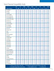
1 = Little to no attack 2 = Weak to moderate attack 3 = Strong attack to complete destruction 4 = Please contact FNPG to ensure Warranty Avoidance<br />
Medium Temp.C NBR HNBR ACM VMQ FKM PTFE Medium Temp.C NBR HNBR ACM VMQ FKM PTFE<br />
Accumulator acid (sulfuric acid) 60 3 3 4 4 1 1<br />
Acetaldehyde, with acetic acid, 90/10% 20 3 3 3 3 3 1<br />
Acetamide 20 4 4 4 4 4 1<br />
Acetic acid, aqueous, 25-60% 60 3 3 4 4 4 1<br />
Acetic acid, dqueous, 85% 100 3 3 4 4 4 1<br />
Acetic acid, glacial 60 3 3 4 4 4 1<br />
Acetic anhydride 20 3 3 4 4 4 1<br />
Acetic anhydride 80 3 3 4 4 4 1<br />
Acetone 20 3 3 3 3 3 1<br />
Acetophenone 20 4 4 4 4 4 1<br />
Acetylene 60 1 1 1 1 1 1<br />
Acrylic acid, Ethylester 20 3 3 3 3 3 1<br />
Acrylonitril 60 3 3 4 3 3 1<br />
Adipic acid, aqueous 20 1 1 4 4 1 1<br />
Aero-engine fuels JP3 (MIL-J 5624) 20 1 2 2 3 1 1<br />
Aero-engine fuels JP4 (MIL-J-5624) 20 1 2 2 3 1 1<br />
Aero-engine fuels JP5 (MIL-J-5624) 20 1 2 2 3 1 1<br />
Aero-engine fuels JP6 (MIL-J-25656) 20 1 2 2 3 1 1<br />
Air, oil-containing 80 1 1 1 1 1 1<br />
Air, pure 80 1 1 1 1 1 1<br />
Allyl alcohol 80 2 2 4 4 3 1<br />
Alum, aqueous 60 3 3 4 4 1 1<br />
Alum, aqueous 100 1 1 1 1 1 1<br />
Aluminum sulphate, aqueous 60 1 1 4 4 1 1<br />
Aluminum sulphate, aqueous 100 1 1 4 4 3 1<br />
Ammonia, 100% 20 2 2 4 4 3 1<br />
Ammonia, aqueous 40 1 1 3 2 3 1<br />
Ammonium acetate, aqueous 60 1 1 4 4 3 1<br />
Ammonium carbonate 60 1 1 4 4 3 1<br />
Ammonium chloride, aqueous 60 1 1 4 4 1 1<br />
Ammonium fluoride, aqueous 20 1 1 4 1 1 1<br />
Ammonium fluoride, aqueous 100 1 1 4 4 3 1<br />
Ammonium nitrate, aqueous 60 1 1 4 4 1 1<br />
Ammonium nitrate, aqueous 100 1 1 4 4 1 1<br />
Ammonium phosphate, aqueous 60 1 1 4 4 3 1<br />
Ammonium sulphatae 60 1 1 4 4 1 1<br />
Ammonium sulphate 100 1 1 4 4 3 1<br />
Ammonium sulphide, aqueous 60 1 1 4 4 1 1<br />
Ammonium sulphide, aqueous 100 2 2 4 4 3 1<br />
Amyl acetate 20 3 3 4 4 3 1<br />
Amyl alcohol 60 2 2 4 4 3 1<br />
Aniline 60 3 3 4 3 3 1<br />
Aniline hydrochloride 20 2 2 4 2 1 1<br />
Aniline hydrochloride 100 3 3 4 4 4 1<br />
Anisole 20 3 3 4 4 4 1<br />
Anthraquinone sulphonic acid, aqueous 30 2 2 4 4 4 1<br />
Antifreeze (motor vehicle) 60 1 1 4 1 1 1<br />
Antimony chloride, aqueous 20 1 1 1 1 1 1<br />
Antimony trichloride, anhydrous 60 1 1 4 4 4 1<br />
Aqua regia 20 3 3 3 3 3 1<br />
Arsenic acid, aqueous 60 1 1 4 4 1 1<br />
Arsenic acid, aqueous 100 1 1 4 4 3 1<br />
Asphalt 100 4 4 4 4 4 1<br />
ASTM fuel A 60 1 1 2 3 1 1<br />
ASTM fuel B 60 2 2 3 3 1 1<br />
ASTM fuel C 60 3 3 3 3 1 1<br />
ASTM oil No.1 100 1 1 1 1 1 1<br />
ASTM oil No.2 100 1 1 1 1 1 1<br />
ASTM oil No.3 100 1 2 1 2 1 1<br />
ATE brake fluid 100 3 3 3 1 3 1<br />
ATF oil 100 1 1 3 2 1 1<br />
Barium hydroxide, aqueous 60 1 1 4 4 1 1<br />
Barium salts, aqueous 60 1 1 4 1 1 1<br />
Beef tallow emulsion, sulphonated 20 1 1 4 2 1 1<br />
Beer 20 1 1 1 1 1 1<br />
Benzaldehyde, aqueous 60 3 3 4 4 1 1<br />
Benzene 20 3 3 3 3 2 1<br />
Benzic acid, aqueous 60 1 1 4 1 1 1<br />
Benzyl alcohol 60 4 4 4 2 4 1<br />
Bisulphite lye 50 2 2 4 4 4 1<br />
Bitumen 60 3 3 4 4 1 1<br />
Black lye 100 2 2 4 4 1 1<br />
Blast furnace gas 100 2 2 1 1 1 1<br />
Bleaching lye 60 3 3 4 4 2 1<br />
Bone oil 60 1 1 1 2 1 1<br />
Borax, aqueous 60 1 1 4 1 1 1<br />
Boric acid, aqueous 60 1 1 4 1 1 1<br />
Brake fluids (glycolether) 80 3 3 3 1 4 1<br />
Bromine water, saturated cold 20 3 3 4 4 4 1<br />
Bromine, liquid 20 3 3 4 4 4 1<br />
Bromine, vapor 20 3 3 4 4 4 1<br />
Bromobenzene 20 4 4 4 4 4 1<br />
Bunker oil 60 2 2 4 4 4 1<br />
Butadiene 60 4 4 4 2 1 1<br />
Butane, gaseous 20 1 1 1 4 1 1<br />
Butanediol, aqueous 20 1 1 4 4 2 1<br />
Butanediol, aqueous 60 1 1 4 4 4 1<br />
Butanol, aqueous 20 1 2 2 1 2 1<br />
Butanol, aqueous 60 3 3 4 4 4 1<br />
Butter 20 1 1 4 1 1 1<br />
Butter 80 1 1 4 4 1 1<br />
Butylacetate 20 3 3 4 4 3 1<br />
Butyl alcohol 60 3 3 4 4 4 1<br />
Butyl phenol 20 3 3 3 3 2 1<br />
Butylene glycol 60 1 1 4 1 2 1<br />
Butylene, liquid 20 1 1 4 4 1 1<br />
Butyne diol 20 1 1 4 4 2 1<br />
Butyraldehyde 20 4 4 4 4 4 1<br />
10.3
1 = Little to no attack 2 = Weak to moderate attack 3 = Strong attack to complete destruction 4 = Please contact FNPG to ensure Warranty Avoidance<br />
Medium Temp.C NBR HNBR ACM VMQ FKM PTFE Medium Temp.C NBR HNBR ACM VMQ FKM PTFE<br />
Butyric acid, aqueous 20 1 1 4 4 1 1<br />
Calcium bisulphite, aqueous 20 1 1 4 4 1 1<br />
Calcium chloride, aqueous 100 1 1 4 1 1 1<br />
Calcium hydroxide, aqueous 20 1 1 4 1 1 1<br />
Calcium hypochlorite, aqueous 60 3 3 3 4 2 1<br />
Calcium nitrate, aqueous 40 1 1 4 1 1 1<br />
Calcium phosphate, aqueous 20 1 1 4 1 1 1<br />
Camphor 20 1 1 4 4 2 1<br />
Camphorated oil 20 1 2 4 4 2 1<br />
Carbolinuem 80 3 3 3 3 1 1<br />
Carbolinuem 60 4 4 4 4 4 1<br />
Carbon dioxide, dry 60 1 1 1 1 1 1<br />
Carbon disulphide 20 3 3 4 3 1 1<br />
Carbon monoxide, dry 60 1 1 1 1 1 1<br />
Carbon monoxide, moist 20 1 1 1 1 1 1<br />
Carbon tetrachloride 60 3 3 4 4 1 1<br />
Caustic potash, 50% 60 2 2 3 3 3 1<br />
Caustic soda 20 2 2 3 3 3 1<br />
Cellosolve 20 4 4 4 4 4 1<br />
Chloral hydrate, aqueous 60 3 3 4 4 2 1<br />
Chlroamine, aqueous 20 1 1 4 4 4 1<br />
Chlorethanol 60 3 3 4 4 3 1<br />
Chloric acid, aqueous 80 3 3 4 4 2 1<br />
Chloride of lime, aqueous 60 3 3 4 4 1 1<br />
Chlorine water, saturated 20 3 3 4 4 1 1<br />
Chlorine, dry gaseous 20 3 3 4 4 2 1<br />
Chlorine, liquid 20 3 3 4 4 2 1<br />
chlorine, moist gaseous 20 3 3 4 4 2 1<br />
Chlorobenzene 20 3 3 3 3 2 1<br />
Chlorobromomethane 20 4 4 4 4 2 1<br />
Chloroform 20 3 3 4 4 2 1<br />
Chlorsulphonic acid 20 3 3 3 3 4 1<br />
Chromic acid, gaseous 60 3 3 4 4 1 1<br />
Chromic acid, aqueous 60 3 3 4 4 1 1<br />
Chromic acid/sulphuric acid/water 50/15/35% 40 3 3 4 4 1 1<br />
Citric acid, aqueous 60 1 1 4 4 1 1<br />
Clophen T 64 100 3 3 4 2 1 1<br />
Clopen-A types 100 3 3 4 1 1 1<br />
Coconut fat 80 1 1 1 1 1 1<br />
Coconut fatty alcohol 20 1 1 4 4 1 1<br />
Coconut oil 60 1 1 1 1 1 1<br />
Coconut oil 80 1 1 4 4 1 1<br />
Cod-liver oil 20 1 1 1 1 1 1<br />
Coking-oven gas 80 3 3 4 4 1 1<br />
Copper fluoride, aqueous 50 1 1 4 4 1 1<br />
Copper nitrate, aqueous 60 1 1 4 4 1 1<br />
Copper sulphate, aqueous 60 1 1 4 4 1 1<br />
copper (1) chloride, aqueous 20 1 1 1 1 1 1<br />
Cottonseed oil 20 1 1 4 4 1 1<br />
Cresol, aqueous 45 3 3 4 4 1 1<br />
Crotonaldehyde 20 4 4 4 4 3 1<br />
Cyclohexane 20 1 1 2 2 1 1<br />
Cyclohexanol 20 1 1 4 4 4 1<br />
cyclohexanone 20 3 3 4 4 4 1<br />
Cyclohexylamine 20 3 3 4 4 3 1<br />
Decahydronaphthalene (Decalin) 20 3 3 2 4 2 1<br />
Decahydronaphthalene (Decalin) 60 3 3 2 4 2 1<br />
Desmodur T 20 3 3 3 4 4 1<br />
Desmophen 2000 80 1 1 4 4 4 1<br />
Detergent, synthetic 60 1 1 3 4 1 1<br />
Detergents 100 1 1 4 4 2 1<br />
Dextrin, aqueous 60 1 1 4 1 1 1<br />
Diacetone alcohol 20 2 2 4 4 4 1<br />
Dibenzyl ether 20 3 3 4 4 3 1<br />
Dibutyl ether 20 3 3 4 4 3 1<br />
Dibutyl phthalate 20 3 3 4 1 1 1<br />
Dibutyl phthalate 60 3 3 4 1 2 1<br />
Dibutyl sebacate 60 3 3 4 2 4 1<br />
Dichloracetic acid 60 3 3 4 4 3 1<br />
Dichlorethane 20 3 3 3 3 2 1<br />
Dichlorethylene 20 3 3 4 4 2 1<br />
Dichlorobenzene 20 3 3 4 4 1 1<br />
Dichlorobutylene 20 3 3 4 4 2 1<br />
Dichloromethane 20 3 3 3 3 1 1<br />
Diesel fuel 60 1 2 2 2 1 1<br />
Diethyl ether 20 3 3 4 4 3 1<br />
Diethyl sebacate 20 3 3 4 4 2 1<br />
Diethylamine 20 2 2 4 4 3 1<br />
Diethylene glycol 20 1 1 4 1 1 1<br />
Diglycolic acid, aqueous 60 2 2 4 4 1 1<br />
Dihexyl phthalate 60 3 3 4 4 3 1<br />
Diisobutyl ketone 60 3 3 4 4 3 1<br />
Dimethyl ether 20 3 3 4 4 3 1<br />
Dimethylamine 20 3 3 4 4 3 1<br />
Dimethylformamide 60 3 3 4 3 3 1<br />
Dinonyl phthalate 30 3 3 4 4 3 1<br />
Dioctyl phthalate 60 3 3 4 4 3 1<br />
Dioctyl sebacate 60 3 3 4 4 3 1<br />
Dioxane 60 3 3 4 4 3 1<br />
Dipentene 20 2 2 4 4 1 1<br />
Diphenyl 20 3 3 4 4 1 1<br />
Diphenyl oxide 100 4 4 4 4 4 1<br />
Engine oils 100 1 1 1 2 1 1<br />
Epichlorhydrin 20 4 4 4 4 3 1<br />
Essential Oils 20 3 3 4 4 2 1<br />
Ethane 20 1 1 1 2 1 1<br />
Ethanol 20 1 1 4 1 4 1<br />
Ethanol 80 3 3 4 4 3 1<br />
Ethanol w/ acetic acid (fermentation mixture) 20 3 3 4 4 3 1<br />
Ethanol w/ acetic acid (fermentation mixture) 60 3 3 4 4 3 1<br />
Ethyl acetate 60 3 3 4 1 3 1<br />
Ethyl acrylate 20 3 3 3 3 3 1<br />
10.3
1 = Little to no attack 2 = Weak to moderate attack 3 = Strong attack to complete destruction 4 = Please contact FNPG to ensure Warranty Avoidance<br />
Medium Temp.C NBR HNBR ACM VMQ FKM PTFE Medium Temp.C NBR HNBR ACM VMQ FKM PTFE<br />
Ethyl benzene 20 3 3 3 3 2 1<br />
Ethyl chloride 20 2 2 3 3 2 1<br />
Ethyl ether 20 3 3 3 3 3 1<br />
Ethylene chloride 20 2 2 3 3 2 1<br />
Ethylene diamine 60 3 3 3 3 3 1<br />
Ethylene glycol 100 1 1 4 2 1 1<br />
Ethylene trichloride 20 4 4 4 4 4 1<br />
Exhaust gasses,containing carbon dioxide 60 1 1 1 1 1 1<br />
Exhaust gases, containing carbon monoxide 60 1 1 1 1 1 1<br />
Exhaust gases, containing hydrogen chloride 60 2 2 4 4 1 1<br />
Exhaust gases,containing hydrogen fluoride, traces60 1 1 4 4 1 1<br />
Exhaust gases, containing nitrous gases, traces 60 4 4 3 3 1 1<br />
Exhaust gases, containing nitrous gases, traces 80 4 4 3 3 1 1<br />
Exhaust gases, containing sulphur dioxide 60 2 2 4 4 1 1<br />
Exhaust gases, containing sulphuric acid 60 2 2 4 4 1 1<br />
Exhaust gases, containing sulphuric acid 80 3 3 4 4 1 1<br />
Fats; mineral, animal or vegetable 80 1 1 1 1 1 1<br />
Fatty acids 100 2 2 4 4 1 1<br />
Fatty alcohol 20 1 1 1 1 1 1<br />
Fertilizer salt, aqueous 60 1 1 4 1 1 1<br />
Fish oil 20 1 1 1 1 1 1<br />
Fluorine, dry 60 3 3 4 4 4 1<br />
Fluorobenzene 20 3 3 3 3 2 1<br />
Fluorocarbon oils 100 4 4 4 1 4 1<br />
Fluorosilicic acid 100 4 4 4 4 4 1<br />
Fluorosilicic acid, aqueous 60 1 1 4 4 1 1<br />
Formaldehyde, aqueous 60 2 2 3 4 4 1<br />
Formamide 60 3 3 4 4 2 1<br />
Formic acid, aqueous 60 3 3 4 4 4 1<br />
Freon according…<br />
Fruit juice 100 2 2 4 1 1 1<br />
Furane 20 4 4 4 4 3 1<br />
Furfural 20 3 3 4 4 4 1<br />
Furfuryl alcohol 20 4 4 4 4 4 1<br />
Furnace gas, dry 60 3 3 4 1 1 1<br />
Gas liquor 40 1 1 3 3 1 1<br />
Gas oil 80 1 1 1 2 1 1<br />
Gasohol 20 3 3 3 3 4 1<br />
Gelatine, aqueous 40 1 1 2 1 1 1<br />
Glaubers salt, aqueous (sodium sulphate) 20 1 1 2 4 1 1<br />
Glucose, aqueous 80 1 1 4 1 1 1<br />
Glue 20 1 1 1 1 1 1<br />
Glycerol chlorhydrin 60 3 3 4 4 4 1<br />
Glycerol, aqueous 100 1 1 4 1 1 1<br />
Glycine, aqueous, 10% 40 2 2 4 4 1 1<br />
Glycol, aqueous 100 1 1 4 2 2 1<br />
Glycolic acid, aqueous, 37% 20 1 1 4 1 1 1<br />
Grape sugar, aqueous 80 1 1 4 1 1 1<br />
Heating oil, mineral-oil based 60 1 1 1 2 1 1<br />
Henkel P3 solution 100 1 1 4 4 4 1<br />
Heptane 60 1 1 1 3 1 1<br />
Hexachlorobutadiene 20 3 3 4 4 1 1<br />
Hexachlorobutadiene 20 4 4 4 4 1 1<br />
Hhexaldehyde 20 3 3 4 4 4 1<br />
Hexane 60 1 1 1 3 1 1<br />
Hexane triol 20 1 1 4 1 1 1<br />
Hexene 20 2 2 1 4 1 1<br />
Hydraulic fluids, hydraulic oils 80 1 1 1 2 1 1<br />
Hydraulic fluids, oil-in-water emulsions HFA 55 1 1 4 4 1 1<br />
Hydraulic fluids, phosphoric acid ester HFD 80 3 3 3 3 4 1<br />
Hydraulic fluids, polyglycol-water emulsions 60 1 1 4 1 1 1<br />
Hydraulic fluids, water-in oil emoulsions HFB 60 4 4 4 4 1 1<br />
Hydrazine hydrate 20 2 2 4 4 4 1<br />
Hydrobromic acid, aqueous 60 2 2 4 4 4 1<br />
Hydrochloric acid, concentrated 80 3 3 4 4 1 1<br />
Hydrochloric acid, concentrated 20 3 3 4 4 1 1<br />
Hydrochloric acid, dilute 20 1 2 4 4 1 1<br />
Hydrofluoric acid, concentrated 20 4 4 4 4 4 1<br />
Hydrogen 20 1 1 1 1 1 1<br />
Hydrogen chloride gas 60 3 34 4 1 1<br />
Hydrogen peroxide, aqueous 20 3 3 4 2 1 1<br />
Hydrogen sulphide, aqueous 60 2 2 4 4 1 1<br />
Hydrogen sulphide, dry 60 2 2 4 4 1 1<br />
Hydroquinone, acqueous 20 1 1 2 4 1 1<br />
Hydrosulphite, aqueous 40 2 2 4 4 4 1<br />
Hydroxylamine sulphate, aqueous 35 1 1 4 1 4 1<br />
Ink 20 1 2 1 1 2 1<br />
Iodine, tincture 20 1 1 4 2 1 1<br />
Iodoform 20 4 4 4 4 1 1<br />
Iron (III) chloride, aqueous 40 1 1 4 4 1 1<br />
Isobutanol 20 2 2 3 1 1 1<br />
Isoctane 20 1 1 1 2 1 1<br />
Isophorone 20 4 4 4 4 4 1<br />
Isopropanol 60 2 2 3 1 2 1<br />
Isopropyl acetate 80 3 3 3 3 3 1<br />
Isopropyl chloride 20 3 3 3 3 1 1<br />
Isopropyl ether 60 3 3 3 3 3 1<br />
Kerossene 20 1 2 1 2 1 1<br />
Lactam 80 3 3 4 4 3 1<br />
Lactic acid, aqueous 40 1 1 4 4 1 1<br />
Lanolin (wool fat) 60 1 1 1 1 1 1<br />
Laughing gas (nitrous oxide) 20 1 1 1 1 1 1<br />
Lauryl alcohol 20 1 1 4 4 1 1<br />
Lavender oil 20 2 2 2 4 1 1<br />
Lead acetate, aqueous 60 1 2 4 4 1 1<br />
Lead acetate, aqueous 100 1 2 4 4 3 1<br />
Lead nitrate, aqueous 20 1 1 4 4 1 1<br />
Lemon juice, undiluted 20 1 1 4 1 4 1<br />
Linoleic acid 20 2 2 4 2 2 1<br />
Linseed oil 60 1 1 1 1 1 1<br />
Liquers 20 1 1 1 1 1 1<br />
Lithium bromide, aqueous 1 1 4 1 1 1 1<br />
Lithium chloride, aqueous 20 1 1 1 1 1 1<br />
Machine oil, mineral 80 1 1 1 2 1 1<br />
Magnesium chloride, aqueous 100 1 1 3 4 1 1<br />
Magnesium sulphate, aqueous 100 1 1 3 4 1 1<br />
Maize oil (corn oil) 60 1 1 4 4 1 1<br />
Maleic acid, aqueous 100 1 1 4 4 1 1<br />
10.3
1 = Little to no attack 2 = Weak to moderate attack 3 = Strong attack to complete destruction 4 = Please contact FNPG to ensure Warranty Avoidance<br />
Medium Temp.C NBR HNBR ACM VMQ FPM PTFE<br />
Medium Temp.C NBR HNBR ACM VMQ FKM PTFE Medium Temp.C NBR HNBR ACM VMQ FKM PTFE<br />
Maleic anhydride 60 4 4 4 4 1 1<br />
Margarine 80 1 1 1 1 1 1<br />
Marsh gas (methane) 20 1 1 1 1 1 1<br />
Menthol 60 3 3 4 4 2 1<br />
Mercury 60 1 1 1 1 1 1<br />
Mercury salts, aqueous 60 1 1 4 1 1 1<br />
Mesityl oxide 4 4 4 4 4 1<br />
Methane 20 1 1 1 1 1 1<br />
Methanol 60 2 2 4 1 4 1<br />
Methoxy butanol 60 1 1 4 4 1 1<br />
Methyl acrylate 20 3 3 3 3 3 1<br />
Methyl bromide 20 3 3 3 3 1 1<br />
Methyl chloride 20 3 3 4 4 2 1<br />
Methyl ethyl ketone 20 3 3 3 3 3 1<br />
Methyl isobutyl ketone 20 3 3 3 3 3 1<br />
Methyl methacrylate 20 3 3 3 3 3 1<br />
Methylamine, aqueous 20 3 3 4 4 3 1<br />
Methylene chloride 20 3 3 3 3 1 1<br />
Milk 20 1 1 4 1 1 1<br />
Milk of lime 80 3 3 4 4 1 1<br />
Mineral oil 100 1 1 1 2 1 1<br />
Mineral water 60 1 1 4 1 1 1<br />
Mixed acid I (sulphuric acid/nitric acid/water) 20 3 3 3 3 1 1<br />
Mixed acid II (sulphuric acid/phosphoric acid/water) 40 3 3 4 4 1 1<br />
Molasses 100 1 1 4 4 1 1<br />
Monobromobenzene 20 3 3 3 3 2 1<br />
Monochloracetic acid 60 2 2 4 4 4 1<br />
Monochloracetic aciid, ethyl ester 60 3 3 3 3 2 1<br />
Monochloracetic acid, methyl ester 60 3 3 3 3 2 1<br />
Morpholine 60 3 3 4 4 4 1<br />
Myristyl alcohol 20 1 1 1 1 1 1<br />
n-Propanol 60 2 2 4 1 2 1<br />
Naftolen ZD 20 2 2 4 4 1 1<br />
Naphtha 20 3 3 2 4 1 1<br />
Naphthalene 60 3 3 4 4 1 1<br />
Naphthoic acid 20 2 2 4 4 1 1<br />
Natural gas 20 1 1 4 1 1 1<br />
Natural gas, crude 20 1 1 1 1 1 1<br />
Nickel acette, aqueous 20 1 1 4 4 4 1<br />
Nickel chloride, aqueous 20 1 1 4 4 1 1<br />
Nickel sulphate, aqueous 60 1 1 4 4 1 1<br />
Nitric acid, dilute 80 2 2 4 2 1 1<br />
Nitric acid, fuming 60 3 3 4 4 3 1<br />
Nitric, concentrated 80 3 3 4 4 3 1<br />
Nitrobenzene 60 3 3 3 3 1 1<br />
Nitrogen 20 1 1 1 1 1 1<br />
Nitrogen dioxide 20 4 4 4 3 4 1<br />
Nitroglycerine 20 3 3 4 4 1 1<br />
Nigroglycol, aqueous 20 3 3 4 4 1 1<br />
Nitromethane 20 3 3 3 3 3 1<br />
Nitropropage 20 3 3 3 3 3 1<br />
Nitrous gases (oxides of nitrogen) 20 3 3 3 3 1 1<br />
o-Nitrotoluene 60 3 3 3 3 3 1<br />
Octane 20 4 4 4 4 1 1<br />
Octyl alcohol 20 2 2 4 2 1 1<br />
Octyl cresol 20 4 4 3 3 2 1<br />
Oil, crude 20 1 2 1 2 1 1<br />
Oleum, 10% 20 3 3 3 3 1 1<br />
Oleyl alcohol 20 1 1 1 1 1 1<br />
Olive oil 60 1 1 1 1 1 1<br />
Oxalic acid, aqueous 100 3 3 4 4 1 1<br />
Ozone 20 4 2 2 1 1 1<br />
Palm kernel fatty acid 60 1 1 4 4 1 1<br />
Palmitic acid 60 2 2 4 4 1 1<br />
Paraffin 60 1 1 4 4 1 1<br />
Paraffin emulsions 40 1 1 1 1 1 1<br />
Paraffin oil 60 1 1 1 1 1 1<br />
Pectin 20 1 1 1 1 1 1<br />
Pentachlorodiphenyl 60 3 3 4 4 4 1<br />
Pentane 20 1 1 4 4 1 1<br />
Peracetic acid
1 = Little to no attack 2 = Weak to moderate attack 3 = Strong attack to complete destruction 4 = Please contact FNPG to ensure Warranty Avoidance<br />
Medium Temp.C NBR HNBR ACM VMQ FKM PTFE Medium Temp.C NBR HNBR ACM VMQ FKM PTFE<br />
Piperidine 4 4 4 4 4 4 1<br />
Potash, aqueous 40 1 1 4 1 1 1<br />
Potassium acetate, aqueous 20 1 2 4 4 1 1<br />
Potassium bisulphate, aqueous 40 1 1 4 4 1 1<br />
Potassium borate, aqueous 60 1 1 4 4 1 1<br />
Potassium bromate, 10% 60 1 2 4 4 1 1<br />
Potassium bromide, aqueous 60 1 1 4 4 1 1<br />
Potassium carbonate, aqueous 40 1 1 4 1 1 1<br />
Potassium chlorate, aqueous 60 3 3 4 4 1 1<br />
Potassium chloride, aqueous 60 1 1 4 4 1 1<br />
Potassium chromate, aqueous 20 2 2 4 4 1 1<br />
Potassium cyanide, aqueous 40 1 1 4 1 1 1<br />
Potassium cyanide, aqueous 80 2 2 4 1 1 1<br />
Potassium dichromate, aqueous 40% 20 2 2 4 4 1 1<br />
Potassium idodide, aqueous 60 1 1 4 4 1 1<br />
Potassium nitrate, aqueous 60 1 1 4 4 1 1<br />
Potassium perchloraate, aqueous 80 3 3 4 4 1 1<br />
Potassium permanganate, aqueous 40 3 3 4 4 1 1<br />
Potassium persulphate, aqueous 60 3 3 4 4 1 1<br />
Potassium sulphate, aqueous 60 1 1 4 4 1 1<br />
Propane, liquid gaseous 20 1 1 1 1 1 1<br />
Propargyl alcohol, aqueous 60 1 1 4 4 1 1<br />
Propionic acid, aqueous 60 1 1 4 4 1 1<br />
Propylene glycol 60 1 1 4 4 1 1<br />
Propylene oxide 20 3 3 4 4 4 1<br />
Prussic acid (hydrocyanic acid) 20 4 4 4 1 4 1<br />
Pyridine 20 3 3 3 3 3 1<br />
Pyrrole 20 4 4 4 2 4 1<br />
Rapeseed oil 20 2 2 2 4 1 1<br />
Refrigerant<br />
Sagrotan 20 2 2 4 1 1 1<br />
Salicylic acid 20 1 1 4 4 1 1<br />
Salt water 20 1 1 4 4 1 1<br />
Sea water 20 1 1 4 1 1 1<br />
Silicic acid, aqueous 60 1 1 4 4 1 1<br />
Silicone grease 20 1 1 1 3 1 1<br />
Silicone oil 20 1 1 1 1 1 1<br />
Silver nitrate, aqueous 100 2 2 4 4 1 1<br />
Silver salts, aqueous 60 2 2 4 1 1 1<br />
skydrol 20 3 3 3 3 3 1<br />
Soap solution, aqueous 20 1 1 4 4 1 1<br />
Soda, aqueous 60 2 2 4 1 1 1<br />
Sodium benzoate,aqueous 40 1 1 4 4 1 1<br />
Sodium bicarbonate, aqueous 60 1 1 4 4 1 1<br />
Sodium bisulphite, aqueous 100 1 1 4 4 1 1<br />
Sodium chlorate 20 3 3 4 4 1 1<br />
Codium chloride 100 1 1 4 4 1 1<br />
Sodium hypochlorite, aqueous 20 2 2 4 4 1 1<br />
Sodium nitrate, aqueous 60 1 1 4 4 1 1<br />
Sodium nitrite 60 2 2 4 4 1 1<br />
Sodium phosphate, aqueous 60 1 1 4 4 1 1<br />
Sodium silicate, aqueous 60 1 1 4 4 1 1<br />
Sodium sulphate, aqueous 60 1 1 4 4 1 1<br />
Sodium sulphide 40 1 1 4 4 1 1<br />
Sodium thiosulphate 60 3 3 4 4 1 1<br />
Spermaceti 20 1 1 4 4 1 1<br />
Spindle oil 60 1 1 1 1 1 1<br />
Starch syrup 60 1 1 4 4 1 1<br />
Starch aqueous 60 1 1 1 1 1 1<br />
Steam 130 3 3 4 3 4 1<br />
Stearic acid 60 1 1 1 1 1 1<br />
Stoddard solvent 20 1 1 1 4 1 1<br />
Styrene 20 3 3 4 3 2 1<br />
Succinic acid, aqueous 60 1 1 4 4 1 1<br />
Sugar syrup 60 1 1 4 4 1 1<br />
Sulphur 60 4 4 4 4 1 1<br />
Sulphur chloride 20 3 3 4 4 1 1<br />
Sulphur dioxide, aqueous 60 3 3 4 4 1 1<br />
Sulphur dioxide,dry 80 3 3 4 4 1 1<br />
Sulphur dioxide, liquid 60 3 3 4 4 1 1<br />
Sulphur hexafluoride 20 1 1 1 1 1 1<br />
Sulphuric acid, concentrated 50 3 3 4 3 1 1<br />
Sulphuric acid, dilute 20 2 2 4 4 1 1<br />
sulphuryl chloride 20 3 3 4 4 1 1<br />
Tallow 60 1 1 4 4 1 1<br />
Tannic acid 60 1 1 2 1 1 1<br />
Tannin 40 2 2 4 4 1 1<br />
Tanning extract 20 1 1 2 1 1 1<br />
Tar 20 3 3 4 4 4 1<br />
Tar oil 20 3 3 4 4 4 1<br />
Tartaric acid, aqueous 60 1 1 4 1 1 1<br />
Test media ASTM oil No.1 100 1 1 1 1 1 1<br />
Test media ASTM oil No. 2 100 1 1 1 2 1 1<br />
Test media ASTM oil No. 3 100 1 2 1 3 1 1<br />
Tetrachlorethane 60 3 3 4 4 2 1<br />
Tetrachlorethylene 60 3 3 4 4 2 1<br />
Tetraethyl lead 20 2 2 4 4 1 1<br />
Tetrahydrofuran 20 3 3 4 4 3 1<br />
Tetrahydronaphthalene (tetralin) 20 3 3 4 4 1 1<br />
Thionyl chloride 20 3 3 4 4 1 1<br />
Thiophene 60 3 3 4 4 3 1<br />
Tin (II) chloride, aqueous 80 1 1 4 4 1 1<br />
Titanium tetrachloride 20 1 1 2 2 2 1<br />
Toluene 20 3 3 3 3 2 1<br />
Town gas, benzene free 20 1 1 1 1 1 1<br />
Transformer oil 60 1 2 1 2 1 1<br />
Transmission fluid, Type A 20 1 1 1 2 1 1<br />
Triacetin 20 2 2 4 4 4 1<br />
Tributoxyethyl phosphate 20 3 3 4 4 2 1<br />
Tributyl phosphate 60 3 3 4 4 2 1<br />
Trichloracetic acid, aqueous 60 2 2 4 4 3 1<br />
Trichlorethyl phosphage 20 3 3 4 4 3 1<br />
Trichlorethylene 20 3 3 4 3 2 1<br />
Tricresyl phosphate 60 3 3 4 4 2 1<br />
Triethanolamine 20 3 3 4 4 4 1<br />
Triethyl aluminum 20 4 4 4 4 2 1<br />
Triethyl borane 20 4 4 4 4 1 1<br />
Triglycoll 20 1 1 4 4 1 1<br />
10.3
1 = Little to no attack 2 = Weak to moderate attack 3 = Strong attack to complete destruction 4 = Please contact FNPG to ensure Warranty Avoidance<br />
Medium Temp.C NBR HNBR ACM VMQ FKM PTFE Medium Temp.C NBR HNBR ACM VMQ FKM PTFE<br />
Trimethylol propane, aqueous 100 3 3 4 4 1 1<br />
Trinitrotoluene 20 4 4 4 4 2 1<br />
Trioctyl phosphate 60 3 3 4 4 2 1<br />
Trisodium phosphage 20 1 1 4 1 1 1<br />
Turpentine 60 2 2 4 4 1 1<br />
Turpentine, oil of 20 2 2 4 4 1 1<br />
Urea, aqueous 60 1 1 4 4 1 1<br />
Vaseline 60 1 1 1 2 1 1<br />
Vaseline oil 60 1 1 1 2 1 1<br />
Vinyl acetate 20 4 4 4 4 4 1<br />
Vinyl chloride, liquid 20 4 4 4 4 4 1<br />
Water 100 1 1 3 2 1 1<br />
Wax alcohol 60 1 2 4 4 1 1<br />
Whisky 20 1 1 4 1 1 1<br />
White lye 100 2 2 4 4 3 1<br />
White oil 20 1 1 1 1 1 1<br />
White spirit 60 1 2 1 4 1 1<br />
Wine 20 1 1 4 1 1 1<br />
Xylamon (wood perservatives) 20 3 3 3 4 2 1<br />
Xylene 20 3 3 3 3 2 1<br />
yeast,aqueous 20 1 1 4 1 1 1<br />
Zeolites 20 1 1 1 1 1 1<br />
Zinc acetate 20 2 2 1 1 1 1<br />
<strong>Radial</strong> <strong>Shaft</strong> <strong>Seal</strong> Styles<br />
<strong>Simrit</strong> style designations...<strong>Simrit</strong> Europe<br />
BA Rubber covered-spring loaded<br />
B1 Metal O.D.-spring loaded<br />
B2 Double metal case-spring loaded<br />
D Flex section<br />
D1 Profile to standard<br />
DRL Left handed helix<br />
DRR Right handed helix<br />
DRW Bi-directional helix<br />
F Ready molded lip<br />
FG Protected spring<br />
HD High pressure<br />
J <strong>Seal</strong>ing lip on O.D.<br />
L Low friction seal<br />
LD Profile <strong>Seal</strong><br />
SD Silicone profile<br />
SL Ready molded dust lip<br />
U Universal profile<br />
UD Triangle profile<br />
X1 O.D. specifications<br />
X2 <strong>Seal</strong>ing lip specifications<br />
X3 Ready molded helix<br />
X4 Dust lip inside sealing lip<br />
X7 Grooved O.D.<br />
BL With metal part<br />
OB Without metal part<br />
NIBL Stainless steel metal part<br />
MSBL Brass metal part<br />
ALUBL Aluminum metal part<br />
OF Without spring<br />
NIF Stainless steel spring<br />
BRF Bronze spring<br />
STF Steel spring<br />
SF Special Feature<br />
<strong>Simrit</strong> style designations...NOK<br />
S Spring loaded single lip<br />
T Auxiliary Lip(s) spring loaded main lip<br />
V Non-spring loaded single lip<br />
K Auxiliary lip and non-spring loaded main lip<br />
D Double lip, both spring loaded<br />
A<br />
B<br />
C<br />
M<br />
Assembled seal - metal O.D.<br />
Metal O.D. (non-assembled)<br />
Rubber covered O.D.<br />
Combination assembled seal<br />
3 Auxiliary lip directed toward main lip<br />
4 Two stepped main lip<br />
6 Three stepped main lip<br />
9 Side lip<br />
L Reciprocal special outward dust lip<br />
V Medium pressure main lip<br />
2 Rubber bond area minimized with Metal O.D.<br />
5 Flange<br />
J PTFE lip member<br />
K Non-woven fabric lip<br />
1 Lip reinforcing retainer for single lip seal<br />
N High pressure double lip seal with lip retainer<br />
H Hydrodynamic aid to main lip (Helix)<br />
11.0.5
Glossary of Terms<br />
Assembled spring – Inside Diameter:<br />
The inner diameter of the garter spring,<br />
with the ends securely joined.<br />
Axial clearance: The gap between the toe<br />
face to the head section and the inside<br />
surface of the inner case.<br />
Circumferential surface roughness:<br />
Surface roughness of a shaft measured in<br />
a direction (plane) normal to the<br />
centerline axis.<br />
Cocked assembly: An installation in which<br />
the plane of the outside seal face is not<br />
perpendicular to the shaft axis.<br />
Coil: One turn of the coiled wire garter spring.<br />
Contact approach angle: Synonym:<br />
Angle, Outside lip<br />
Contact line: The line of intersection between<br />
the outside and inside lip surfaces of a<br />
radial shaft seal. In a cross-section view,<br />
this intersection is illustrated as a point.<br />
Contact line height: The axial distance from<br />
the outside seal face to the lip contact<br />
line.<br />
Contact width: The width of the lip contact<br />
area of a radial shaft seal, measured in<br />
the axial direction.<br />
Crack: A sharp break or fissure in the sealing<br />
element.<br />
Cut: A deep discontinuity in the seal material<br />
whereby no material is removed.<br />
Deformation: A stress induced change of<br />
form or shape.<br />
Dynamic Run-out: Twice the distance the<br />
center of the shaft is displaced from the<br />
center of rotation and expressed in TIR.<br />
That Run-out to which the seal lip is<br />
subjected due to the outside diameter of<br />
the shaft not rotating in a true circle.<br />
Synonym: <strong>Shaft</strong> Run-out<br />
Elastomer: An elastic rubber like substance.<br />
Extrusion: Permanent displacement of part of<br />
a seal into a gap, under the action of fluid<br />
pressure.<br />
Fluid side: The side of the seal which in<br />
normal use faces toward the fluid being<br />
sealed.<br />
Functional lip diameter: The apparent<br />
inner diameter of the seal when the seal<br />
case is concentric with the outer diameter<br />
of the sizing mandrel in an air gage, light<br />
box, or similar inspection equipment.<br />
Garter spring: A helically coiled wire with<br />
its’ ends connected to form a ring. It is<br />
used in tension for maintaining a radial<br />
sealing force between element of a radial<br />
lip seal and a shaft.<br />
Heel: Synonym: Heel section<br />
Heel section: The portion of a lip seal which<br />
is attached to the seal case and bounded<br />
by the flex section and the outside face.<br />
Helix contact width: The axial width of that<br />
portion of the contact surface of a helix<br />
seal which is formed by the helical ribs. It<br />
is equal to the total axial width of the<br />
contact surface minus the width of the<br />
static lip.<br />
Housing bore: A cylindrical surface which<br />
mates with the outside diameter of the<br />
outer seal case.<br />
Hydrodynamic seal: A dynamic sealing<br />
device which utilizes the viscous shear<br />
and inertia forces of the fluid; imparted by<br />
a helically grooved or ribbed seal lip, to<br />
generate a pressure differential that<br />
opposes fluid flow.<br />
Inclusion: Foreign matter included in the seal<br />
material.<br />
Inner case: A rigid, cup-shaped component of<br />
a seal assembly, which is placed inside<br />
the outer seal case. It has one or more of<br />
the following functions: reinforcing<br />
member, shield, spring retainer, lipclamping<br />
device.<br />
12.0
Inside face: That surface of the inner case<br />
which faces, and is usally in contact with,<br />
the fluid being sealed.<br />
Inside single lip angle: The angle between<br />
the inside lip surface and the axis of the<br />
seal case.<br />
Lip diameter: The inner diameter of the seal<br />
lip, measured with the spring installed.<br />
Lip force: The radial force exerted by an<br />
extension spring and/or lip of a seal on the<br />
mating shaft. Lip force is expressed as<br />
force per unit of shaft circumference.<br />
Lip height: The axial distance from the outside<br />
seal face to the toe face.<br />
Lip ID to ID eccentricity: See: <strong>Radial</strong> Wall<br />
Variance<br />
Lip opening pressure: The pressure necessary<br />
for flowing air at 10000 cc/min.<br />
between the contact surface of a radial lip<br />
seal and shaft-size mandrel under the<br />
following conditions: the seal case outer<br />
diameter clamped to be concentric with the<br />
mandrel and the pressurized air applied to<br />
the outside lip surface.<br />
Lip seal: An elastomeric seal which prevents<br />
leakage in dynamic and static applications<br />
by reason of controlled interference between<br />
the seal lip and the mating surface.<br />
Lubricant starvation: Lack of proper lubrication<br />
at the seal interface which may cause<br />
premature wear and early failure.<br />
Offset: The radial distance between the axis of<br />
the seal bore and axis of shaft rotation.<br />
Oil seal: A seal designed primarily for the<br />
retention of oil.<br />
Outer case: the outer thin-wall rigid structure of<br />
the lip seal assembly which contains the<br />
inner case, the primary seal ring, the spring<br />
and the secondary seal.<br />
Outside lip angle: The angle between the<br />
outside lip and the axis of the seal case.<br />
Plunge ground: The surface texture of shaft<br />
or wear sleeve produced by presenting the<br />
grinding wheel perpendicular to the<br />
rotating shaft without axial motion.<br />
Primary lip: The normally flexible elastomeric<br />
component of a shaft seal assembly, which<br />
rides against the rotating surface and<br />
affects the seal.<br />
<strong>Radial</strong> lip seal: A type of seal which features<br />
a flexible sealing member referred to as a<br />
lip. The lip is usually an elastomeric<br />
material. It exerts radial sealing pressure<br />
on a mating shaft in order to retain fluids<br />
and/or exclude foreign matter.<br />
<strong>Radial</strong> load: The total force (load) acting on<br />
the seal lip which tends to maintain<br />
contact of the lip on the shaft. It is the sum<br />
of the forces developed from seal interference<br />
and the garter spring.<br />
<strong>Radial</strong> wall variation: the difference<br />
between the minimum and the maximum<br />
radial wall dimensions when measured<br />
around 360 degrees, of the seal lip.<br />
Rib: A long, narrow projection which is<br />
normally triangular in cross-section and<br />
which is molded into the outside lip<br />
surface of a helical seal. It is oriented at<br />
an angle to the shaft axis. One end of the<br />
rib forms part of the seal-lip contact<br />
surface.<br />
Rough trim: A trimmed surface with irregularities<br />
on the outside and inside lip surfaces<br />
in the immediate vicinity of the contact line<br />
Roughness: Irregularities in shaft surface<br />
texture which result from the production<br />
process. (See SAE J448a [June, 1963].)<br />
Scratch: A shallow discontinuity in the seal<br />
material whereby no material is removed.<br />
<strong>Seal</strong> assembly: A group of parts, which<br />
includes sealing surfaces, provisions for<br />
initial loading, and a secondary sealing<br />
mechanism which accommodates the<br />
radial movement necessary for installation<br />
and operation.<br />
12.0
<strong>Seal</strong> case: A rigid member to which the seal<br />
lip is attached.<br />
<strong>Seal</strong> outer diameter: The external diameter<br />
of a lip-seal assembly.<br />
<strong>Shaft</strong> eccentricity: The radial distance in<br />
which the geometric center of a shaft is<br />
displaced from the axis of shaft rotation.<br />
<strong>Shaft</strong> lead: Spiral grooves on a shaft surface<br />
caused by relative axial movement of<br />
grinding wheel to shaft.<br />
<strong>Shaft</strong> Run-out: See: Dynamic Run-out<br />
<strong>Shaft</strong> surface finish: See: <strong>Shaft</strong> Surface<br />
Texture<br />
<strong>Shaft</strong> surface texture: A term used to<br />
describe the quality, appearance or<br />
characteristics of the shaft surface resulting<br />
from operations, such as grinding, polishing,<br />
burnishing, etc. (See SAE J448a<br />
[June, 1963]).<br />
Slip stick: A friction related phenomena in<br />
which the sealing element tends to adhere<br />
and rotate with the shaft surface momentarily<br />
until the elastic characteristics of the<br />
sealing element overcome the adhesive<br />
force, causing the seal lip to lose connection<br />
with the rotating shaft long enough to<br />
allow leakage. This cycle repeats itself<br />
continuously and is normally associated<br />
with non-lubricated and boundary-lubricated<br />
conditions<br />
Spiral trim: A trimmed surface which has a<br />
spiral pattern.<br />
Spring groove: A depression formed in the<br />
head section of the seal. It is generally<br />
semicircular in form and serves to accommodate<br />
and locate the garter spring.<br />
Trim: The removal of superfluous parts from a<br />
molded product, usually removal of<br />
parting line flash or feed spews.<br />
Trim cut: Damage to the elastomeric portion of<br />
the seal during trimming.<br />
Trimming angle: The angle between the<br />
trimmed face of a seal lip and the seal<br />
axis.<br />
Trimmed lip diameter: The lip diameter in<br />
the free state (no spring) developed by<br />
knife trimming the molded portion of the<br />
sealing element to form the contact line.<br />
Unbonded flash: Flash which does not<br />
adhere to the mating material.<br />
Unirotational seal: A seal, designed for<br />
applications having a single direction of<br />
shaft rotation.<br />
Unitized seal: A seal assembly in which all<br />
components necessary for accomplishing<br />
the complete sealing function are retained<br />
in a single package.<br />
Under-cure: A degree of cure less than<br />
desired.<br />
Volume swell: Increase in physical size<br />
caused by the swelling action of a liquid,<br />
generally expressed as a percent of the<br />
original volume.<br />
Wear sleeve: A replacement metal ring<br />
generally used in assemblies to eliminate<br />
expensive shaft replacement caused by<br />
grooving that may occur at the seal-shaft<br />
interface.<br />
Weepage: A minute amount of liquid leakage<br />
by a seal.<br />
Spring outside coil diameter: The outer<br />
diameter of an individual helical coil of a<br />
garter spring.<br />
Spring retaining lip: The portion of the<br />
primary lip that restricts the axial movement<br />
of the extension spring from a<br />
predetermined position.<br />
12.0
Conversion Charts<br />
Fraction - mm Medium Temp.C NBR HNBR ACM VMQ FPM PTFE<br />
Fraction Decimal 0 1 2 3 4 5 6 7 8 9 10<br />
0 25.400 50.800 76.200 101.600 127.000 152.400 177.800 203.200 228.600 254.000<br />
1/64 0.016 0.397 25.797 51.197 76.597 101.997 127.397 152.797 178.197 203.597 228.997 254.397<br />
1/32 0.031 0.794 26.194 51.594 76.994 102.394 127.794 153.194 178.594 203.994 239.394 254.794<br />
3/64 0.047 1.191 26.591 51.991 77.391 102.791 128.191 153.591 178.991 204.391 229.791 255.191<br />
1/16 0.063 1.588 26.988 52.399 77.788 103.188 128.588 153.988 179.388 204.799 230.188 255.588<br />
5/64 0.078 1.984 27.384 52.784 78.184 103.584 128.984 154.384 179.784 205.184 230.584 255.984<br />
3/32 0.094 2.381 27.781 53.581 78.581 103.981 129.381 154.781 180.181 205.581 230.981 256.381<br />
7/64 0.109 2.778 28.178 53.578 78.978 104.378 129.778 155.178 180.578 205.978 231.378 256.778<br />
1/8 0.013 3.175 28.575 53.975 79.375 104.775 130.175 155.575 180.975 206.375 231.775 257.175<br />
9/64 0.141 3.572 28.972 54.372 79.772 105.172 130.572 155.972 181.372 206.772 232.172 257.572<br />
5/32 0.156 3.969 29.369 54.769 80.169 105.569 130.969 156.369 181.769 207.169 232.569 257.969<br />
11/64 0.172 4.366 29.766 55.166 80.566 105.966 131.366 156.766 182.166 207.566 232.966 258.366<br />
3/16 0.188 4.762 30.162 55.562 80.962 106.362 131.762 157.162 182.562 207.962 233.362 258.762<br />
13/64 0.203 5.159 30.559 55.959 81.359 106.759 132.159 157.559 182.959 208.359 233.759 259.159<br />
7/32 0.219 5.556 30.956 56.356 81.756 107.156 132.556 157.956 183.356 208.756 234.156 259.556<br />
15/64 0.234 5.953 31.353 56.753 82.153 107.553 132.953 158.353 183.753 209.153 234.553 259.953<br />
1/4 0.250 6.350 31.750 57.150 82.550 107.950 133.350 158.750 184.150 209.550 234.950 260.350<br />
17/64 0.266 6.747 32.147 57.547 82.947 108.347 133.747 159.147 184.547 209.947 235.347 260.747<br />
9/32 0.281 7.144 32.544 57.944 83.344 108.744 134.144 159.544 184.944 210.344 235.744 261.144<br />
19/64 0.297 7.541 32.941 58.341 83.741 109.141 134.541 159.941 185.341 210.741 236.141 261.541<br />
5/16 0.313 7.938 33.338 58.738 84.138 109.538 134.938 160.338 185.738 211.138 236.538 261.938<br />
21/64 0.328 8.334 33.734 59.134 84.534 109.934 135.334 160.734 186.134 211.534 236.334 262.334<br />
11/32 0.344 8.731 34.131 59.531 84.931 110.331 135.731 161.131 186.531 211.931 237.331 262.731<br />
23/64 0.359 9.128 34.528 59.928 85.328 110.728 136.128 161.528 186.928 212.328 237.728 263.128<br />
3/8 0.375 9.525 34.925 60.325 85.725 111.125 136.525 161.925 187.325 212.725 238.125 263.525<br />
25/64 0.391 9.922 35.322 60.722 86.122 111.522 136.922 162.322 187.722 213.122 238.522 263.922<br />
13/32 0.406 10.319 35.719 61.119 86.819 111.919 137.319 162.719 188.119 213.519 238.919 264.319<br />
27/64 0.422 10.716 36.116 61.516 86.916 112.316 137.716 163.116 188.516 213.916 239.316 264.716<br />
7/16 0.438 11.112 36.512 51.912 87.312 112.712 138.112 163.512 188.912 214.312 239.712 265.112<br />
29/63 0.456 11.509 36.909 62.309 87.709 113.109 138.509 163.909 189.309 214.709 240.109 265.509<br />
15/32 0.469 11.906 37.306 62.706 88.106 113.506 138.906 164.306 189.706 215.106 540.506 265.906<br />
31/64 0.484 12.303 37.703 63.103 88.503 113.903 139.303 164.703 190.103 215.503 240.903 266.303<br />
1/2 0.500 12.700 38.100 63.500 88.900 114.300 139.700 165.100 190.500 215.900 241.300 266.700<br />
33/64 0.516 13.097 38.497 63.897 89.297 114.697 140.097 165.497 190.897 216.297 241.697 267.097<br />
17/32 0.531 13.494 38.894 64.294 89.694 115.094 140.494 165.894 191.294 216.694 242.094 267.494<br />
35/64 0.547 13.891 39.291 64.691 90.091 115.491 140.891 166.291 191.691 217.091 242.491 267.891<br />
9/16 0.563 14.288 39.688 65.088 90.488 115.888 141.288 166.688 192.088 217.488 242.488 268.288<br />
37/64 0.578 14.684 40.084 65.484 90.884 116.284 141.684 167.084 192.484 217.884 243.284 268.684<br />
19/32 0.594 15.081 40.481 65.881 91.281 116.681 142.081 167.481 192.881 218.281 243.681 269.081<br />
39/64 0.609 15.478 40.878 66.278 91.678 117.078 142.478 167.878 193.278 218.678 244.078 269.478<br />
5/8 0.625 15.875 41.275 66.675 92.075 117.475 142.875 168.275 193.675 219.075 244.475 269.875<br />
41/64 0.641 16.272 41.672 67.072 92.472 117.872 143.272 168.672 194.072 219.572 244.872 270.272<br />
21/32 0.656 16.669 42.069 67.469 92.869 118.269 143.669 169.069 194.469 219.869 245.269 270.669<br />
43/64 0.672 17.066 42.466 67.866 93.266 118.666 144.066 169.466 194.866 220.266 245.666 271.066<br />
11/16 0.688 17.462 42.862 68.262 93.662 119.062 144.462 169.862 195.262 220.662 245.062 271.462<br />
45/64 0.703 17.859 43.259 68.659 94.059 119.459 144.859 170.259 195.659 221.059 246.459 271.859<br />
23/32 0.719 18.256 43.656 69.056 94.456 119.856 145.256 170.656 196.056 221.456 246.856 272.256<br />
47/64 0.731 18.653 44.053 69.453 94.853 120.253 145.653 171.053 196.453 221.853 247.253 272.653<br />
3/4 0.750 19.050 44.450 69.850 95.250 120.650 146.050 171.450 96.850 222.250 247.650 273.050<br />
49/64 0.766 19.447 44.847 70.247 95.647 121.047 146.447 171.847 197.247 222.647 248.047 273.447<br />
25/32 0.781 19.844 45.244 70.644 96.044 121.444 146.814 172.244 197.644 223.044 248.444 273.844<br />
51/34 0.797 20.241 45.641 71.041 96.441 121.841 147.241 172.641 198.041 223.441 248.841 274.241<br />
13/16 0.813 20.638 46.038 71.438 96.838 122.238 147.638 173.038 198.438 223.838 249.248 274.638<br />
53/64 0.828 21.034 46.434 71.834 97.234 122.634 148.034 173.434 198.834 224.234 249.634 275.034<br />
27/32 0.844 21.431 46.831 72.231 97.631 123.031 148.431 173.831 199.231 224.631 250.031 275.431<br />
55/64 0.859 21.828 47.228 72.628 98.028 123.428 148.828 174.228 199.628 225.028 250.428 275.828<br />
7/8 0.875 22.225 47.625 73.025 98.425 123.825 149.225 174.625 200.025 225.425 250.825 276.225<br />
57/64 0.891 22.622 48.022 73.422 98.822 124.222 149.622 175.022 200.422 225.822 251.222 276.622<br />
29/32 0.906 23.019 48.419 73.819 99.219 124.619 150.019 175.419 200.819 226.219 251.619 277.019<br />
59/64 0.922 23.416 48.816 74.216 99.616 125.016 150.416 175.816 201.216 226.016 252.016 277.416<br />
15/16 0.938 23.812 49.212 74.612 100.012 125.412 150.812 176.212 199.628 227.012 252.412 277.812<br />
61/64 0.935 24.209 49.609 75.009 100.409 125.809 151.209 176.609 202.009 227.409 252.809 278.209<br />
31/32 0.969 24.606 50.006 75.406 100.806 126.206 151.606 177.006 202.406 227.806 253.206 278.606<br />
63/64 0.984 25.003 50.403 75.803 101.203 126.203 152.003 177.403 202.803 228.203 253.013 279.003<br />
13.0
Temperature<br />
C F or C F C F or C F C F or C F C F or C F C F or C F<br />
-100 to 0<br />
-73.3 -100 -148.0 -62.2 -80 -112.0 -51.1 -60 -76.0 -40.0 -40 -40.0 -28.9 -20 -4.0<br />
-72.8 -99 -146.2 -61.7 -79 -110.2 -50.6 -59 -74.2 -39.4 -39 -38.2 -28.3 -19 -2.2<br />
-72.2 -98 -144.4 -61.1 -78 -108.4 -50.0 -58 -72.4 -38.9 -38 -36.4 -27.8 -18 -0.4<br />
-71.7 -97 -142.6 -60.6 -77 -106.6 -49.4 -57 -70.6 -38.3 -37 -34.6 -27.2 -17 1.4<br />
-71.1 -96 -140.8 -60.0 -76 -104.8 -48.9 -56 -68.8 -37.8 -36 -32.8 -26.7 -16 3.2<br />
-70.6 -95 -139.0 -59.4 -75 -103.0 -48.3 -55 -67.0 -37.2 -35 -31.0 -26.1 -15 5.0<br />
-70.0 -94 -137.2 -58.9 -74 -101.2 -47.8 -54 -65.2 -36.7 -34 -29.2 -25.6 -14 6.8<br />
-69.4 -96 -135.4 -58.3 -73 -99.4 -47.2 -53 -63.4 -36.1 -33 -27.4 -25.0 -13 8.6<br />
-68.9 -92 -133.6 -57.8 -72 -97.6 -46.7 -52 -61.6 -35.6 -32 -25.6 -24.4 -12 10.4<br />
-68.3 -91 -131.8 -57.2 -71 -95.8 -46.1 -51 -59.8 -35.0 -31 -23.8 -23.9 -11 12.2<br />
-67.8 -90 -130.0 -56.7 -70 -94.0 -45.6 -50 -58.0 -34.4 -30 -22.0 -23.3 -10 14.0<br />
-67.2 -89 -128.2 -56.1 -69 -92.2 -45.0 -49 -56.2 -33.9 -29 -20.2 -22.8 -9 15.8<br />
-66.7 -88 -126.4 -55.6 -68 -90.4 -44.4 -48 -54.4 -33.3 -28 -18.4 -22.2 -8 17.6<br />
-66.1 -87 -124.6 -55.0 -67 -88.6 -43.9 -47 -52.6 -32.8 -27 -16.6 -21.7 -7 19.4<br />
-65.6 -86 -122.8 -54.4 -66 -86.8 -43.3 -46 -50.8 -32.2 -26 -14.8 -21.1 -6 21.2<br />
-65.0 -85 -121.0 -53.9 -65 -85.0 -42.8 -45 -49.0 -31.7 -25 -13.0 -20.6 -5 23.0<br />
-64.4 -84 -119.2 -53.3 -64 -83.2 -42.2 -44 -47.2 -31.1 -24 -11.2 -20.0 -4 24.8<br />
-63.9 -83 -117.1 -52.8 -63 -81.4 -41.7 -43 -45.4 -30.6 -23 -9.4 -19.4 -3 26.6<br />
-63.3 -82 -115.6 -52.2 -62 -79.6 -41.1 -42 -43.6 -30.0 -22 -7.6 -18.9 -2 28.4<br />
-62.8 -81 -113.8 -51.7 -61 -77.8 -40.6 -41 -41.8 -29.4 -21 -5.8 -18.3 -1 30.2<br />
0 to 100<br />
-17.7 0 32.0 -6.6 20 68.0 4.4 40 104.0 15.6 60 140.0 26.7 80 176.0<br />
-17.2 1 33.8 -6.1 21 69.8 4.9 41 105.8 16.1 61 141.8 27.2 81 177.8<br />
-16.6 2 35.6 -5.5 22 71.6 5.5 42 107.6 16.6 62 143.6 27.8 82 179.6<br />
16.1 3 37.4 -5.0 23 73.4 6.0 43 109.4 17.2 63 145.4 28.3 83 181.4<br />
-15.5 4 39.2 -4.4 24 75.2 6.6 44 111.2 17.7 64 147.2 28.9 84 183.2<br />
-15.0 5 41.0 -3.9 25 73.0 7.1 45 113.0 18.3 65 149.0 29.4 85 185.0<br />
-14.4 6 42.8 -3.3 26 78.8 7.7 46 114.8 18.9 66 150.8 30.0 86 186.8<br />
-13.9 7 44.6 -2.8 27 80.6 8.2 47 116.6 19.4 67 152.6 30.5 87 188.6<br />
-13.3 8 46.4 -2.2 28 82.4 8.8 48 118.4 20.0 68 154.4 31.1 88 190.4<br />
-12.7 9 48.2 -1.6 29 84.2 9.4 49 120.2 20.5 69 156.2 31.6 89 192.2<br />
-12.2 10 50.0 -1.1 30 86.0 10.0 50 122.0 21.1 70 158.0 32.2 90 194.0<br />
-11.6 11 51.8 -0.6 31 87.8 10.5 51 123.8 21.6 71 159.8 32.7 91 195.8<br />
-11.1 12 53.6 0.0 32 89.6 11.1 52 125.6 22.2 72 161.6 33.3 92 197.6<br />
-10.5 13 55.4 0.5 33 91.4 11.4 53 127.4 22.7 73 163.4 33.8 93 199.4<br />
-10.0 14 57.2 1.1 34 93.2 12.2 54 129.2 23.3 74 165.2 34.4 94 201.2<br />
-9.4 15 59.0 1.6 35 95.0 12.7 55 131.0 23.9 75 167.0 35.0 95 203.0<br />
-8.8 16 60.8 2.2 36 96.8 13.3 56 132.8 24.4 75 168.8 35.5 96 204.8<br />
-8.3 17 62.6 2.7 37 98.6 13.9 57 134.6 25.0 77 170.6 36.1 97 206.8<br />
-7.7 18 64.4 3.3 38 100.4 14.4 58 136.4 25.5 78 172.4 36.6 98 208.4<br />
-7.2 19 66.2 3.8 39 102.2 15.0 59 138.2 26.1 79 174.2 37.2 99 210.2<br />
37.7 100 212.0<br />
100 to 1000<br />
38.0 100 212.0 143.0 290 554.0 254.0 490 914.0 343.0 650 1202.0 454.0 850 1562.0<br />
43.0 110 230.0 149.0 300 572.0 260.0 500 932.0 349.0 660 1220.0 460.0 860 1580.0<br />
49.0 120 248.0 154.0 310 590.0 265.0 510 950.0 354.0 670 1238.0 465.0 870 1598.0<br />
54.0 130 266.0 160.0 320 608.0 271.0 520 968.0 360.0 680 1256.0 471.0 880 1616.0<br />
60.0 140 284.0 165.0 330 626.0 276.0 530 986.0 365.0 690 1274.0 476.0 890 1634.0<br />
65.0 150 302.0 171.0 340 644.0 282.0 540 1004.0 371.0 700 1292.0 482.0 900 1652.0<br />
71.0 160 320.0 177.0 350 662.0 288.0 550 1022.0 376.0 710 1310.0 487.0 910 1670.0<br />
76.0 170 338.0 182.0 360 680.0 293.0 560 1040.0 382.0 720 1328.0 493.0 920 1688.0<br />
83.0 180 356.0 188.0 370 690.0 299.0 570 1058.0 387.0 730 1346.0 498.0 930 1706.0<br />
88.0 190 374.0 193.0 380 716.0 304.0 580 1076.0 393.0 740 1364.0 504.0 940 1724.0<br />
93.0 200 392.0 199.0 390 734.0 310.0 590 1094.0 399.0 750 1382.0 510.0 950 1742.0<br />
99.0 210 410.0 204.0 400 752.0 315.0 600 1112.0 404.0 760 1400.0 515.0 960 1760.0<br />
100.0 212 413.0 210.0 410 770.0 321.0 610 1130.0 410.0 770 1418.0 520.0 970 1778.0<br />
104.0 220 428.0 215.0 420 788.0 326.0 620 1148.0 415.0 780 1436.0 526.0 980 1796.0<br />
110.0 230 446.0 221.0 430 806.0 332.0 630 1166.0 421.0 790 1454.0 532.0 990 1814.0<br />
115.0 240 464.0 226.0 440 824.0 338.0 640 1184.0 449.0 840 1544.0 538.0 1000 1832.0<br />
121.0 250 482.0 232.0 450 842.0<br />
127.0 260 500.0 238.0 460 860.0<br />
132.0 270 518.0 243.0 470 878.0<br />
138.0 280 536.0 249.0 480 896.0<br />
13.0
Service<br />
Freudenberg–NOK <strong>Seal</strong>ing Technologies<br />
<strong>Simrit</strong> Americas<br />
Elgin, Illinois, USA<br />
Tel: +1 (866) 274 6748<br />
Fax: +1 (847) 783 6519<br />
<strong>Simrit</strong> Europe<br />
Weinheim, Germany<br />
Tel: +49 (0) 18 05 – 746748<br />
Fax: +49 (0) 18 03 – 746748<br />
<strong>Simrit</strong> China<br />
Shanghai, China<br />
Tel: +86 (21) 50 36 69 00<br />
Fax: +86 (21) 50 36 63 07<br />
www.simrit.com +1 (866) 274 6748<br />
Publication No. 4100 © 2011 <strong>Simrit</strong>