Dye DM6 Manual.pdf
Dye DM6 Manual.pdf
Dye DM6 Manual.pdf

Create successful ePaper yourself
Turn your PDF publications into a flip-book with our unique Google optimized e-Paper software.
®<br />
DYE Precision Inc.<br />
USA 10637 Scripps Summit Ct. San Diego, CA 92131 P 858-536-5183 F 858-536-5191<br />
EUROPE Unit 1, ZK Park, 23 Commerce Way, Croydon, Surrey CRO 4ZS United Kingdom<br />
P +44 (0) 20-8649-6330 F +44 (0) 20-8649-6339<br />
ASIA 3F-2, No. 287, Jung Jeng Rd., Luju Hsiang, Taoyuan 338, Taiwan (R.O.C.)<br />
P +886-3-312-6540 F +886-3-311-8723<br />
www.dyepaintball.com<br />
©2005 DYE Precision, Inc. The stylized “dye” logo, the “Sphere” logo, the “<strong>DM6</strong>” logo, FUSE bolt and Hyper 2<br />
are either registered trademarks, trademarks, design trademarks, patents or pending patents of DYE Precision, Inc.<br />
Covered by U.S. Patent # 5,613,483. Additional patents pending.<br />
®
<strong>DM6</strong> OWNER’S MANUAL<br />
TABLE OF CONTENTS<br />
QUICK REFERENCE . . . . . . . . . . . . . . . . . . . . . . . . . . . . . . . . . . . . . . . . . . . . . . . . . . . . . . . . . . . . . . . . . . . . . . . . . . . . . . . . . . . . . . . . . . . . . . . . . . . . . . . . . . . . .PAGE 02<br />
IMPORTANT SAFETY INSTRUCTIONS AND GUIDELINES . . . . . . . . . . . . . . . . . . . . . . . . . . . . . . . . . . . . . . . . . . . . . . . . . . . . . . . . . . . . . . . . . . . . . . . . . . . . .PAGE 03<br />
BOARD SETTINGS AND FUNCTIONS . . . . . . . . . . . . . . . . . . . . . . . . . . . . . . . . . . . . . . . . . . . . . . . . . . . . . . . . . . . . . . . . . . . . . . . . . . . . . . . . . . . . . . . . . . . . . PAGE 04<br />
INCLUDED WITH YOUR <strong>DM6</strong><br />
- <strong>DM6</strong> Marker<br />
- Allen tool set including 1/16”, 5/64”, 3/32”, 1/8”, 5/32”, 3/16” and 1/4”<br />
- 1 oz. <strong>Dye</strong> Slick Lube<br />
- Parts Kit<br />
- Barrel Sock<br />
- Owner’s <strong>Manual</strong><br />
- Warranty Card<br />
ADDITIONAL RECOMMENDED TOOLS<br />
- 3/8’ Allen wrench<br />
- 5/16” Allen wrench<br />
- Canned Air<br />
< < S P E C S > ><br />
WEIGHT<br />
[1.7 LBS]<br />
WIDTH [1.25”]<br />
LENGTH [9”]<br />
HEIGHT [8”]<br />
EFFICIENCY<br />
[1,300 SHOTS OFF 68CU 4500PSI]<br />
BATTERY LIFE<br />
[40,000 SHOTS]<br />
OPERATING PRESSURE<br />
[145PSI]<br />
CYCLE PRESSURE<br />
[70PSI]<br />
MAX RATE OF FIRE<br />
[30+BPS, LIMITED TO HOPPER FEED RATE]<br />
BARREL THREAD<br />
[COCKER]<br />
FUSE BOLT . . . . . . . . . . . . . . . . . . . . . . . . . . . . . . . . . . . . . . . . . . . . . . . . . . . . . . . . . . . . . . . . . . . . . . . . . . . . . . . . . . . . . . . . . . . . . . . . . . . . . . . . . . . . . . . . . . . . PAGE 08<br />
LOW PRESSURE REGULATOR (LPR) . . . . . . . . . . . . . . . . . . . . . . . . . . . . . . . . . . . . . . . . . . . . . . . . . . . . . . . . . . . . . . . . . . . . . . . . . . . . . . . . . . . . . . . . . . . . . . PAGE 10<br />
ON/OFF VALVE . . . . . . . . . . . . . . . . . . . . . . . . . . . . . . . . . . . . . . . . . . . . . . . . . . . . . . . . . . . . . . . . . . . . . . . . . . . . . . . . . . . . . . . . . . . . . . . . . . . . . . . . . . . . . . . . . PAGE 11<br />
HYPER 2 . . . . . . . . . . . . . . . . . . . . . . . . . . . . . . . . . . . . . . . . . . . . . . . . . . . . . . . . . . . . . . . . . . . . . . . . . . . . . . . . . . . . . . . . . . . . . . . . . . . . . . . . . . . . . . . . . . . . . . PAGE 12<br />
ANTI CHOP EYES/ BALL DETENTS . . . . . . . . . . . . . . . . . . . . . . . . . . . . . . . . . . . . . . . . . . . . . . . . . . . . . . . . . . . . . . . . . . . . . . . . . . . . . . . . . . . . . . . . . . . . . . . . PAGE 13<br />
ULTRALITE FRAME . . . . . . . . . . . . . . . . . . . . . . . . . . . . . . . . . . . . . . . . . . . . . . . . . . . . . . . . . . . . . . . . . . . . . . . . . . . . . . . . . . . . . . . . . . . . . . . . . . . . . . . . . . . . . . PAGE 14<br />
EXPLODED VIEW . . . . . . . . . . . . . . . . . . . . . . . . . . . . . . . . . . . . . . . . . . . . . . . . . . . . . . . . . . . . . . . . . . . . . . . . . . . . . . . . . . . . . . . . . . . . . . . . . . . . . . . . . . . . . . . PAGE 15<br />
TROUBLE SHOOTING GUIDE . . . . . . . . . . . . . . . . . . . . . . . . . . . . . . . . . . . . . . . . . . . . . . . . . . . . . . . . . . . . . . . . . . . . . . . . . . . . . . . . . . . . . . . . . . . . . . . . . . . . . PAGE 16<br />
WARRANTY INFORMATION . . . . . . . . . . . . . . . . . . . . . . . . . . . . . . . . . . . . . . . . . . . . . . . . . . . . . . . . . . . . . . . . . . . . . . . . . . . . . . . . . . . . . . . . . . . . . . . . . . . . . . PAGE 17<br />
W W W . D Y E M A T R I X . C O M W W W . D Y E M A T R I X . C O M
QUICK REFERENCE - Using your marker<br />
Air Supply - The <strong>DM6</strong> should be operated using air/nitrogen gas only. This air needs to be supplied to the Hyper 2 in-line regulator at a regulated pressure of no more than<br />
850 psi. The Hyper 2 in-line regulator comes factory preset at 145psi.<br />
Turning On Your <strong>DM6</strong> - The <strong>DM6</strong>’s power is controlled with two buttons on the back side of the grip frame. The top button turns<br />
the marker on and off, while the bottom button turns the eye on and off. To turn the <strong>DM6</strong> ON, press and hold the power button<br />
until the LED lights turn blue. The LED’s in the grip will illuminate during the boot sequence.<br />
WARNING<br />
IMPORTANT SAFETY INSTRUCTIONS AND GUIDELINES<br />
2<br />
NOTE: If the eye is not working properly, try replacing the battery.<br />
Blue - Boot Sequence<br />
Red - Breech is clear, no ball (eye on)<br />
Green - Ball in breech, ready to fire (eye on)<br />
Blinking Red - Eye is off<br />
Blinking Green - Eye failure (see <strong>DM6</strong> Board, page 5)<br />
Blinking Blue - Indicates a low battery,<br />
battery should be changed as soon as possible<br />
On/Off - The On/Off knob is located under the barrel at the front of the <strong>DM6</strong>.<br />
To turn the gas on, turn the knob counter-clockwise. To turn the gas off, turn<br />
the knob clockwise. All gas will vent from the <strong>DM6</strong> when the knob is turned<br />
off. Air may still be present in the LPR and solenoid after the air has been<br />
vented from the marker by the on/off. Be sure all air has been vented by<br />
discharging the marker in a safe direction. If servicing the marker, removal of<br />
the bolt will also allow any trapped air to escape.<br />
LPR - The LPR is pre-set from the factory at approximately 75-80 psi and<br />
should need no adjustment out of the box. If fine tuning adjustment is desired<br />
or needed, you must be sure that you are adjusting the LPR correctly. See<br />
page 10 for detailed instructions. If the LPR is improperly adjusted, you could dramatically hinder the<br />
<strong>DM6</strong>’s performance or prevent the marker from functioning at all.<br />
NOTE: Turning the adjustment screw clockwise, or in, will lower the LPR’s output pressure. Turning<br />
the adjustment screw counterclockwise, or out, will raise the LPR’s output pressure.<br />
Hopper - To get the best performance out of your <strong>DM6</strong>, it is recommended that you use a motorized<br />
loader. Preferably one that force feeds the paint really, really fast!<br />
Feed Neck - To secure your loader into the adjustable feed neck simply tighten the thumbscrew by<br />
turning it clockwise. To loosen, turn the thumbscrew counter clockwise. Be careful not to over-tighten the<br />
collar as it can cause the neck to break.<br />
Adjusting Velocity - The velocity is adjusted through the Hyper 2 in-line regulator. The Hyper 2 in-line<br />
is preset from the factory at approximately 145 psi. This pressure setting should have the marker<br />
shooting at about 285fps. Your paint-to-barrel fit will also have a noticeable affect on your velocity.<br />
Make sure that the paintball fits into the barrel loosely but does not drop through.<br />
NOTE: For the Hyper 2 , turning the adjustment screw clockwise, or in, will lower the output pressure,<br />
decreasing the velocity. Turning the adjustment screw counterclockwise, or out, will raise the output<br />
pressure, increasing the velocity.<br />
NOTE: If the battery is too low, it may not be able to power the solenoid correctly. This will affect your<br />
<strong>DM6</strong>’s velocity, causing it to become inconsistent and/or low.<br />
• The <strong>DM6</strong> marker is not a toy. Misuse may cause serious injury or death.<br />
• Please read, understand and follow the directions in the <strong>DM6</strong> owner’s manual.<br />
• Eye protection that is designed specifically for paintball and meets ASTM/CE standards must be<br />
worn by user and persons within range.<br />
• Recommend 18 years or older to purchase. Must have adult supervision if under 18.<br />
• Always treat the <strong>DM6</strong> marker as if it were loaded and able to fire.<br />
• Only use compressed air or nitrogen gas in the <strong>DM6</strong> marker. DO NOT USE CO 2 .<br />
• Do not exceed 850 psi input pressure.<br />
• Ensure all air lines and fittings are tightened and secured before gassing up the <strong>DM6</strong>.<br />
• Always chronograph the <strong>DM6</strong> marker before playing paintball.<br />
• Never shoot the <strong>DM6</strong> marker at velocities in excess of 300 feet per second,<br />
or at velocities greater than local or national laws allow.<br />
• Never look into the barrel or breech area of the <strong>DM6</strong> when the marker<br />
is switched on and able to fire.<br />
• Always fit a barrel blocking device to your <strong>DM6</strong> when not in use on the field of play.<br />
• The owner’s manual should always accompany the product for reference or in the event of<br />
resale and new ownership.<br />
• Do not point the <strong>DM6</strong> marker at anything that you do not intend to shoot.<br />
• Do not shoot at people, animals, houses, cars or anything not related to the sport of paintball.<br />
• Do not fire the <strong>DM6</strong> without the Fuse bolt screwed in completely.<br />
• If you read these instructions and do not fully understand them or are unsure of your ability to<br />
make necessary adjustments properly, call DYE or your local pro shop for help.
<strong>DM6</strong> BOARD - Settings and Functions<br />
<strong>DM6</strong> BOARD - Settings and Functions<br />
FIGURE 1<br />
Turning the <strong>DM6</strong> ON and OFF<br />
Board settings and configuration mode<br />
FIGURE 2<br />
To turn on the <strong>DM6</strong>, press and hold the power button (see figure 1) until the LED lights turn blue. The<br />
blue light indicates board bootup. After the bootup sequence, the LED’s will turn either RED (no ball) or<br />
GREEN (ball ready to fire). To turn the <strong>DM6</strong> off, press and hold the power button until the LED’s turns<br />
off.<br />
NOTE: The <strong>DM6</strong> automatically switches off after 10 minutes of non-use.<br />
Firing the <strong>DM6</strong><br />
As soon as the marker is turned on and the LED’s turn from blue to either red or green, the <strong>DM6</strong> is ready<br />
to fire. If there is no ball and the LED’s are RED, you need to hold the trigger for 1 second to force the<br />
<strong>DM6</strong> to fire once. If there is a paintball inside the breech and the LED is green, just press the trigger to<br />
fire the marker.<br />
LED Light Indicator<br />
There are five settings you can alter on the <strong>DM6</strong> board with the DIP switches inside the grip frame (see figure 2):<br />
ABS<br />
Trigger Sensitivity<br />
Dwell<br />
ROF<br />
Firing Mode<br />
Anti Bolt Stick.<br />
This setting adjusts the delay between two trigger pulls.<br />
This is the time the solenoid is activated for.<br />
Rate Of Fire when the eye is deactivated.<br />
This is the firing mode the <strong>DM6</strong> uses<br />
There are two DIP switches mounted on the board of the <strong>DM6</strong> (See figure 2). The first one is used for the ABS<br />
setting and the second one is used to access a configuration mode used to change the other four settings.<br />
Anti Bolt Stick -<br />
When ABS is activated, the dwell is increased after 15 seconds of non-use for the<br />
next shot fired. This helps to prevent bolt-stick, but may result in higher velocity<br />
for the first shot.<br />
The <strong>DM6</strong> uses two super bright LED lights mounted on the circuit board inside the grip frame. These<br />
two lights are used to provide information to the user about the <strong>DM6</strong>. They will always show the same<br />
information and it does not matter which LED you look at. One is mounted behind the <strong>DM6</strong> logo on the<br />
left side of the grip panels. The other one can be seen by looking at the top left side of the grip frame<br />
while holding the <strong>DM6</strong> in the position you would while playing a game.<br />
When you turn on the marker in normal operation mode with the power button, the light colors mean<br />
the following:<br />
Blue - Boot Sequence<br />
WARNING<br />
Red - Breech is clear, no ball (eye on)<br />
Green - Ball in breech, ready to fire (eye on)<br />
Blinking Red - Eye is off<br />
Blinking Green - Eye failure (see <strong>DM6</strong> Board, page 5)<br />
WARNING<br />
Blinking Blue - Indicates a low battery, battery should be changed as soon as possible<br />
When servicing your marker:<br />
ABS on<br />
ABS off<br />
• The <strong>DM6</strong> is not water resistant.<br />
• Make sure a barrel sock is fitted<br />
(default)<br />
Excess moisture can cause damage<br />
to the <strong>DM6</strong>.<br />
• Make sure your hopper is removed<br />
to electronic parts.<br />
from the <strong>DM6</strong>.<br />
• Make sure there are no paintballs in the<br />
breech of the <strong>DM6</strong>.<br />
BLUE RED GREEN<br />
• Keep the board and all electrical<br />
components clean of dirt, paint<br />
• Always remove the first stage regulator<br />
and moisture.<br />
and relieve all residual gas pressure from<br />
the <strong>DM6</strong> before disassembly.<br />
• To clean the board, use canned air. If a<br />
• The <strong>DM6</strong> can hold a small residual charge<br />
more aggressive cleaning method is<br />
of gas, typically 2 shots, with the first<br />
needed, lightly scrub the components<br />
stage regulator removed. Always<br />
discharge the marker in a safe direction to<br />
with a soft, dry brush. Heavy scrubbing<br />
NOTE: The eye is always activated when you turn the marker on.<br />
relieve this residual gas pressure.<br />
will damage the board.<br />
4 W W W . D Y E M A T R I X . C O M<br />
W W W . D Y E M A T R I X . C O M 5
<strong>DM6</strong> BOARD - Settings and Functions<br />
<strong>DM6</strong> BOARD - Settings and Functions<br />
Configuration Mode -<br />
The following settings can only be modified in configuration mode. To activate the<br />
configuration mode, turn your marker off and set DIP switch 2 to the ON position. Next, turn your marker on.<br />
The LED's cycle through all colors for one second to indicate that you have entered the configuration mode.<br />
To cycle through different settings, pull and release the trigger.<br />
Configuration mode has 4 settings that can be changed.<br />
NORMAL<br />
MODE<br />
CONFIGURATION<br />
MODE<br />
Green - Trigger Sensitivity Values 1 - 20 (factory default 5)<br />
Trigger sensitivity is the amount of time that the trigger has to be released before the next trigger pull is allowed. In some<br />
situations with too low of a value, the <strong>DM6</strong> can register more trigger pulls than what was actually pulled. This can cause<br />
the <strong>DM6</strong> to shoot full auto, even in semi-automatic mode. To fix this, set trigger sensitivity setting higher.<br />
Red - Dwell Values 1 - 30 (factory default 18)<br />
Dwell is the amount of time that the solenoid will be activated. Follow these steps for the best way to set your dwell:<br />
• Remove loader and any paintballs from the <strong>DM6</strong> marker.<br />
• With the dwell set at 10, start increasing the value until the marker begins to fire.<br />
• When you reach the setting where the marker begins to fire, get some paint and a loader and go to a chronograph.<br />
• Increase the dwell until you see no increase in the velocity. This is the optimal dwell setting to be used.<br />
Blue - Rate Of Fire (ROF)<br />
[When Anti Chop Eye (ACE) is deactivated]<br />
Values 1 - 20 (factory default 20bps)<br />
The ROF setting is used to set the maximum rate of fire of the <strong>DM6</strong>. The values do not correspond directly to a certain<br />
Balls Per Second (BPS) value. You will need to use the table below to locate your desired maximum ROF setting.<br />
The factory setting is 20 (30bps).<br />
Value = BPS 1 10 11 15.6<br />
2 11 12 15.9<br />
3 12 13 16<br />
4 13 14 18<br />
5 14 15 20<br />
6 14.5 16 22<br />
7 14.7 17 24<br />
8 14.9 18 26<br />
9 15.2 19 28<br />
10 15.4 20 30<br />
Yellow - Firing Mode Values 1 - 3 (default 1)<br />
This setting changes the Firing mode of the <strong>DM6</strong>. Default is semiautomatic. In the semiautomatic mode, one trigger pull<br />
shoots out one paintball. The PSP/NPPL mode and The Millennium mode follow the rules of the<br />
paintball tournaments series.<br />
Value 1 - NPPL/Semi automatic Mode<br />
Value 2 - PSP Mode<br />
Value 3 - Millennium Mode<br />
TO CHANGE THE VALUE OF A SETTING:<br />
Battery<br />
1 While in configuration mode, pull the trigger and hold it for more than one second. The LED will flash to<br />
indicate the previous setting. After that, you can set the new value with the trigger. For example, if you want<br />
to change the trigger sensitivity to 7 units:<br />
2 Cycle through menus by pulling and releasing the trigger until the LED lights GREEN (trigger sensitivity).<br />
3 Pull and hold the trigger until the LED starts to flash (factory default for trigger sensitivity setting is 5 units,<br />
so the LED will flash 5 times).<br />
4 When the LED stops flashing, pull and release the trigger seven times in a fast pace. The new value is set<br />
after you haven't touched the trigger for one second. The LED will cycle through all colors to indicate that<br />
the new value is saved. All other configurations are changed the same way. Just as in part 2 above, change<br />
the mode to RED for "dwell" or BLUE for "ROF" to change the desired configurations.<br />
5 To exit configuration mode, set DIP 2 to the off position.<br />
Standard 9V batteries will last for about 40,000 shots. Please be aware that there are substantial differences in<br />
performance between different brands of batteries. Use of high quality alkaline or lithium ion batteries is<br />
recommended for maximum battery life. If you plan not to use your marker for a long period of time (a month), it is<br />
recommended that you remove the battery from the marker. An intermittent blinking blue light indicates a low battery.<br />
A low battery can cause malfunctions to the marker. In this case, the battery should be changed as soon as possible.<br />
When the battery voltage starts to go too low, you will notice your velocity starts to decrease and the board can turn<br />
off. For tournament use, it is recommended to change the battery for each tournament. When changing your battery,<br />
take special care to ensure the wiring harness is not pinched under the battery (see figure 1).<br />
Changing the battery<br />
The battery is housed on the right side of the grip frame. To access the battery, remove the three screws holding the<br />
right side grip panel down. Use a 3/32” Allen wrench. Carefully lift the battery out of the frame. When inserting a new<br />
battery notice the + and - marks on the board. The positive lead of the 9V battery goes to the left and the negative<br />
lead to the right. Inserting the battery backwards does not damage the board but it will not function.<br />
NOTE: If the marker will not function with the eye on, there is a good chance the battery needs to be changed.<br />
FIGURE 1<br />
WARNING<br />
• A low battery will not be able to power<br />
both the ACE eye and the trigger switch,<br />
causing ACE eye failure.<br />
• If the battery is low, it may not be able to<br />
power the solenoid correctly. This will<br />
NOTE:<br />
You cannot turn your marker off with the power button when the marker is in configuration mode. You must first set DIP switch 2 to the off position.<br />
affect the <strong>DM6</strong>’s velocity, causing it to<br />
become inconsistent and/or low.<br />
6 W W W . D Y E M A T R I X . C O M<br />
W W W . D Y E M A T R I X . C O M 7
FUSE BOLT - Assembly and Maintenance FUSE BOLT - Assembly and Maintenance<br />
BOLT MAINTENANCE<br />
1 2 3 4<br />
FUSE BOLT OPERATION<br />
Regular <strong>DM6</strong> Fuse bolt maintenance is vital to the performance of the <strong>DM6</strong>.<br />
If the Fuse bolt is not kept well-greased and the o-rings in good shape, the performance of the <strong>DM6</strong> will be greatly hindered.<br />
To remove the bolt, you will need a 1/4“ Allen wrench. Unscrew the bolt from the rear of the marker. It only takes one and one half revolutions to unscrew the bolt so that it<br />
can be pulled out. After the bolt has been cleaned and greased and is ready to be inserted into the body, be sure all bolt sleeve components are screwed together snugly.<br />
Slowly push the bolt into the body. Take care not to cut or nick the o-rings as they pass the threads.<br />
FIGURE 1<br />
WARNING<br />
When servicing your marker:<br />
• Make sure your hopper is removed<br />
from the <strong>DM6</strong>.<br />
• Make sure there are no paintballs in the<br />
breech of the <strong>DM6</strong>.<br />
• Always remove the air supply and<br />
relieve all gas pressure in the <strong>DM6</strong><br />
before disassembly.<br />
• When using the <strong>DM6</strong> in temperatures<br />
below 50º it may be necessary to lube the<br />
FUSE bolt more frequently.<br />
To achieve top performance from your <strong>DM6</strong>, it is important<br />
to understand the basic operation of the <strong>DM6</strong>’s patented<br />
FUSE bolt system.<br />
This design consists of three sleeves threaded together to<br />
capture the only moving part of the system, the bolt.<br />
The FUSE Bolt has four components<br />
1 Cylinder<br />
2 Bolt<br />
3 Top Hat<br />
4 Rear Cap<br />
FORWARD POSITION<br />
Air is supplied to the bolt at two points. A high-pressure<br />
supply of air is routed to the back of the bolt into the<br />
BACK POSITION<br />
supply chamber. This air source is responsible for<br />
propelling the ball. Low-pressure air is supplied from the LPR to the solenoid. From the solenoid, the air is routed<br />
through two small holes to the section of the bolt referred to as the cylinder.<br />
When the <strong>DM6</strong> is aired up, air is transferred by the solenoid to the front of the cylinder. This air pushes against the<br />
bolt sail and the bolt is held in the back position. When the bolt is held back, the 014 o-ring in the top hat seals<br />
around the bolt and contains the air in the supply chamber.<br />
When the marker is fired, the microswitch is pressed, telling the solenoid to switch the flow of air from the front of<br />
the cylinder to the rear of the cylinder. Air that enters the rear of the cylinder will push on the bolt sail, moving<br />
the bolt forward. The air in the front of the cylinder is vented.<br />
As the bolt moves forward, the tapered stem passes through the top hat. Once the bolt stem can no longer seal<br />
against the 014 o-ring, the air contained in the supply chamber is released. The air passes through the venturi<br />
ports in the bolt and out the front of the bolt to propel the ball. When the bolt is in the forward position, the inside<br />
bolt stem o-ring prevents the flow of air from continuously flowing through the marker when the bolt is forward.<br />
This helps the marker shoot much more efficiently.<br />
Note: Low or erratic velocity may be due to a low battery not supplying ample electrical current to the solenoid.<br />
In this case, change the battery.<br />
GREASE THE <strong>DM6</strong> FUSE BOLT EVERY 10-15 THOUSAND SHOTS.<br />
BEFORE INSTALLING THE BOLT INTO THE MARKER, BE SURE ALL BOLT SLEEVE COMPONENTS ARE SCREWED TOGETHER SNUGLY.<br />
If you do not grease the bolt, you will run the risk of damaging o-rings. This will create excessive friction and drag on the bolt, ultimately resulting in breaking the bolt. When<br />
greasing the <strong>DM6</strong> Fuse bolt, pay special attention to all o-rings that are on the bolt and that ride on a surface of the bolt. The first seven o-rings listed below should be<br />
generously greased during maintenance.<br />
FUSE BOLT O-RING LIST<br />
1 Bolt tip (014 BN70) 6 Top hat (017 UR70)<br />
2 Bolt sail (015 BN70) 7 Top hat (014 BN70)<br />
3 Inside bolt stem (011 BN70) 8 Outer sleeve (020 BN70)<br />
4 Rear bolt stem (011 BN70) 9 Front bumper (015 BN70)<br />
5 Front wall internal (017 UR70) 10 Rear bumper (111 BN70)<br />
NOTE: ALL REMAINING O-RINGS SHOULD HAVE A THIN COATING OF GREASE AS WELL.<br />
1<br />
8 8<br />
8 8 8<br />
8 9<br />
5<br />
9 10<br />
2<br />
6<br />
7<br />
3 4
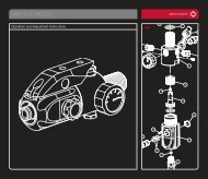
LPR<br />
(Low Pressure Regulator) -<br />
Adjustments and Maintenance<br />
ON/OFF VALVE - Maintenance and Changing O-rings<br />
5 5 5<br />
3<br />
9<br />
8<br />
7<br />
6<br />
4<br />
2<br />
1<br />
FIGURE 1<br />
WARNING<br />
When servicing your marker:<br />
• Make sure your hopper is removed<br />
from the <strong>DM6</strong>.<br />
• Make sure there are no paintballs in the<br />
breech of the <strong>DM6</strong>.<br />
• Always remove the air supply and<br />
relieve all gas pressure in the <strong>DM6</strong><br />
before disassembly.<br />
• It is not recommended for the user to<br />
remove the LPR from the body and<br />
disassemble it.<br />
LPR ASSEMBLY, CLEANING, TESTING AND CHANGING SEALS<br />
The Low-Pressure Regulator (LPR) is located in the lower back of the <strong>DM6</strong> (see figure 1). The function of the LPR is<br />
to lower the air pressure supplied to the marker by the in-line, before it reaches the solenoid. This pressure is used<br />
to move the bolt forward and back. The factory setting is 75 PSI. You can fine tune your <strong>DM6</strong> to its minimum cycle<br />
pressure. This will reduce the amount of force of the bolt hitting the ball (reducing ball breaks) and help with<br />
efficiency. Too low of pressure will cause the bolt to not cycle, move sluggishly or not at all. If you experience<br />
dramatic shoot down during rapid fire, the LPR may be adjusted too low. Too high of pressure will cause the marker<br />
not to shoot as smoothly, potentially increase ball breakage and cause undue wear and fatigue on the bolt<br />
components.<br />
It is important to keep the seat and piston face clean of all dirt and debris. Clean the seat and piston face and<br />
grease the retainer o-ring every six months or 60,000 shots.<br />
The LPR has five components and six seals<br />
1 Piston large o-ring (012 BN70) 6 Piston small o-ring (006 UR90)<br />
2 Piston 7 Main seal (mounted in the seal retainer)<br />
3 Piston spring 8 Seal retainer o-ring (010 BN70)<br />
4 Body 9 Seal retainer (functions as an adjustment screw also)<br />
5 Body o-rings (3pcs, 012 BN70)<br />
The only user-serviceable part in the LPR is the seal retainer. This seal needs to be changed in the unlikely case the LPR is creeping up.<br />
CHANGING THE SEAL RETAINER<br />
1 Screw out LPR back cover behind the marker using a 1/4” Allen wrench.<br />
2 Screw out LPR seal assembly (brass) using a 3/16” Allen wrench.<br />
3 Screw in new LPR seal assembly.<br />
4 Screw LPR back cover in place securely.<br />
If the user needs to replace the whole LPR assembly, follow these instructions:<br />
1 Take frame off the marker.<br />
2 Screw out LPR set screw using a 5/64” Allen wrench.<br />
3 Screw out LPR cap using a 1/4” Allen wrench.<br />
4 Pull out the LPR by screwing a rod with a 10/32 thread into the seal retainer (brass piece) inside the LPR and pulling it out.<br />
5 Put everything back in reverse order. Be sure to grease the #019 o-rings, so as to prevent cutting them<br />
upon installation.<br />
6 Tighten LPR back cover securely.<br />
The LPR pressure can be set quite accurately even without an LPR test tool. Screwing the adjustment screw (seal<br />
retainer) all the way in will set the LPR pressure to approximately 25 psi. Now turning out the adjusting screw 180<br />
degrees will increase the pressure by approximately 5 psi. For example, turning the screw 5 complete turns out will<br />
set the pressure to approximately 75 psi. Use a 3/16” Allen wrench to make all adjustments to the LPR. Turning the<br />
adjustment screw clockwise, or in, will lower the LPR’s output pressure. Turning the adjustment screw<br />
counterclockwise, or out, will raise the LPR’s output pressure.<br />
ON/OFF: USAGE AND CHANGING O-RINGS<br />
The On/Off knob is located under the barrel in the front of the <strong>DM6</strong> (see figure 2). Using the on/off is simple. To turn<br />
the gas off, turn the knob so that is is facing sideways. If you had gas inside the marker, it will bleed out. To turn the<br />
gas on, turn the knob so that it faces vertically.<br />
The ON/OFF has three o-rings<br />
1 009 UR90 2 009 BN70<br />
In case of a leak from the on/off, it is easy to service:<br />
1 Take the frame off the marker.<br />
2 Unscrew set screw holding on/off in place (screw just in front of the front frame screw).<br />
3 Pull out on/off, change damaged o-ring(s).<br />
4 Lube with grease.<br />
5 Push back in.<br />
6 Screw in set screw.<br />
7 Put frame back on.<br />
8 Gas up and test.<br />
MAINTENANCE<br />
The on/off needs very little maintenance. To help prevent o-ring failure and leaks, grease the on/off every four months<br />
or sooner, depending on the severity of playing conditions. Cold, wet weather will shorten the effective life of the<br />
grease. Heavy dust or fine sand can infiltrate the on/off and prevent it from moving smoothly and/or cut the o-rings.<br />
NOTE: Air may still be present in the LPR and solenoid after the air has been vented from the marker by the on/off. Be<br />
sure all air has been vented by discharging the marker in a safe direction. If servicing the marker, removal of the bolt<br />
will also allow any trapped air to escape.<br />
FIGURE 2<br />
WARNING<br />
When servicing your marker:<br />
• Make sure your hopper is removed<br />
from the <strong>DM6</strong>.<br />
• Make sure there are no paintballs in the<br />
breech of the <strong>DM6</strong>.<br />
• Always remove the air supply and<br />
relieve all gas pressure in the <strong>DM6</strong><br />
before disassembly.<br />
• It is not recommended for the user to<br />
remove the LPR from the body and<br />
disassemble it.<br />
10 11
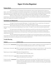
HYPER2 REGULATOR - ADJUSTMENTS AND MAINTENANCE<br />
ANTI CHOP EYES- Maintenance and Changing<br />
1<br />
USAGE<br />
2<br />
Carefully connect your air hose from your bottle or air system to the Hyper 2 In-Line. The Hyper 2 In-Line is set by<br />
the factory to approximately 145psi. This pressure should give you a velocity of approximately 285fps.<br />
ADJUSTMENTS<br />
3<br />
4<br />
5<br />
6<br />
7<br />
7<br />
The output pressure of the Hyper 2 In-Line is adjusted by turning the brass seat housing. The seat housing screw is<br />
located up inside the bottom of the reg. A 3/16” Allen wrench will be needed for this operation. By turning the<br />
housing counterclockwise, you will increase the output pressure of the regulator to the marker. By turning the<br />
housing clockwise, you will decrease the output pressure of the regulator.<br />
8<br />
9<br />
10<br />
11 13<br />
12<br />
14<br />
ANTI CHOP EYES<br />
The Anti Chop Eye (ACE) system will prevent the <strong>DM6</strong> from chopping paint by not allowing the<br />
marker to fire until a ball is fully seated in front of the bolt. The eyes use a beam across the<br />
breech. On one side there is a transmitter, and on the opposite side a receiver. In order for the<br />
marker to fire with the eyes turned on, the signal between the two eyes must be broken. After<br />
every shot, before the next ball drops in the breech, the eye transmitter and receiver must see<br />
each other. If there is a malfunction the LED's on the board will start blinking green. This means<br />
that the receiver and the emitter do not see each other. If this is the case, there are normally<br />
two reasons, either there is dirt, paint or grease blocking the beam, or the battery is so low<br />
there is not enough power to create a strong enough beam.<br />
NOTE: If the battery is low, the marker may act as if the eyes are dirty or not fire at all. In this<br />
case, replace the battery.<br />
FIGURE 2<br />
FIGURE 1<br />
WARNING<br />
• The Hyper 2 can hold a small residual<br />
charge of gas, typically 2 shots. Always<br />
discharge the marker in a safe direction to<br />
relieve this residual gas pressure.<br />
• Always remove the regulator from the<br />
<strong>DM6</strong> before servicing.<br />
• Improper stacking of shims will cause<br />
failure of the regulator and possible<br />
damage to the <strong>DM6</strong>.<br />
• Excessive dirt and debris can affect<br />
the Hyper 2 ’s performance and increase<br />
the need for servicing.<br />
After each adjustment of the output pressure of the Hyper 2 In-Line, you will need to cycle your marker a few<br />
times. This will allow your marker and air system to stabilize at their new operating pressure. The Hyper 2 will need<br />
a break-in period of about 2,500 shots to let its seat form to the piston and reach its optimum performance.<br />
The Hyper 2 has eight components and six o-rings<br />
1 Retaining cap 6 Piston small o-ring (007 UR90) 11 Piston large o-ring (018 BN70)<br />
2 Swivel 7 Swivel o-rings (013 BN70) 12 Reg cap o-ring (020 BN70)<br />
3 Seat housing 8 Reg body 13 Reg cap<br />
4 Retainer o-ring (010 BN70) 9 Shim stack 14 ASA o-ring (015 BN70)<br />
5 Reg seat 10 Piston<br />
Disassembly of the Hyper 2 In-Line is easily done with 3/8”<br />
and 5/16” Allen wrenches.<br />
MAINTENANCE<br />
Shim Stack<br />
Figure 2<br />
To ensure top performance from the Hyper 2 , maintenance should be performed every six months or sooner,<br />
depending on the severity of playing conditions. Cold, wet weather will shorten the effective life of the grease.<br />
Heavy dust or fine sand can infiltrate the Hyper 2 and prevent the piston from moving smoothly and/or cut the<br />
o-rings.<br />
1 Make sure the inlet and outlet ports and connecting fittings are free of all dirt and paint.<br />
2 Examine all o-rings for nicks or cuts.<br />
3 Carefully inspect the seat for excessive wear that might cause spiking and over-pressurizing.<br />
4 Clean any accumulated dirt out of the air chambers and passages.<br />
5 Keep the piston o-rings and spring pack generously greased to allow smooth velocity adjustment and prevent<br />
erratic velocity spikes and drop off.<br />
6 Clean off all old grease that may be contaminated with dirt; reapply fresh grease to the piston and other<br />
necessary areas.<br />
7 Be sure to reassemble the internal components and shim stack (see figure 2) in the proper order and direction.<br />
8 See diagram for assistance.<br />
SELF CLEANING EYE FEATURE<br />
The <strong>DM6</strong> is equipped with a self cleaning eye feature. There are two clear acrylic pieces mounted inside the breach of the gun<br />
covering the eyes (see figure 3). When the bolt tip O-ring passes these acrylic pieces, it sweeps off any dirt, grease or paint<br />
that could be blocking the eyes. Normally it is enough to just fire the <strong>DM6</strong> to clean anything blocking the eyes. If this does not<br />
clean up the blockage, use a swab to clean up the breach. For a more through clean up, remove the eye plates. To remove the<br />
eye covers, you will need a 1/16” Allen wrench. Simply insert the allen wrench into the hole in the eye cover to access the<br />
retaining screw (see figure 2). As you back the screw out, the plate will be pushed up. Next, pull out the actual eye<br />
receiver/emitter from the self cleaning eye piece (avoid pulling the wires) and finally pull out the self cleaning eye piece with a<br />
pair of needle nose pliers (see figure 3). Avoid scratching the surface of the eye piece that sits inside the breach.<br />
Take care not to lose the ball detent spring while removing the eye plate.<br />
NOTE: Regular eye cleaning is recommended even if no paint is broken. Clean the eyes every two months or 10,000 shots to<br />
eliminate any built up dirt. Excess grease from the front bolt o-ring can build up in front of the eyes. Remember to check for<br />
this after greasing the bolt and cycling the marker a few times.<br />
CHANGING BALL DETENTS<br />
The ball detent system is also located under the eye covers. The ball detent system needs little or no maintenance. There<br />
is a spring behind each detent, which holds the detent forward. This spring pressure should be easily overcome with very<br />
little force, such as a paintball moving past. If you are experiencing double feeding or chopping, check the condition of<br />
your ball detents with your finger to make sure they are not stuck in the up or down position and that they move in and<br />
out of the breech freely. If excessive broken paint or dirt has jammed your ball detents, remove the eye plates (being<br />
careful not to lose the detent springs) and pull the detents out for a thorough cleaning (see figure 4). Reinstall the detents,<br />
springs and eye covers after you have sufficiently cleaned the detents and breech.<br />
12 13<br />
FIGURE 3<br />
FIGURE 4<br />
1<br />
1<br />
NOTE: TAKE CARE WHEN REPLACING THE EYE COVERS. OVER-TIGHTENING THE RETAINING SCREW<br />
COULD RESULT IN STRIPPING THE THREADS.
ULTRALITE FRAME<br />
FIGURE 1<br />
WARNING<br />
• Be sure the trigger is not adjusted to the<br />
point where it is too sensitive and may<br />
cause accidental discharge of the marker.<br />
• Removing the trigger spring will cause<br />
premature wear on the microswitch,<br />
resulting in failure.<br />
• Be sure you do not pinch the wires<br />
between the frame and body if<br />
reattaching the frame to the body.<br />
2<br />
1<br />
ADJUSTING YOUR TRIGGER<br />
The trigger’s forward travel, over travel and spring tension are fully adjustable so that the user can fine-tune the<br />
trigger to his or her exact liking. You do not need to remove the frame from the gun in order to adjust the trigger<br />
pull.<br />
• There are two adjustment screws located on the right side of the Ultralite frame (see figure 1) and one<br />
adjustment screw behind the trigger. The two screws on the side of the frame adjust the travel of the trigger.<br />
The one located behind the trigger is used to change the tension of the trigger spring.<br />
TO ADJUST TRIGGER TRAVEL<br />
• Use a 5/64” Allen wrench to make the desired adjustments.<br />
• The screw toward the front of the trigger (#1 in figure 1) controls the forward travel. Screwing it in will<br />
shorten the trigger’s length of pull.<br />
Note: If this screw is adjusted too far, the switch will be held down at all times and the marker will not fire.<br />
• The screw toward the rear of the trigger (#2 in figure 1) controls the over travel. By turning this screw you<br />
can adjust how far the trigger will travel after it reaches the firing point.<br />
Note: If this screw is adjusted too far, the trigger will not be allowed to travel far enough to depress the<br />
switch and fire the marker.<br />
TO ADJUST SPRING TENSION<br />
• Use a 5/64” Allen wrench to make the desired adjustment. The adjustment is made by pushing the allen key<br />
through a hole in the trigger.<br />
• To make the trigger pull stiffer, turn the allen key clockwise or in.<br />
• To make the trigger pull lighter, turn the allen key counterclockwise or out.<br />
INTEGRATED LOCKING DOVETAIL FEATURE<br />
The UltraLite frame comes equipped with an integrated locking dovetail. There is a locking screw located on the<br />
bottom right side of the UltraLite frame. It can be accessed with a 1/8" allen key through a hole in the grips panels.<br />
To unlock a part attached to the dovetail of the frame, turn the locking screw counter clockwise one full turn and<br />
slide part off the rail. To attach a part to the rail, slide the part on and turn the locking screw clockwise until part is<br />
firmly locked in place.<br />
REMOVING ULTRALITE FRAME FROM THE <strong>DM6</strong><br />
If there is ever need to remove the Ultralite frame from the <strong>DM6</strong> make sure to follow these steps.<br />
• Remove three grip panel screws with a 3/32" allen wrench from the right side of UltraLite frame<br />
• Disconnect the solenoid wire and the eye wire from their sockets by gently pulling them out<br />
• Using a 3/32" allen key, turn the front frame screw counterclockwise one full turn<br />
• Finally, turn out the back frame screw and slide the frame back and down until it comes off the <strong>DM6</strong><br />
To connect the frame follow above steps in reverse order.<br />
NOTE: BE SURE THAT THE FRAME AND TRIGGER ASSEMBLY ARE KEPT CLEAN. IF THERE IS EXCESS DIRT OR<br />
PAINT BUILD UP AROUND THE TRIGGER, THE TRIGGER WILL NO LONGER MOVE FREELY. IN ADDITION, PAINT<br />
AND DIRT CAN CAUSE THE MICROSWITCH TO NOT FUNCTION PROPERLY OR FAIL. BE SURE YOU DO NOT PINCH<br />
THE WIRES BETWEEN THE FRAME AND THE BODY WHEN REATTACHING THE FRAME AND BODY.<br />
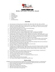
PARTS<br />
1 Adjustable Feed Neck<br />
2 On/Off Knob<br />
3 Ball Detent<br />
4 Eye Cover<br />
5 Self Cleaning Eye Lens<br />
6 Hyper 2<br />
7 On/Off Retaining Screw<br />
8 “ACE” Eye<br />
9 Solenoid<br />
10 Front Frame Screw<br />
11 Ultralite 45 Frame<br />
12 Rear Frame Screw<br />
13 LPR Retaining Screw<br />
14 LPR<br />
15 LPR Cap<br />
16 Fuse Bolt<br />
17 <strong>DM6</strong> Body<br />
14 15<br />
2<br />
4<br />
3<br />
6<br />
1<br />
7<br />
10<br />
5<br />
9<br />
8 13<br />
11<br />
7<br />
17<br />
12<br />
16<br />
14<br />
15<br />
LIST
TROUBLE SHOOTING GUIDE<br />
<strong>DM6</strong> TROUBLE SHOOTING<br />
AIR LEAK BETWEEN THE FRAME AND BODY<br />
- First remove the frame and try to pinpoint the source of the leak:<br />
- If it comes from the small hole under the LPR, you need to remove your LPR.<br />
The cause of the leak is either one of the #015 o-rings on the outside of the LPR or the<br />
#006 o-ring found inside the LPR (see page 10).<br />
- If it comes from somewhere around the solenoid, the first thing to do is to turn the<br />
on/off knob to the off position. If the leak continues, the cause is a bad o-ring on the<br />
on/off. If it stops there are three likely causes:<br />
1. #015 on the bolt sail<br />
2. #020 on the cylinder (the one on the middle of the cylinder)<br />
3. Seat under the solenoid<br />
AIR LEAK FROM THE BACK OF THE LPR PLUG<br />
- Remove the LPR and change the back-most #015 o-ring on the LPR body. If that does<br />
not help, change the seal retainer inside the LPR body. Refer to page 10 of the manual<br />
for disassembly instructions.<br />
INCONSISTENT VELOCITY OVER THE CHRONO<br />
- In-line regulator not giving consistent pressure: refer to the Hyper2 manual for service,<br />
or if using an after-market regulator, refer to its manufacturer.<br />
- Low battery: change the battery.<br />
- Bad seals in the bolt: take out the bolt, clean it, lube it with <strong>Dye</strong> Slick Lube. Replace<br />
any o-rings that seem damaged, swollen or in otherwise bad shape. Most likely the<br />
o-ring at fault is the #017 front wall o-ring. Also check that the #014 o-ring on the bolt<br />
tip is in place.<br />
- LPR pressure set incorrectly or LPR pressure fluctuating: if pressure is too low, the bolt<br />
will not cycle correctly. Try turning the LPR pressure a bit higher. If the pressure seems<br />
inconsistent, you can have an authorized <strong>DM6</strong> center check the LPR pressure. List of<br />
tech centers can be found at www.dyematrix.com.<br />
- Dwell set too low: if you set the dwell too low, the dump chamber will not empty<br />
completely and will cause erratic velocities. Refer to board settings page for<br />
information on setting the dwell.<br />
MARKER SHOOTING SLOW WHEN EYE IS ON AND BLINKING GREEN<br />
- The eyes are not working correctly. Clean the eyes. You'll know that they are clean if the<br />
LED turns red when there is nothing inside the breech of the <strong>DM6</strong>.<br />
- Make sure the eye wires are not broken or pinched.<br />
- The battery may be low. In this case, the battery should be changed as soon as possible.<br />
MARKER ISN'T WORKING THOUGH EYES ARE CLEAN AND ALL WIRES ARE CONNECTED;<br />
MARKER DOES WORK IF EYES ARE TURNED OFF<br />
- Change the battery. The voltage in the battery is too low for the eye to<br />
function correctly.<br />
MARKER WILL NOT TURN ON OR OFF; CONTINUOUSLY CYCLES THROUGH BOOT-UP; EYES WILL<br />
NOT TURN ON OR OFF<br />
- The button pad may need replacement.<br />
AIR LEAK THROUGH THE BARREL<br />
- There are three possible o-rings that cause this leak:<br />
- If the leak comes through the inside of the bolt, replace the #013 on the bolt top hat.<br />
If the cause is this #013 o-ring, the input pressure to the gun is likely too high.<br />
- If it’s leaking from the outside of the bolt shaft, the bad o-ring is either the #017 on the<br />
inside of the bolt cylinder or the #020 on the outside of the bolt can.<br />
AIR LEAK FROM THE BACK HOLE OF THE BOLT<br />
- Take out the bolt, unscrew the back part of the bolt and change the #009 o-ring on the<br />
back of the bolt shaft.<br />
HYPER2 TROUBLE SHOOTING (REFER TO PAGE 12)<br />
NOTE: TO TAKE APART THE REGULATOR, USE A 5/16” ALLEN WRENCH ON THE BOTTOM AND A 3/8” ALLEN<br />
WRENCH ON THE TOP. TWIST COUNTERCLOCKWISE TO OPEN. DO NOT USE ANY OTHER METHOD.<br />
NO OR POOR AIR FLOW<br />
- Check for blocked air passage in hose line or regulator.<br />
- Adjustment screw may be screwed in too far.<br />
- Seat may have excessively deep piston groove cut into it. Replace if needed.<br />
WARRANTY<br />
DYE Precision, Inc.<br />
Warrants for one year to the initial retail purchaser, from the initial date of purchase, that the paintball marker and regulator are free from defects in materials and<br />
workmanship, subject to the requirements, disclaimers and limitations of this warranty. Disposable parts, normal maintenance and standard wear and tear parts such as<br />
batteries, o-rings and seals are not warrantied. The solenoid and electronic components on the marker are warrantied for six months. This warranty does not cover scratches,<br />
nicks, improper disassembly, improper re-assembly, misuse, neglect or improper storage. Modification to the product will void the warranty. The only authorized lubricant for<br />
the marker is Slick Lube. Use of any other lubricant will void your warranty. This warranty is limited to repair or replacement of defective parts with the customer to pay<br />
shipping costs. Warranty card and proof of purchase must be submitted to <strong>Dye</strong> Precision for warranty to be in effect. This warranty is not transferable. This warranty does not<br />
cover performance. Paintball markers are non-refundable.<br />
TECHNICAL SUPPORT<br />
Our Technical Support Department is open Monday through Friday, from 9am to 5pm, PST, and can be reached at 858-536-5183. Additional support is available through our<br />
web site, www.dyepaintball.com.<br />
DISCLAIMER<br />
The specifications & photographs in this material are for information and general guidance purposes only.<br />
Our products are continually updated and changes may be made to specification, design or appearance from time to time. These are subject to change without notice.<br />
Contents of box may therefore vary from owner’s manual. For details of changes in design, specification or appearance consult your local distributor or dealer.<br />
The FUSE bolt, Hyper 2 and Slick Lube are registered trademarks. Design rights, copyrights and all other rights reserved. All patterns, drawings, photographs, instructions<br />
or manuals remain the intellectual property of the manufacturer.<br />
Covered by U.S. Patent 5,613,483. Additional patents pending.<br />
All rights will be strictly enforced.<br />
TRIGGER BOUNCE<br />
- If you are having excessive trigger bounce when firing the gun, make sure you have an<br />
uncut spring behind the trigger. Adjust the trigger so that the firing point of the trigger<br />
pull is located about halfway through the travel of the pull.<br />
Raise the trigger sensitivity value.<br />
AIR LEAK BETWEEN THE BODY AND REAR CAP<br />
- Replace the #020 o-ring on the bolt rear cap.<br />
MARKER WILL NOT FIRE<br />
- A low battery may cause malfunctions to the marker. In this case, the battery should be<br />
changed as soon as possible.<br />
- Check to make sure the on/off is in the on position.<br />
- If the LED light is red, the marker will not fire because there is no ball in the breech.<br />
Hold the trigger for 1 second and the marker should fire. If it does not fire after holding<br />
the trigger, or if the LED light is green and it will not fire:<br />
- Make sure dwell setting is at stock value.<br />
- Make sure the trigger is adjusted properly and is actuating the microswitch.<br />
- Make sure there are no broken solenoid wires.<br />
- Sticking bolt: pull out bolt and re-grease o-rings.<br />
ERRATIC VELOCITY OR SHOOT DOWN<br />
- Piston or shim stack may be binding due to excessive dirt or lack of lubricant.<br />
- Seat may be dirty or damaged. Clean and grease regulator. Inspect and replace<br />
damaged parts as needed.<br />
- Make sure shim stack is stacked properly.<br />
OUTPUT PRESSURE CREEPS UP<br />
- Dirty seat or damaged piston face. Clean and inspect; if either is damaged, replace.<br />
- Piston o-ring #007 UR90 may be damaged.<br />
AIR LEAK FROM SIDE VENT HOLE<br />
- Piston o-rings #007 UR90 and #018 BN70 may be damaged. Inspect o-rings. Replace if any<br />
visible nicks or cuts are found.<br />
AIR LEAK FROM BOTTOM OF ADJUSTMENT SCREW<br />
- This is a safety bleed-off to help prevent over-pressurizing. De-gas the Hyper2; be sure all<br />
air is vented out of the regulator. Supply air back to the regulator. The leak should stop. If the leak<br />
persists, replace the regulator seat. Make sure there are no nicks or scratches on the raised ring at<br />
the bottom of the seat-retaining cavity.<br />
DYE Precision, Inc.<br />
USA 10637 Scripps Summit Ct. San Diego, CA 92131<br />
P 858-536-5183 F 858-536-5191<br />
EUROPE Unit 1, ZK Park, 23 Commerce Way<br />
Croydon, Surrey CRO 4ZS United Kingdom<br />
P +44 (0) 20-8649-6330 F +44 (0) 20-8649-6339<br />
ASIA 3F-2, No. 287, Jung Jeng Rd., Luju Hsiang<br />
Taoyuan 338, Taiwan (R.O.C.)<br />
P +886-3-312-6540 F +886-3-311-8723<br />
16 17