9 Pin RS-232 to Current Loop Converter - Wantronix
9 Pin RS-232 to Current Loop Converter - Wantronix
9 Pin RS-232 to Current Loop Converter - Wantronix

Create successful ePaper yourself
Turn your PDF publications into a flip-book with our unique Google optimized e-Paper software.
<strong>232</strong>CL9R0900 – pg. 1/2<br />
9 <strong>Pin</strong> <strong>RS</strong>-<strong>232</strong> <strong>to</strong> <strong>Current</strong> <strong>Loop</strong> <strong>Converter</strong><br />
Model <strong>232</strong>CL9R<br />
The Model <strong>232</strong>CL9R is a passive 9 pin <strong>RS</strong>-<strong>232</strong> <strong>to</strong> current loop converter.<br />
This converter requires a 12VDC-power supply at 100mA. Additional resis<strong>to</strong>rs are<br />
supply for an active source.<br />
Figure 1.<br />
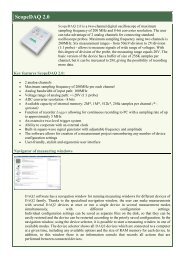
To connect the converter <strong>to</strong> an existing current loop port, you must first determine if the port is active or passive.<br />
For a port <strong>to</strong> be active, it must have an internal power supply which provides the 20mA current for the transmitter,<br />
receiver, or for both. This information should be available in the instruction manual. If the instruction manual is not<br />
available the simplest way <strong>to</strong> determine this is <strong>to</strong> break the loop (disconnect it) and see if there is any DC voltage across<br />
the output or input pairs.<br />
<strong>Current</strong> loop interfaces normally consist of four wires. They are usually labeled T+, T-, R+, and R-. T+ and T- are<br />
the transmit plus and transmit minus lines and data is output from that device on those lines. The R+ and R- lines are the<br />
receive plus and receive minus lines and data is input in<strong>to</strong> that device on these lines.<br />
Interconnection of the two current loop devices is different depending on whether your unit is active or passive.<br />
Connection <strong>to</strong> an active current loop port is very simple. Your unit’s T+ and T- lines go <strong>to</strong> the B&B unit’s R+ and R- lines,<br />
and your unit’s R+ and R- lines go <strong>to</strong> the B&B unit’s T+ and T- lines, as shown in figure 2.<br />
© B&B Electronics - January 2000<br />
This product designed and manufactured in USA of domestic and imported parts by
<strong>232</strong>CL9R0900 – pg. 2/2<br />
Note: The R+ & R- indentification doesn't imply a<br />
direct connection across the receiver.<br />
<strong>RS</strong>-<strong>232</strong><br />
<strong>to</strong><br />
<strong>Current</strong><br />
<strong>Loop</strong><br />
<strong>Converter</strong><br />
T+<br />
T-<br />
R+<br />
R-<br />
R+<br />
R-<br />
T+<br />
T-<br />
Vs<br />
Vs<br />
Active <strong>Current</strong><br />
<strong>Loop</strong> Port<br />
Note: The T+ & T- indentification doesn't imply a<br />
direct connection across the transmitter.<br />
Figure 2. Connection <strong>to</strong> an Active <strong>Current</strong> <strong>Loop</strong><br />
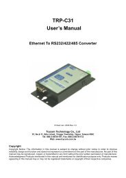
Connection <strong>to</strong> a passive current loop port requires a 12 VDC power supply. Use the 470 ohm resis<strong>to</strong>rs inside of<br />
our converter <strong>to</strong> create a 20 ma current source, as shown in figure 3.<br />
<strong>RS</strong><strong>232</strong> TO CURRENT<br />
LOOP CONVERTER<br />
T+ 14<br />
PASSIVE CURRENT<br />
LOOP CONVERTER<br />
R+<br />
T-<br />
19<br />
6<br />
R-<br />
470<br />
9<br />
21<br />
+12VDC<br />
470<br />
22<br />
R+<br />
25<br />
R-<br />
23<br />
T+<br />
T-<br />
YOUR<br />
EQUIPMENT<br />
Figure 3. Connection <strong>to</strong> a Passive <strong>Current</strong> <strong>Loop</strong><br />
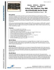
Interconnection of two B&B current loop converters also requires the use of a 12 VDC power supply since they<br />
are both passive ports. See figure 4.<br />
T+ 14<br />
14 T+<br />
T-<br />
19<br />
19<br />
T-<br />
6<br />
6<br />
470<br />
9<br />
+12VDC<br />
21<br />
9<br />
21<br />
470<br />
470<br />
22<br />
22<br />
470<br />
R+<br />
25<br />
25<br />
R+<br />
R- 23<br />
23<br />
R-<br />
Figure 4. Interconnection of Two <strong>Current</strong> <strong>Loop</strong> converters<br />
© B&B Electronics - January 2000<br />
This product designed and manufactured in USA of domestic and imported parts by