
Create successful ePaper yourself
Turn your PDF publications into a flip-book with our unique Google optimized e-Paper software.
Engineering & Expertise<br />
Designing pump sumps<br />
FormED <strong>suction</strong> intakE
EnginEEring & ExpErTisE<br />
Total solution engineering<br />
increases operational efficiency<br />
2<br />
introduction<br />
The primary function of a propeller pump<br />
<strong>intake</strong> is to provide stable, even and rotation<br />
free flow to the pump. A good <strong>intake</strong><br />
design will enable optimum pump performance<br />
under all operating conditions.<br />
Good <strong>intake</strong> design eliminates hydraulic<br />
phenomena and other conditions, such as<br />
sedimentation and accumulation of floating<br />
debris, that can have a negative impact on<br />
pump performance. In addition, the sump<br />
should be as compact and straightforward<br />
in design to reduce the installation footprint<br />
and minimize construction costs.<br />
Determining the optimal pump <strong>intake</strong> therefore<br />
requires engineering and expertise. We<br />
will present guidance for the design of pump<br />
<strong>intake</strong>s for propeller pumps. Methods and procedures<br />
are given for handling various inflow<br />
conditions, preventing solids buildup and<br />
using specially developed formed <strong>suction</strong> <strong>intake</strong>s<br />
in order to achieve an efficient, compact<br />
propeller sump design in very limited space.<br />
Theoretical analysis<br />
Products<br />
Physical tests<br />
Reference installations<br />
Engineering & Expertise<br />
Achieving lowest total cost of ownership<br />
When providing pumping solutions, <strong>Flygt</strong> prefers to<br />
take the total cost of ownership into consideration.<br />
Unplanned<br />
Investment<br />
Operational<br />
� Investment costs<br />
Costs associated with design, excavation, civil work,<br />
product purchases, installation and commissioning.<br />
� Operational costs<br />
Over time, energy usage and maintenance costs<br />
are often the major contributors to the overall costs<br />
along with the cost of labor required to run the<br />
system.<br />
� Unplanned costs<br />
When things go wrong, such as pump failures stemming<br />
from problematic station design, costs can<br />
sky rocket. Unexpected downtime can cause sewer<br />
backups, overflows, basement flooding and untreated<br />
effluent. On top of that, you have to repair<br />
pumps and take corrective measures regarding the<br />
station design.<br />
Engineering & Expertise<br />
Thanks to our engineering expertise, we can lower<br />
your total cost of ownership. We can analyze your<br />
system using state-of-the-art computational programs.<br />
We can test your pump station using scale<br />
models if required. We can also provide you with<br />
reference installations that are similar to your project.<br />
All of this together with our premium products<br />
provides you with an optimized design.
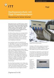
Minimizing station<br />
footprint<br />
The <strong>Flygt</strong> <strong>Formed</strong> <strong>suction</strong> <strong>intake</strong> device (Fsi) is an<br />
inlet device that provides optimal inflow to the propeller<br />
pump by gradually accelerating and redirecting<br />
the flow towards the pump inlet. its primary function<br />
is to condition the incoming flow into a uniform<br />
profile and redirect the flow.<br />
The <strong>Flygt</strong> <strong>Formed</strong> <strong>suction</strong> <strong>intake</strong> device is ideal for<br />
use:<br />
• When adverse inflow conditions exist<br />
• When space available for the pump station is<br />
limited<br />
• For <strong>intake</strong>s with perpendicular or skewed inflows<br />
• For critical installations and continuous operation<br />
By providing a reliable pump <strong>intake</strong> in limited<br />
space, the <strong>Flygt</strong> <strong>Formed</strong> <strong>suction</strong> <strong>intake</strong> device is<br />
able to achieve a more economical pump station<br />
solution with a smaller footprint and better hydraulic<br />
performance than with standard inlet devices.<br />
inTrODUCTiOn<br />
Achieving lowest total cost of ownership<br />
The <strong>Flygt</strong> <strong>Formed</strong> <strong>suction</strong> <strong>intake</strong> device is designed<br />
to reduce overall investment costs by reducing<br />
the propeller pump station footprint to an absolute<br />
minimum. This pump <strong>intake</strong> device ensures<br />
highly reliable operation and therefore lowers the<br />
risk of downtime. it combines the ease of fabrication<br />
with relatively small dimensions to deliver optimal<br />
hydraulic performance, which contributes to<br />
equipment longevity and the lowest total cost of<br />
ownership.<br />
3
DEsign COnDiTiOns<br />
Adverse hydraulic<br />
phenomena<br />
According to the Hydraulic Institute: “Ideally, the<br />
flow of water into any pump should be uniform,<br />
steady and free from swirl and entrained air. Lack<br />
of uniformity can cause the pump to operate away<br />
from the optimum design condition, and at a<br />
lower hydraulic efficiency. Unsteady flow causes<br />
the load on the impeller to fluctuate, which can<br />
lead to noise, vibration, bearing problems and fatigue<br />
failures of pump shafts.”<br />
To ensure the expected pump performance and<br />
long service intervals, it is important to design the<br />
pump sump to prevent adverse flow conditions.<br />
Excessive pre-swirl<br />
pre-swirl changes the flow conditions at the pump<br />
inlet, which results in a change in the relative impeller<br />
speed. This, in turn, causes a change in pump<br />
performance, which can lead to overloading the<br />
motor or reduced pump performance. Excessive<br />
pre-swirl can also result in bearing wear and cavitation<br />
across the impeller area. pre-swirl usually<br />
originates from an asymmetric velocity distribution<br />
in the approach channel, which evolves into a<br />
pre-swirl at the pump inlet. The Hydraulic institute<br />
recommends a pre-swirl angle that does not exceed<br />
5°, calculated from the ratio between the tangential<br />
velocity and the axial velocity.<br />
A non-uniform approach inflow leads to pre-swirl, which can<br />
overload the motor or reduce pump performance.<br />
4<br />
Uneven velocity distribution at the pump <strong>intake</strong><br />
Uneven velocity distribution can result from different<br />
types of phenomena and disturbances. While<br />
some unevenness in velocity distribution is inevitable<br />
and does not harm the pump, variations that<br />
are greater than 10% at the pump <strong>intake</strong> can have<br />
severe consequences and should be avoided. A<br />
large variation results in an uneven load on the impeller<br />
and bearings. Unsteady flow causes the load<br />
on the impeller to fluctuate, which leads to noise, vibration,<br />
bearing loads and increased risk of fatigue<br />
failures.<br />
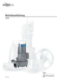
CFD simulation of the flow distribution at the impeller plane.<br />
Uneven velocity into the pump inlet leads to noise, vibration<br />
and bearing wear.
Entrained air<br />
it is widely known that even minor air entrainment,<br />
of some 3.4% of the volume, will lead to a clear<br />
reduction in pump performance and loss of efficiency;<br />
the severity depends upon the quantity of<br />
air entrained and the pump type. The expansion of<br />
ingested air bubbles within the impeller may result<br />
in mechanical imbalance, vibration and acceleration<br />
of mechanical wear. normal design practices<br />
recommend the exclusion of any air entrainment in<br />
the approach flow to the pump <strong>intake</strong>. in addition,<br />
entrained air leads to increased corrosion.<br />
While air bubbles may be present in the liquid for a<br />
variety of reasons, their presence is usually due to<br />
cascading of the water as it enters the sump from<br />
a weir, culvert or incoming pipe located above the<br />
surface water level in the sump.<br />
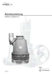
Entrained air and vortex shown in scale model test.<br />
Entrained air can cause reduction in discharge and loss of<br />
efficiency.<br />
Vortices<br />
Unlike excessive pre-swirl, vortices appear locally<br />
with higher intensity and are a major hindrance<br />
to proper pump operation, resulting in cavitation,<br />
uneven load, noise and vibration. There are several<br />
different types of vortices.<br />
The most commonly known type is the free surface<br />
vortex, which can have varying degrees of intensity<br />
– from weak surface vortices to fully developed vortices<br />
with a continuous air core that extends from<br />
the surface into the pump.<br />
Less well known, but just as common is the vortex<br />
that originates under the surface from the sump<br />
bottom, walls or between two pumps, and extends<br />
to the pump inlet. This type of vortex can achieve<br />
high rotational speeds with high subpressures and<br />
cavitations.<br />
strong surface vortex with an air core will result in cavitation,<br />
uneven load, noise and vibration.<br />
strong submerged vortex.<br />
5
pUMp sTATiOn DEsign<br />
Achieving uniform<br />
inflow<br />
pump station with open channels to the pumps.<br />
schematic plan of a pump station with open channels to the<br />
pumps.<br />
6<br />
To achieve satisfactory homogeneous flow into the<br />
propeller pump, there are two major types of pump<br />
station designs: the open sump <strong>intake</strong> and the<br />
formed <strong>suction</strong> <strong>intake</strong>.<br />
Open sump <strong>intake</strong> design<br />
The most commonly used approach is the open<br />
sump <strong>intake</strong> design with open channels into the<br />
pumps. This design is the most sensitive to nonuniform<br />
approach flows; therefore, it requires the<br />
use of a longer forebay and longer dividing walls<br />
between the individual pump bays than the formed<br />
<strong>suction</strong> <strong>intake</strong> design.<br />
To achieve a steady, uniform flow towards each<br />
pump, the flow into the pump should be parallel to<br />
the pump channel. ideally, the inlet to the sump is<br />
placed directly opposite the pumps and is directed<br />
towards these, but in many cases this is not possible<br />
due to angled inflow or lack of space.<br />
Open sump <strong>intake</strong> design includes devices such as<br />
splitters and divider plates that alleviate the effects<br />
of minor asymmetries in the approach flow.<br />
Cross-section of a pump station with open channels to the<br />
pumps.
<strong>Formed</strong> <strong>suction</strong> <strong>intake</strong> design<br />
in situations with adverse flow conditions or limited<br />
space, the use of a formed <strong>suction</strong> <strong>intake</strong><br />
design may be more appropriate. its main function<br />
is to normalize the flow by means of acceleration<br />
and redirect the flow vertically into the pump inlet.<br />
The formed <strong>suction</strong> <strong>intake</strong> design can be constructed<br />
either of concrete or steel. The <strong>intake</strong><br />
reduces disturbances and swirl in the approach<br />
flow. The inclined front wall is designed to prevent<br />
stagnation of the surface flow. The geometrical<br />
features of this <strong>intake</strong> provide smooth acceleration<br />
and smooth turns as the flow enters the pump. This<br />
design is recommended for stations with multiple<br />
pumps with various operating conditions.<br />
<strong>Formed</strong> <strong>suction</strong> <strong>intake</strong> design is the least sensitive<br />
to disturbances in the approach flow that can<br />
result from:<br />
• Diverging flow<br />
• Flow that must be redirected in the forebay<br />
• Single pump operation at partial load<br />
pump station with formed <strong>suction</strong> <strong>intake</strong> in concrete.<br />
schematic plan of a formed <strong>suction</strong> <strong>intake</strong> with side inlet. Cross-section of a formed <strong>suction</strong> <strong>intake</strong>.<br />
7
FLygT FOrMED sUCTiOn inTAkE<br />
Optimal inflow with minimal<br />
sump footprint<br />
The <strong>Flygt</strong> <strong>Formed</strong> <strong>suction</strong> <strong>intake</strong> device.<br />
Comparison of the size of different station designs with a side inlet.<br />
Comparison of the size of different station designs with a front inlet.<br />
8<br />
100%<br />
<strong>Formed</strong> <strong>suction</strong> <strong>intake</strong> design<br />
100%<br />
100%<br />
~80%<br />
~85%<br />
<strong>Flygt</strong> Fsi<br />
100% 100%<br />
100%<br />
An alternative to a formed <strong>suction</strong> <strong>intake</strong> design is<br />
the <strong>Flygt</strong> <strong>Formed</strong> <strong>suction</strong> <strong>intake</strong> device, a specially<br />
engineered device for propeller pump <strong>intake</strong>s.<br />
With the <strong>Flygt</strong> <strong>Formed</strong> <strong>suction</strong> <strong>intake</strong> device, it is<br />
possible to design an even more compact station.<br />
Compared to the already compact <strong>Flygt</strong> standard<br />
open sump <strong>intake</strong> design, the <strong>Flygt</strong> <strong>Formed</strong> <strong>suction</strong><br />
<strong>intake</strong> device helps reduce the footprint of the sump<br />
by up to 60 percent. The <strong>Flygt</strong> <strong>Formed</strong> <strong>suction</strong><br />
<strong>intake</strong> device is capable of normalizing even higher<br />
flows than those handled by a formed <strong>suction</strong> <strong>intake</strong><br />
design.<br />
~85%<br />
Open sump <strong>intake</strong> design <strong>Formed</strong> <strong>suction</strong> <strong>intake</strong> design<br />
<strong>Flygt</strong> Fsi<br />
~80%
Design<br />
The <strong>Flygt</strong> <strong>Formed</strong> <strong>suction</strong> <strong>intake</strong> device is comprised<br />
of two sections.<br />
Diffuser<br />
The geometry of the diffuser, or transition section,<br />
is straightforward and easy to fabricate. it consists<br />
of two parallel walls, a horizontal bottom and an<br />
angled top. The inlet is equipped with chamfers,<br />
which dramatically reduce the flow separation into<br />
the inlet at lateral flow. if pre-swirl is high, a flow<br />
directing vane may be added between the diffuser<br />
and the bend.<br />
Bend<br />
The purpose of the bend, or <strong>intake</strong> elbow, is to normalize<br />
uneven flow from the diffuser and redirect<br />
the flow into the pump. The inlet has a rectangular<br />
cut with a wider base than height. To prevent<br />
turbulence and energy losses, the inlet area must<br />
be at least the same size as the outlet area. ideally,<br />
Different versions<br />
The <strong>Flygt</strong> <strong>Formed</strong> <strong>suction</strong> <strong>intake</strong> device is available<br />
in three different versions to meet various application<br />
and installation requirements.<br />
• Free standing<br />
• Encased in concrete and supplied with extra<br />
structural ribbing for reinforcement and pump<br />
support<br />
• Supplied with load-bearing support struts to support<br />
the pump<br />
Thorough calculations for all three versions have<br />
been conducted to assure the strength of the constructions.<br />
Due to its straightforward geometry with<br />
surfaces that are either fully flat or curved in a single<br />
dimension, the <strong>Flygt</strong> <strong>Formed</strong> <strong>suction</strong> <strong>intake</strong> device is<br />
intended to be manufactured locally.<br />
Chamfer<br />
Vane<br />
<strong>Flygt</strong> <strong>Formed</strong> <strong>suction</strong> <strong>intake</strong> device: geometry of the diffuser<br />
and bend.<br />
Free standing.<br />
Chamfer<br />
the transition in surface area from diffuser to the<br />
curve is incremental to maintain a steady and even<br />
flow. The curved back wall is situated in such a way<br />
as to prevent sharp turns that can contribute to a<br />
decrease in flow velocity as fluid enters the pump,<br />
thereby ensuring a steady even flow into the pump.<br />
Free standing with<br />
supporting struts.<br />
Encased in concrete<br />
with structural ribbing.<br />
9
FLygT FOrMED sUCTiOn inTAkE<br />
Verified design<br />
Theoretical Analysis<br />
CFD Analyses<br />
To ensure optimal performance of the <strong>Flygt</strong> <strong>Formed</strong><br />
<strong>suction</strong> <strong>intake</strong> device, we have conducted computational<br />
fluid dynamics (CFD) simulations. The analyses<br />
were conducted using a <strong>Flygt</strong> pL 7121 propeller<br />
pump with a capacity of 5 m 3 /s (80,000 Us gpm) and<br />
an inflow that is perpendicular to the inlet. The results<br />
show the variation in axial velocity through the<br />
propeller plane.<br />
Test set-up.<br />
The model was divided into two parts. The first<br />
evaluated the inlet geometry; the inflow to the inlet<br />
was defined as normal and homogenous. This simulation<br />
investigated the ability of the inlet pipe to<br />
provide a smooth vertical transition of the inflow.<br />
The second part simulated an open channel and<br />
the inlet diffuser in order to study the ability of the<br />
inlet pipe to provide a smooth horizontal transition<br />
of the inflow. The simulations were completed using<br />
extreme flow conditions of 1 m/s (3.3 ft/s).<br />
10<br />
Results<br />
The CFD simulation is represented below; the<br />
red line indicates the propeller plane. The result<br />
displays the variation in axial velocity through the<br />
plane located where the diffuser ends, which indicates<br />
a very steady and even flow compared to the<br />
formed <strong>suction</strong> <strong>intake</strong> design.<br />
A<br />
B<br />
+15%<br />
–15%<br />
CFD results of axial flow distribution for a formed <strong>suction</strong> <strong>intake</strong><br />
design (A) and the <strong>Flygt</strong> <strong>Formed</strong> <strong>suction</strong> <strong>intake</strong> device (B).<br />
The test identified the deviation from the average<br />
velocity through the propeller plane. The result indicated<br />
that the <strong>Flygt</strong> <strong>Formed</strong> <strong>suction</strong> <strong>intake</strong> device<br />
achieved a much more steady and even flow than<br />
the formed <strong>suction</strong> <strong>intake</strong> design.
physical tests<br />
Scale model test<br />
To verify the simulation results and the general<br />
quality of the draft tube, a physical hydraulic scale<br />
model test was performed. A test rig was constructed<br />
where the inlet pipe was subjected to the same<br />
hydraulic conditions as the simulations.<br />
The purpose of the model tests was to ensure the<br />
general hydraulic performance of the solution.<br />
Results<br />
Test results confirmed the findings from theoretical<br />
analysis using CFD. The <strong>Flygt</strong> <strong>Formed</strong> <strong>suction</strong><br />
<strong>intake</strong> device provided a uniform flow and preswirl<br />
equivalent to a 1.4° angle, which is significantly<br />
lower than 5° angle required by the Hydraulic<br />
institute for model testing. Testing also indicated<br />
that the use of chamfers also contributed to a notable<br />
reduction of flow separation.<br />
The difference in flow without chamfers and with chamfers.<br />
Model of a <strong>Flygt</strong> <strong>Formed</strong> <strong>suction</strong> <strong>intake</strong><br />
device used in the tests.<br />
11
EFErEnCE insTALLATiOns<br />
proven worldwide<br />
<strong>Flygt</strong> has designed pump stations for<br />
thousands of installations around the<br />
world. Engineering expertise and years of<br />
experience have resulted in the success<br />
of these installations. Three such installations<br />
are described below.<br />
17.7<br />
274 m²<br />
United States: Combined stormwater<br />
and sewage pump station<br />
12<br />
25.9<br />
671 m²<br />
Challenge<br />
To develop a combined stormwater and sewage<br />
pump station at the lowest possible cost.<br />
Solution<br />
The station was designed with three <strong>Flygt</strong> Cp 3501<br />
and six <strong>Flygt</strong> pL 7121 pumps. The use of a <strong>Flygt</strong><br />
<strong>Formed</strong> <strong>suction</strong> <strong>intake</strong> device reduced the pump<br />
station footprint by nearly 60% and lowered the<br />
construction costs by more than 10%. This ensures<br />
reliable pumping using the smallest possible<br />
footprint.<br />
15.5<br />
25.9<br />
United States: Stormwater pump station<br />
Challenge<br />
placement of a new stormwater pump station in a 10 m<br />
x 5 m (32 × 18 ft) area between two roads and a hotel<br />
in one mid-western state’s major cities. Close proximity<br />
to three rivers, snow melting during the springtime<br />
and heavy rainfall during the summer posed flooding<br />
risks to the area.<br />
Solution<br />
A compact stormwater station with excellent hydraulics<br />
within the limited space using <strong>Flygt</strong> propeller<br />
pumps and <strong>Flygt</strong> <strong>Formed</strong> <strong>suction</strong> <strong>intake</strong> devices. Each<br />
pump is rated 280 Hp and designed to pump 2 m 3 /s<br />
(31,600 Us gpm) at 7 m (22 ft) TDH. Thanks to the use<br />
of the <strong>Flygt</strong> Fsi devices, the station was able to handle<br />
22 cm (9 in.) of rainfall in a single day. The station is so<br />
compact that it can accommodate an additional pump<br />
should expansion be necessary in the future.
China: Circular sewage<br />
and stormwater pump station<br />
Challenge<br />
A large combined sewage and stormwater station<br />
will be built in one of the largest cities in the world.<br />
The flow is high, the head is fairly low, and the footprint<br />
is limited.<br />
Solution<br />
Using <strong>Flygt</strong> submersible pumps in a circular wet<br />
well design, the footprint of the installation was<br />
kept to a minimum. For the flow and head conditions<br />
of the stormwater, <strong>Flygt</strong> propeller pumps were<br />
the most suitable. A circular sump is generally not<br />
preferred for propeller pumps due to the adverse<br />
flow conditions that can occur. To avoid such conditions,<br />
<strong>Flygt</strong> <strong>Formed</strong> <strong>suction</strong> <strong>intake</strong> devices were<br />
successfully used in order to achieve uniform inflow<br />
to the pumps.<br />
13
sErViCEs AnD sUppOrT<br />
Engineering & Expertise<br />
To ensure reliable and highly efficient operation,<br />
we offer comprehensive support and service for<br />
pump station design, system analysis, installation,<br />
commissioning, operation and maintenance.<br />
Design tools<br />
When you design pump stations, we can offer<br />
advanced engineering tools to generate sump<br />
designs. Our design recommendations give you<br />
essential information regarding dimensions and<br />
layout. in short, we assist you every step of the<br />
way to make sure you optimize performance and<br />
achieve energy-efficient operations.<br />
14<br />
Theoretical analysis<br />
Computational fluid dynamics (CFD) can provide far<br />
more detailed information about the flow field in a<br />
fraction of the time required to get the same information<br />
through physical hydraulic scale model testing.<br />
Using CFD in combination with computer-aided<br />
design (CAD) tools, it is possible to obtain a more<br />
efficient method of numerical simulation for pump<br />
station design.<br />
To obtain a reliable, energy-efficient pumping<br />
system, it is important to analyze all modes of operation.<br />
To analyze the transient effects at pump<br />
start and stop with respect to flow and head as<br />
well as the electrical parameters such as current<br />
and torque, it is also important to have an accurate<br />
mathematical description of the pump and motor,<br />
which is gained, in part, from extensive testing in<br />
our laboratories.
physical testing reference installations<br />
physical hydraulic scale model testing can provide<br />
reliable, cost-effective solutions to complex hydraulic<br />
problems. This is particularly true for pump stations<br />
in which the geometry departs from recommended<br />
standards or where no prior experience with the application<br />
exists. scale model testing can also be employed<br />
to identify<br />
solutions for existing installations and has proven to<br />
be<br />
a far less expensive way to determine the viability of<br />
possible solutions than through trial and error at full<br />
scale.<br />
When our standard design recommendations are<br />
not met, we can assist in determining the need for<br />
physical testing as well as planning and arranging<br />
the testing and evaluating the results.<br />
Model test photos courtesy of Hydrotec Consultants Ltd.<br />
We have conducted system analysis and designed<br />
pump stations for thousands of installations around<br />
the world. Engineering expertise and years of experience<br />
gained from the design and operation of these<br />
installations have been a critical success factor when<br />
analyzing, testing and commissioning new pump<br />
installations.<br />
Theoretical analysis<br />
Products<br />
Physical tests<br />
Reference installations<br />
Engineering & Expertise<br />
15
1) The tissue in plants that brings water upward from the roots<br />
2) A leading global water technology company<br />
We’re 12,000 people unified in a common purpose: creating innovative solutions<br />
to meet our world’s water needs. Developing new technologies that will improve<br />
the way water is used, conserved, and re-used in the future is central to our work.<br />
We move, treat, analyze, and return water to the environment, and we help people<br />
use water efficiently, in their homes, buildings, factories and farms. in more than<br />
150 countries, we have strong, long-standing relationships with customers who<br />
know us for our powerful combination of leading product brands and applications<br />
expertise, backed by a legacy of innovation.<br />
For more information on how xylem can help you, go to xyleminc.com.<br />
<strong>Flygt</strong> is a brand of xylem. For the latest<br />
version of this document and more<br />
information about <strong>Flygt</strong> products visit<br />
www.flygt.com<br />
1199 . Designing pump sumps . 1 . Master . 1 . 20120419