TM 11-6625-2781-14&P - HAManuals
TM 11-6625-2781-14&P - HAManuals
TM 11-6625-2781-14&P - HAManuals

Create successful ePaper yourself
Turn your PDF publications into a flip-book with our unique Google optimized e-Paper software.
<strong>TM</strong> <strong>11</strong>-<strong>6625</strong>-<strong>2781</strong>-14&P<br />
TECHNICAL MANUAL<br />
OPERATOR’S ORGANIZATIONAL, DIRECT SUPPORT, AND<br />
GENERAL SUPPORT MAINTENANCE MANUAL<br />
INCLUDING REPAIR PARTS AND SPECIAL TOOLS LISTS<br />
FOR<br />
SPECTRUM ANALYZER IP-1 21 6(P)/GR<br />
(HEWLETT-PACKARD MODEL 141T)<br />
(NSN <strong>6625</strong>-00 424 4370)<br />
This copy is a reprint which Includes current<br />
pages from Change 1.<br />
HEADQUARTERS, DEPAR<strong>TM</strong>ENT OF THE ARMY<br />
01 JUNE 1977
WARNNG NOTICE<br />
A SHOCK HAZARD MAY EXIST ON THE FAN HOUSING OR ANY METAL PART COMMON TO IT. IF ANY OF THE<br />
SERIES REGULATORS, THE TERMINAL SWITCH, OR THE FAN MOTOR ITSELF SHOULD SHORT TO TIHE FAN<br />
HOUSING, A SHOCK HAZARD WOULD EXIST. TO ELIMINATE THE POTENTIAL SHOCK HAZARD, IT IS<br />
NECESSARY TO INSTALL A GROUND WIRE FROM THE FAN HOUSING TO THE CHASSIS OF THE INSTRUMENT;<br />
PROCEED AS FOLLOWS:<br />
a. Solder one end of ground wire to the chassis side of R<strong>11</strong>, as shown at point A of the figure below.<br />
b. Install a starred washer and a ground lug ’under existing hardware, as shown at point B.<br />
c. Solder other end of ground wire to ground lug.<br />
AFTER INSTALLATION OF THE GROUND WIRE, INSURE THE FAN ASSEMBY HAS GOOD CONTINUITY TO<br />
GROUND.<br />
Parts required /one each)<br />
Wire, black, 18 awg, 8 inches<br />
Solder lug<br />
External starred washer
<strong>TM</strong> <strong>11</strong>-<strong>6625</strong>-<strong>2781</strong>-14&P<br />
C1<br />
CHANGE<br />
HEADQUARTERS<br />
DEPAR<strong>TM</strong>ENT OF THE ARIMY<br />
NO. 1 WASHINGTON, DC, <strong>11</strong> August 1978,<br />
Operator’s, Organizational, Direct Support, And<br />
General Support Maintenance Manual<br />
(Including Repair Parts And Special Tools Lists)<br />
For<br />
SPECTRUM ANALYZER IP- 1216(P)/GR<br />
(HEWLETT-PACKARD MODEL 141T)<br />
(NSN <strong>6625</strong>-00-424-4370)<br />
<strong>TM</strong> <strong>11</strong>-<strong>6625</strong>-<strong>2781</strong>-14&P, 1 June 1977, is changed as follows:<br />
1. New or changed material is indicated by a vertical bar in the margin of the page.<br />
2. Remove and insert pages as indicated below:<br />
Remove<br />
Insert<br />
i through 0-2 ..................i through 0-2<br />
6-1 through 6-18............None<br />
B-1.................................B- through B-28<br />
C-l through C-5..............C- through C-4<br />
3. File this change sheet in front of the publication for reference purposes.<br />
By Order of the Secretary of the Army:<br />
Official:<br />
BERNARD W. ROGERS<br />
General, United States Army<br />
Chief of Staff<br />
J. C. PENNINGTON<br />
Brigadier General, United States Army<br />
The Adjutant General<br />
DISTRI BUTION:<br />
Active Army:<br />
TSG (1)<br />
Army Dep (1) except<br />
USAARENBD (1) Fort Carson (5)<br />
USAINSCOM (2) Fort Gillem (10)<br />
TRADOC (2) Fort Huachuca (5)<br />
DARCOM (1) Ft Richardson (CERCOM Ofc) (1)<br />
TECOM (2) LBAD (10)<br />
OS Maj Comd (2) SAAD (30)<br />
USACC (2) TOAD (14)<br />
HISA (Ft Monmouth)(33) SHAD (3)<br />
Armies (I) Sig See USA Dep (1)<br />
USASIGS (10)<br />
Units org under fol TOE’<br />
Svc Colleges (1) 29-134 (1)<br />
WSMR (1) 29-136 (1)<br />
USAERDAA (1) 29-207 (2)<br />
USAERDAW (1) 29-610 (2)<br />
USA Dep (1)<br />
NG. None<br />
USAR None<br />
For explanation of abbreviations used see, AR 310-50
This manual contains copyright material reproduced by permission of the Hewlett-Packard Company.<br />
<strong>TM</strong> <strong>11</strong>-<strong>6625</strong>-<strong>2781</strong>-14&P<br />
TECHNICAL MANUAL,<br />
HEADQTUARTERS<br />
DEPAR<strong>TM</strong>IENT OF THE AR MY<br />
} WASHINGTON , 1JUNE 1977<br />
NO <strong>11</strong>-<strong>6625</strong>-<strong>2781</strong>-14&P<br />
OPERATOR’S, ORGANIZATIONAL, DIRECT SUPPORT, AND<br />
GENERAL SUPPORT MAINTENANCE MANUAL<br />
(INCLUDING REPAIR PARTS AND SPECIAL TOOLS LISTS)<br />
FOR<br />
SPECTRUM ANALYZER IP- 1216(P)/GR<br />
(HEWLETT-PACKARD MODEL 141T)<br />
(NSN <strong>6625</strong>-00-424-4370)<br />
REPORTING OF ERRORS<br />
You can improve this manual by recommending improvements using DA Form 2028-2 (Test)<br />
located in the back of the manual. Simply tear out the self-addressed form, fill it out as shown on the<br />
sample, fold it where shown, and drop it in the mail.<br />
If there are no blank DA Forms 2028-2 (Test) in the back of your manual, use the standard DA<br />
Form 2028 (Recommended Changes to Publications and Blank Forms) and forward to the Commander,<br />
US Army Communications and Electronics Materiel Readiness Command, ATTN: DRSEL-MA-Q, Fort<br />
Monmouth, New Jersey 07703.<br />
In either case a reply will be furnished direct to you.<br />
Change 1 i
<strong>TM</strong> <strong>11</strong>-<strong>6625</strong>-<strong>2781</strong>-14&P<br />
SAFETY SUMMARY<br />
The following general safety precautions must be observed during all phases of operation, service, and repair of this<br />
instrument. Failure to comply with these precautions or with specific warnings elsewhere in his manual violates safety<br />
standards of design, manufacture, and intended use of the instrument. Hewlett-Packard Company assumes no liability for<br />
the customer’s failure to comply with these requirements.<br />
GROUND THE INSTRUMENT.<br />
To minimize shock hazard, the instrument chassis and cabinet must be connected to an electrical ground. The instrument<br />
is equipped with a three-conductor ac power cable. The power cable must either be plugged into an approved threecontact<br />
electrical outlet or used with a three-contact to two-contact adapter with the grounding wire (green) firmly<br />
connected to an electrical ground (safety ground) at the power outlet. The power jack and mating plug of the power cable<br />
meet International Electrotechnical Commissioned (IEC) safety standards.<br />
DO NOT OPERATE IN AN EXPLOSIVE A<strong>TM</strong>OSPHERE.<br />
Do not operate the instrument in the presence of flammable gases or fumes. Operation of any electrical instrument in<br />
such an environment constitutes a definite safety hazard.<br />
KEEP AWAY FROM LIVE CIRCUITS.<br />
Operating personnel must not remove instrument covers. Component replacement and internal adjustments must be<br />
made by qualified maintenance personnel. Do not replace components with power cable connected. Under certain<br />
conditions, dangerous voltages may exist even with the power cable removed. To avoid injuries always disconnect power<br />
and discharge circuits before touching them.<br />
DO NOT SERVICE OR ADJUST ALONE.<br />
Do not attempt internal service or adjustment unless another person, cable of rendering first aid and resuscitation, is<br />
present.<br />
USE CAUTION WHEN EXPOSING OR HANDLING THE CRT.<br />
Breakage of the cathode-ray tube (CRT) causes a high velocity scattering of glass fragments (implosion). To prevent CRT<br />
implosion, avoid rough handling or jarring of the instrument. Handling of the CRT shall be done only by qualified<br />
maintenance personnel using approved safety mask and gloves.<br />
DO NOT SUBSTITUTE PARTS OR MODIFY INSTRUMENT.<br />
Because of the danger of introducing additional hazards, do not install substitute parts or perform any unauthorized<br />
modification to the instrument. Return the instrument to a Hewlett-Packard Sales and Service Officer for service and<br />
repair to ensure that safety features are maintained.<br />
DANGEROUS PROCEDURE WARNINGS.<br />
Warnings, such as the example below, precede potentially dangerous procedures throughout this manual. Instructions<br />
contained in the warnings must be followed.<br />
Dangerous voltages, capable of causing death, are present in this instrument. Use extreme caution when<br />
handling, testing, and adjusting.<br />
Change 1 ii
<strong>TM</strong> <strong>11</strong>-<strong>6625</strong>-<strong>2781</strong>-14&P<br />
Model 141T<br />
TABLE OF CONTENTS<br />
Section Title Page<br />
0 GENERAL..................................................................... 0-1<br />
I GENERAL INFORMATION........................................... 1-1<br />
1-1 Introduction.........................................................1-1<br />
1-4 Description..........................................................1-1<br />
1-9 Cathode Ray Tube..............................................1-1<br />
1-<strong>11</strong> Warranty.............................................................1-1<br />
1-13 Associated Equipment........................................1-1<br />
1-15 Instrument and Manual Identification..................1-3<br />
1-19 Inquiries.................................................................1 - 1-3<br />
II INSTALLATION.................................................. 2-1<br />
2-1 Introduction........................................................ 2-1<br />
2-3 Initial Inspection................................................. 2-1<br />
2-6 Preparation for Use............................................ 2-1<br />
2-9 Three-conductor Ac Power Cable..................... 2-2<br />
2-<strong>11</strong> Instrument Mounting.......................................... 2-2<br />
2-14 Instrument Cooling............................................. 2-3<br />
2-17 Claims......................................................... 2-3/’2-4<br />
2-19 Repacking for Shipment .............................. 2-3/2-4<br />
III OPERATION...................................................... 3-1<br />
3-1 Introduction........................................................ 3-1<br />
3-3 Controls and Connectors................................... 3-1<br />
3-5 Trace Align......................................................... 3-1<br />
3-7 Beam Finder ...................................................... 3-1<br />
3-9 Focus and Astigmatism ..................................... 3-1<br />
3-<strong>11</strong> Z-axis Input........................................................ 3-1<br />
3-13 Plug-in Units ...................................................... 3-1<br />
3-19 Operating Considerations.................................. 3-4<br />
3-20 Definitions.......................................................... 3-4<br />
3-22 Control Functions............................................... 3-4<br />
3-30 Operating Procedures........................................ 3-5<br />
3-32 Single-shot Operation........................................ 3-6<br />
Section Title<br />
V<br />
Page<br />
PERFORMANCE CHECK AND AD-<br />
JUS<strong>TM</strong>ENTS................................................................. 5-1<br />
5-1 Introduction...................................................... 5-1<br />
5-3 Test Equipment................................................. 5-1<br />
5-5 Performance Check......................................... 5-1<br />
5-8 Preliminary Setup ............................................ 5-1<br />
5-9 Beam Finder..................................................... 5-2<br />
5-<strong>11</strong> Focus and Astig............................................... 5-2<br />
5-13 Trace Align.................................................... 5-5-2<br />
5-14 Calibrator......................................................... 5-2<br />
5-15 Variable Persistence......................................... 5-2<br />
5-16 Writing Speed, Fast.......................................... 5-2<br />
5-17 Store Time, Fast.............................................. 5-3<br />
5-18 Writing Speed, Standard ....................................53<br />
5-19 Store Time, Standard....................................... 5-3<br />
5-21 Adjustments.................................................... 5-3<br />
5-24 Preliminary Setup ........................................... 5-3<br />
5-25 Low Voltage Power Supply<br />
Adjustment....................................................... 5-3<br />
5-26 High Voltage Power Supply<br />
Adjustment....................................................... 5-3<br />
5-27 Intensity Limit Adjust........................................ 5-4<br />
5-28 -Geometry-- ..................................................... 5-5<br />
5-29 Calibrator Adjustment ...................................... 5-5<br />
5-30 Pulse Circuit Adjustments................................ 5-5<br />
VI<br />
REPILACEABILE PARTS DELETED<br />
VII MANUAL CHANGES AND OPTIONS.............. 7-1<br />
7-1 Introduction....................................................... 7-1<br />
7-3 Manual Changes............................................... 7-1<br />
7-5 Special Options................................................. 7-4<br />
7-9 Standard Options.............................................. 7-4<br />
7-14. Additional Manual Changes ................................ 7-4<br />
IV PRINCIPI,ES OF OPERATION.......................... 4-1<br />
4-1 Introduction........................................................ 4-1<br />
4-3 Overall Functional Description........................... 4-1<br />
4-5 Low-voltage Power Supply................................. 4-1<br />
4-7 Calibrator.......................................................... 4-1<br />
4-9 High-voltage Power Supply................................ 4-1<br />
4-<strong>11</strong> Pulse Circuit....................................................... 4-2<br />
4-13 Horizontal Driver Circuit..................................... 4-2<br />
4-15 Circuit Description.............................................. 4-2<br />
4-16 Low-voltage Power Supply................................. 4-2<br />
4-24 Calibrator........................................................... 4-3<br />
4-28 High-voltage Supply........................................... 4-3<br />
4-34 Storage CRT...................................................... 4-4<br />
4-41l Pulse Circuit....................................................... 4-4<br />
4-41 STD and Fast Modes......................................... 4-4<br />
1-5,3 Pulse Circuit’ Store Mode............................... 4-6<br />
4-57 Pulse Circuit: Conventional Mode .................. 4-6<br />
4-60 Trace Align............................................... 4-7/4-8<br />
4-62 Plug-in Kit Fabrication.............................. 4-7/4-8<br />
VIII SCHEMATICS AND TROUBLE-<br />
SHOOTING...................................................... 8-1<br />
8-1 Introduction....................................................... 8-1<br />
8-3 Schematics....................................................... 8-1<br />
8-8 Reference Designations ................................... 8-1<br />
8-12 Component Locations...................................... 8-1<br />
8-14 Preventive Maintenance .................................. 8-1<br />
8-15 DELETED.<br />
8-17 Filter Maintenance............................................ 8-2<br />
8-19 Electrical Maintenance...................................... 8-2<br />
8-21 Repair and Replacement................................. 8-2<br />
8-23 Instrument Repair............................................. 8-2<br />
8-26 CRT Removal and Replacement...................... 8-2<br />
8-29 Fan Removal and Replacement ...................... 8-2<br />
8-31 Semiconductor Replacement........................... 8-2<br />
Change 1 iii
<strong>TM</strong> <strong>11</strong>-<strong>6625</strong>-<strong>2781</strong>-14&P<br />
List of Illustrations<br />
TABLE OF CONTENTS<br />
Section Title Page<br />
8-33. Servicing Circuit Boards..................................... 8-3<br />
8-36. Overall Troubleshooting ..................................... 8-3<br />
8-39. Front Panel Controls.......................................... 8-4<br />
8-41. Visual Checks.................................................... 8-4<br />
8-43.Waveforms and Voltages ..................................... 8-4<br />
8-45. Final Checks...................................................... 8-4<br />
8-47 Detailed Troubleshooting................................... 8-4<br />
8-48. Low-Voltage Supply........................................... 8-4<br />
8-55. High-Voltage Supply.......................................... 8-6<br />
8-60 Pulse Circuit....................................................... 8-6<br />
APPENDIX A References............................................. A-1<br />
APPENDIX B Organizational, Direct Support,<br />
and General Support<br />
’Maintenance Repair Parts<br />
and Special Tools List (Including<br />
Depot Maintenance<br />
Repair Parts and Special<br />
Tools)<br />
I INTRODUCTION.......................................................... B-1<br />
II REPAIR PARTS LIST................................................... B-9<br />
Section Title Page<br />
Group OOSpectrum Analyzer IP-1216(P)/<br />
GR (Hewlett-Packard Model<br />
141T)....................................................... B-9<br />
01 Circuit Card Assembly, Al..................... B-13<br />
02 Circuit Card Assembly, Power<br />
Supply, A2............................................. B-17<br />
03 Circuit Card Assembly, Pulse, A.5........ B-21<br />
04 Circuit Card Assembly, Horizon<br />
tal Drive, A6.......................................... B-25<br />
III<br />
SPECIAL TOOLS LIST (Not applicable)<br />
IV<br />
NATIONAL STOCK NUMNBER AND<br />
PART NUMBER INDEX........................ B-26<br />
APPENDIX C Maintenance Allocation<br />
I INTRODTUCTION.................................. C-1<br />
II<br />
MAINTENANCE ALLOCATION<br />
CHART.................................................... C-3<br />
III<br />
TOOL AND TEST EQIUIPMENT<br />
REQUIREMENTS................................... C-4<br />
IV<br />
REMARKS (Not applicable)<br />
LIST OF ILLUSTRATIONS<br />
Figure Title Page<br />
1-1 Model 141T Display Section.............................. 1-0<br />
1-2 Instrument Serial Number -................................ 1-3<br />
2-1 Voltage Selection............................................... 2-1<br />
2-2 Rear Mounting Procedure.................................. 2-2<br />
3-1. Mode(141T Controls and Connectors................ 3-2<br />
3-2 Intensity Adjustment .......................................... 3-3<br />
3-3 Background Illumination immediately<br />
after- erasing with ’RITING SPEED<br />
in FAST and PERSISTENCE to<br />
MAX S................................................................ 3-5<br />
3-4 Persistence with a Slow Repetitive<br />
Sweep............................................................... 3-5<br />
3-5 Single-shot Trace Bloom caused by<br />
INTENSITY and/or PERSISTENCE<br />
set too high........................................................ 3-5<br />
.3-6. Single-shot Display With INTENSITY<br />
and PERSISTENCE set the same as<br />
figure 3-5 and Increased Amplitude................... 3-5<br />
3-7. Fade Positive after 2 to 4 minutes<br />
in STD mode...................................................... 3-6<br />
3-8 Single-shot 20 usec/div display ......................... 3-6<br />
3-9 Same Display as figure :3-S after<br />
three minutes in STD mode............................... 3-6<br />
Model 1llT<br />
Figure Title Page<br />
3-10. Small Bright Spots caused by Minute<br />
Imperfections in Storage Mesh.......................... 3-6<br />
4-1. Model 141T Block Diagram ---........................... 4-1<br />
4-2. Regulated Power Supply- Block<br />
Diagram-............................................................ 4-2<br />
4-3. High-voltage Power Supply Block<br />
Diagram............................................................. 4-3<br />
4-4. Pulse Circuit Block Diagram.............................. 4-5<br />
4-5. Erase Functional Waveform .............................. 4-6<br />
5-1A Spectrum Analyzer Intensity Limit<br />
adjust-................................................................ 5-4<br />
5-1. Adjustment Location ...................................... 5-7/5-8<br />
6-1<br />
thru<br />
6-5 DELETED...........................................................................I<br />
7-1A. Effect of Change <strong>11</strong>........................................... 7-3<br />
7-1. Component Identification Pulse<br />
Circuit A5........................................................... 7-5<br />
7-2 Pulse Circuit Schematic..................................... 7-5<br />
7-3 Line Voltage Schematic..................................... 7-6<br />
7-4. Option 009 Schematic Diagram......................... 7-6<br />
7-5. Pulse Circuit Schematic..................................... 7-7<br />
7-6 Line Voltage Schematic..................................... 7-8<br />
Change 1 iv
<strong>TM</strong> <strong>11</strong>-<strong>6625</strong>-<strong>2781</strong>-14&P<br />
Model 141T<br />
LIST OF ILLUUSTRATIONS<br />
Figure Title Page<br />
8-1 Semiconductor Terminal Identification............................................................<br />
8-3<br />
8-2 Component Location, Top View ..................... 8-8<br />
8-3 Component Location, Bottom View................ 8-9<br />
8-4 Component Location, Front View................. 8-10<br />
8-5 Component Location, Rear View -............... 8-12<br />
8-6 Plug-in Jack Connections............................. 8-13<br />
8-7 Auxiliary A and Auxiliary B Wiring<br />
Diagram........................................................ 8-13<br />
8-8 Component Identification, Power<br />
Supply A2..................................................... 8-14<br />
8-9. Component Identification, Diode<br />
Assy A1........................................................ 8-15<br />
8-10. Low Voltage Schematic................................ 8-15<br />
8-<strong>11</strong>. Component Identification, Power<br />
Supply A2..................................................... 8-16<br />
8-12. Component Identification, Horizontal<br />
Driver A6...................................................... 8-17<br />
8-13. High Voltage Schematic............................... 8-17<br />
8-14. Component Identification, Pulse<br />
Circuit A5...................................................... 8-18<br />
8-15. Waveforms................................................... 8-19<br />
8-16 Pulse Circuit Schematics ............................ 8-19<br />
Figure Title Page<br />
B-1 Spectrum Analyzer IP-1216(P)/GR<br />
(Hewlett-Packard Model 141T)<br />
(Sheet 1 of 5)................................................. B-4<br />
B-1 Spectrum Analyzer IP-1216(P)/GR<br />
(Hewlett-Packard Model 141T)<br />
(Sheet 2 of 5)................................................. B-4<br />
B-1 Spectrum Analyzer IP-1216(P)/GR<br />
(Hewlett-Packard Model 141T)<br />
(Sheet 3 or 5)................................................. B-6<br />
B-1 Spectrum Analyzer IP-1216(P)/GR<br />
(Hewlett-Packard Model 141T)<br />
(Sheet 3 or 5)................................................. B-6<br />
B-1 Spectrum Analyzer IP-1216(P)/GR<br />
(Hewlett-Packard Model 141T)<br />
(Sheet 5 of 5)................................................. B-8<br />
B-2 Circuit Card Assembly, Diode...................... B-12<br />
B-3 Circuit Card Assembly, Power Supply<br />
(Sheet 1 of 2)............................................... B-15<br />
B-3 Circuit Card Assembly, Power Supply<br />
(Sheet 2 of 2)............................................... B-16<br />
B-4 Circuit Card Assembly, Pulse ...................... B-20<br />
B-5 Circuit Card Assembly, Horizontal<br />
Drive............................................................. B-24<br />
LIST OF TABLES<br />
Table Title Page<br />
Table Title Page<br />
1-1 Specifications..................................................... 1-2<br />
1-2. Reference Designators and Abbreviations-<br />
............................................................. 1-3<br />
1-3. Plug-ins for Model 141T Display<br />
Section................................................................1-4 -1-<br />
4-1. Current Capability........................................ 4-7/4-8<br />
5-1 Recommended Test Equipment ........................ 5-1<br />
Performance Check Record............................. 5-4a<br />
5-2 Low Voltage Power Supply Adjustment............. 5-4<br />
Change 1 v<br />
6-1<br />
thru<br />
6-4 DELETED<br />
7-1 Manual Changes ................................................ 7-1<br />
7-2 DELETED<br />
7-3 Option 009, Replaceable Parts........................... 7-4<br />
8-1 Troubleshooting High-voltage Supply,<br />
No Voltage.......................................................... 8-5<br />
8-2. Troubleshooting Hligh-voltage Supply,<br />
Incorrect Voltage ............................................... 8-5<br />
8-3. Schematic Diagram Notes................................. 8-7
General Information<br />
<strong>TM</strong> <strong>11</strong>-<strong>6625</strong>-<strong>2781</strong>-14&P<br />
Model 141T<br />
141T-R-14 1<br />
Figure 1-1. Model 141T Display Section<br />
1-0
<strong>TM</strong> <strong>11</strong>-<strong>6625</strong>-<strong>2781</strong>-14&P<br />
SECTION 0<br />
GENERAL<br />
0-1. SCOPE.<br />
This manual describes Spectrum Analyzer IP-1216(P)/GR (fig. 1-1) and provides instructions for operation and<br />
maintenance. Through- out this manual, the IP-a216(P)/GR is referred to as the Hewlett-Packard Model lh1T.<br />
0-2. INDEXES OF PUBLICATIONS.<br />
a. DA Pam 310-4. Refer to the latest issue of DA Pam 310-4 to determine whether there are new editions,<br />
changes, or additional publications pertaining to the equipment.<br />
b. DA Pam 310-7. Refer to DA Pam 310-7 to determine whether there are modification work orders (MWO’s)<br />
pertaining to the equipment.<br />
0-3. FORMS AND RECORDS.<br />
a. Reports of Maintenance and Unsatisfactory Equipment. Maintenance forms, records, and reports which are to<br />
be used by maintenance personnel at all maintenance levels are listed in and prescribed by <strong>TM</strong> 38-750.<br />
b. Report of Packaging and Handling Deficiencies. Fill out and forward DD Form 6 (Packaging Improvement<br />
Report) as prescribed in AR700-58/NAVSUPINST 4030.29/AFR 71-13/MCO P4030.29A and DSAR 4145.8.<br />
c. Discrepancy in Shipment Report (DISREP) (SF 361). Fill out and forward Discrepancy in Shipment Report<br />
(DISREP) (SF 361) as prescribed in AR 55-38/NAVSUPINST 4610.33A/AFR 75-18/MCO P4610.19B and<br />
DSAR 4500.15.<br />
0-4. REPORTING EQUIPMENT IMPROVEMENT RECOMMENDATIONS (EIR).<br />
EIR’s will be prepared using DA Form 2407, Maintenance Request. Instructions for preparing EIR’s are provided in<br />
<strong>TM</strong> 38-750, The Army Maintenance Management System. EIR’s should be mailed directly to Commander, US Army<br />
Communications and Electronics Materiel Readiness Command, ATTN: DRSEL-MA,-Q, Fort Monmouth, NJ 07703. A<br />
reply will be furnished directly to you.<br />
Change 1 0-1
<strong>TM</strong> <strong>11</strong>-<strong>6625</strong>-<strong>2781</strong>-14&P<br />
0-5. ADMINISTRATIVE STORAGE.<br />
Administrative storage of equipment issued to and used by Army activities shall be in accordance with <strong>TM</strong> 740-90-1.<br />
0-6. DESTRUCTION OF ARMY ELECTRONICS MATERIEL.<br />
Destruction of Army electronics materiel to prevent enemy use shall be in accordance with <strong>TM</strong> 750-244-2.<br />
0-2
Model 141T<br />
SECTION I<br />
GENERARAL INFORMATION<br />
<strong>TM</strong> <strong>11</strong>-<strong>6625</strong>-<strong>2781</strong>-14&P<br />
General Information<br />
1-1. INTRODUCTION.<br />
1-2. This manual provides operating and service<br />
information for the Hewlett-Packard Model 141T Display<br />
Section (figure 1-1). The manual is divided into eight<br />
sections, each covering a specific topic or aspect of the<br />
instrument. All schematics are located at the rear of the<br />
manual and can be unfolded and used for reference<br />
while reading any part of the manual.<br />
1-3. This section contains a description of the Model<br />
141T. The instrument specifications are listed in table 1-<br />
1. Table 1-2 lists and describes the abbreviations used<br />
in this manual except Section VI. The parts list is a<br />
computer printout and uses computer supplied<br />
abbreviations. Table 1-3 contains a list of current plugins<br />
available for use with the Model 141T.<br />
1-4. DESCRIPTION.<br />
1-5. The Model 141T is designed for use as a display<br />
section for the HP Model 141T/8550-series plug-in<br />
spectrum analyzer and as an oscilloscope when used<br />
with HP Model 1400-series plug-ins. The instrument has<br />
variable persistence (duration of trace afterglow) and<br />
storage of CRT displays. Persistence is variable from<br />
0.2 second to more than 60 seconds. A display can be<br />
stored (at reduced intensity) for more than hours or<br />
displayed at normal intensity for up to 1 minute. Stored<br />
displays can be erased in 350 milliseconds.<br />
1-6. Variable persistence is especially useful for viewing<br />
slow-sweep signals. The persistence of the signals from<br />
electrocardiograms or other bio-chemical phenomena<br />
can be adjusted to provide a complete trace, yet to fade<br />
fast enough to prevent interference with the next trace..<br />
Display persistence of swept frequency and time domain<br />
reflectometry measurement readouts can be adjusted to<br />
eliminate flicker and still provide high resolution.<br />
1-7. The storage feature of the instrument can be used<br />
to store single-shot waveforms and to later view or<br />
photograph the phenomena. Comparison of wave forms<br />
can be accomplished by storing several display<br />
separately and then viewing them simultaneously.<br />
1-8. The instrument accepts all HP Model 1400 series<br />
plug-in units. Amplifiers with bandwidths to<br />
20 MHz and sensitivities to 100 microvolts per division<br />
are available as well as time domain reflectometry and<br />
swept frequency indicator units.<br />
1-9. CATHODE RAY TUBE.<br />
1-10. The Model 141T uses a post-accelerator CRT with<br />
a non-glare rectangular faceplate. An internal graticule is<br />
located on the same plane as the display to eliminate<br />
parallax errors. The tube has a 9-kV accelerating<br />
potential, and 8 vertical by 10 horizontal divisions. A type<br />
P31 phosphor is used in the standard CRT.<br />
CAUTION<br />
The warranty may be void for<br />
instruments having a mutilated serial<br />
number tag.<br />
1-<strong>11</strong>. WARRANTY.<br />
1-12. The instrument (except the CRT) is certified and<br />
warranted as stated on the inside front cover of this<br />
manual. The CRT is covered by a separate warranty.<br />
The CRT warranty and a warranty claim form are located<br />
at the rear of this manual. Should the CRT fail within the<br />
time specified on the CRT warranty page, complete the<br />
warranty claim form and return it with the defective CRT.<br />
The procedure for returning a defective CRT is described<br />
on the CRT warranty page.<br />
1-13. ASSOCIATED EQUIPMENT.<br />
1-14. Plug-ins available for use with the instrument are<br />
listed in table 1-3 and in the Hewlett-Packard<br />
Instrumentation Catalog. The instrument is normally<br />
operated with an IF section plug-in in the lower<br />
compartment and an RF section plug-in in the upper<br />
compartment. The instrument can also be used as an<br />
oscilloscope with a vertical plug-in in the lower<br />
compartment and a time-base plug-in in the upper<br />
compartment. Both plug-in compartments are the same<br />
size, and the plug-in instruments may be interchanged<br />
for any special application. The divider shield that<br />
separates the two compartments can be removed and<br />
one double sized plug-in installed. Blank plug-in kits,<br />
both single and double sized, are available for fabrication<br />
of special circuits. See table 4-1 for power supply<br />
current limitations.<br />
1-1
General Information<br />
Table 1-1. Specifications<br />
<strong>TM</strong> <strong>11</strong>-<strong>6625</strong>-<strong>2781</strong>-14&P<br />
Model 141T<br />
PLUG-INS<br />
Accepts Model 8050-series IF and RF Section spectrum<br />
analyzer plug-ins without the use of a center divider<br />
shield<br />
Also, accepts all HP Model <strong>11</strong>00-series plug-ins. All<br />
plug-ins operate directly into the horizontal and vertical<br />
deflection plates. Centaur shield may be removed to<br />
provide double-sized compartment for use with a single,<br />
dual axis Model 1400-series unit.<br />
CATHODE-RAY TUBE<br />
Type:<br />
Post-accelerator storage tube; 9000s V accelerating<br />
potential; aluminized P31 phosphor; etched safety glass<br />
face plate.<br />
Graticule:<br />
8 x 10 divisions (approx. 7.1 .: 8.9 cm) parallax-free<br />
internal graticule. Subdivisions of 0 2 div per major<br />
division on major horizontal and vertical axes.<br />
Intensity Modulation:<br />
AC coupled, -20 volt pulse will blank trace of normal<br />
intensity, input terminals on rear panel.<br />
PERSISTENCE<br />
Conventional:<br />
Natural persistence of P31 phosphor (about 40 usec).<br />
Variable:<br />
STANDARD Writing Speed Mode: Continuously variable<br />
from less than 0.2 second to more than one minute.<br />
STORAGE TIME<br />
Standard Writing Speed: more than two hours at<br />
reduced brightness (typically four hours). Traces may be<br />
viewed at maximum brightness for more than one<br />
minute.<br />
Fast Writing Speed. traces may be stored at reduced<br />
brightness for more than 15 minutes (typically 30<br />
minutes) or stored at maximum brightness for more than<br />
15 seconds.<br />
Brightness:<br />
100 foot-lamberts in standard mode.<br />
CALIBRATOR<br />
Type:<br />
Line-frequency rectangular signal, approximately 0.5<br />
usec rise time.<br />
Voltage.<br />
Two outputs. 1 volt and 10 volts peak-to-peak ±1% from<br />
15°C to 35°C, t3%, from 0°C to 55°C.<br />
BEAM FINDER<br />
Pressing BEAM FINDER pushbutton brings trace on<br />
screen regardless of setting of horizontal, or vertical<br />
position controls.<br />
GENERAL<br />
Power Requirements:<br />
100, 120, 220 or 240 volts (+5 to --10%), 48 to 66 Hz<br />
(Option H16 48 to 440 Hz), normally less than 285 watts<br />
(varies with plug-in units).<br />
ERASE<br />
Manual or optional remote (see Section VII options):<br />
Erasure takes approximately 350 msec; scope ready to<br />
record immediately after erasure.<br />
WRITING SPEED PHOTOGRAPHIC<br />
Conventional operation (using a HP Model 197A camera<br />
with f/1.9 lens and Polaroid’ 3000 speed-film): 100 div<br />
’usec.<br />
WRITING SPEED<br />
Storage:<br />
Standard Mode: greater than 20 div/ms. Fast Mode:<br />
greater than I div/usec.<br />
Weight:<br />
Net, 40 lbs (18 kg) (without plug-ins). Shipping,<br />
51 lbs. (23 kg).<br />
1-2
Model<br />
141t<br />
<strong>TM</strong> <strong>11</strong>-<strong>6625</strong>-<strong>2781</strong>-14&P<br />
1-15. INSTRUMENT AND MANUAL IDENTIFICATION.<br />
1-16. This manual applies directly to Model 141T<br />
instruments with a serial prefix number as listed on the<br />
manual title page, The serial prefix number is the first<br />
group of digits in the instrument serial number (figure 1-<br />
2). The instrument serial number is<br />
1-17 Check the serial prefix number of the instrument.<br />
If the serial prefix number is different from that listed on<br />
the title page of this manual, refer to Section VII for<br />
instructions to adapt this manual for proper instrument<br />
coverage.<br />
1-18. Errors in the manual are listed under errata on an<br />
enclosed MANIUAL CHANGES sheet (if any).<br />
1-19. INQUIRIES.<br />
1-20) Refer any questions regarding the manual, the<br />
change sheet, or the instrument to the nearest HP Sales<br />
/Service Office. Always identify the instrument by model<br />
number, complete name, and complete serial number in<br />
all correspondence. Refer to the inside rear cover of this<br />
manual for a world-wide listing of HP Sales/Service<br />
Offices<br />
Figure 1-2. Instrument Serial Number<br />
Table 1-2. Reference Designators and Abbreviations<br />
1-3
<strong>TM</strong> <strong>11</strong>-<strong>6625</strong>-<strong>2781</strong>-14&P<br />
Time Domain Reflectometry.<br />
1-4
Model 141T<br />
SECTION II<br />
INSTALLATION<br />
<strong>TM</strong> <strong>11</strong>-<strong>6625</strong>-<strong>2781</strong>-14&P<br />
Installation<br />
2-1. INTRODUCTION.<br />
2-2. This section contains instructions for performing an<br />
initial inspection of the Model 141T. Installation<br />
procedures and precautions are presented in step-bystep<br />
order. The procedures for making a claim for<br />
warranty repairs and for repacking the instrument for<br />
shipment are also described in this section.<br />
2-3. INITIAL INSPECTION.<br />
2-4. The instrument was inspected mechanically and<br />
electrically before shipment. Upon receipt, inspect it for<br />
damage that may have occurred in transit. Check for<br />
broken knobs, bent or broken connectors, and dents or<br />
scratches. If damage is found, refer to the claims<br />
paragraph in this section. Retain the packing material for<br />
possible future use.<br />
2-5. Check the electrical performance of the instrument<br />
immediately after receipt. Refer to Section V for the<br />
performance check procedure. The performance check<br />
will determine whether or not the instrument is operating<br />
within the specifications listed in table 1-1. Initial<br />
performance and accuracy of the instrument are certified<br />
as stated on the inside front cover of this manual. If the<br />
instrument does not operate as specified, refer to the<br />
claims paragraph in this section.<br />
2-6. PREPARATION FOR USE.<br />
2-7. The instrument requires a power source of 100-,<br />
120-, 220-, or 240-volt +5 - 10o, single phase, 48 to 440<br />
Hz, that can deliver approximately 400 volt-amperes. A<br />
removable jumper board in power module A7, provides<br />
selection of the line voltage to be used (figure 2-1).<br />
Figure 2-1. Voltage Selection<br />
2-1
Installation<br />
CAUTION<br />
Before placing the Model 141T in operation, ensure that<br />
the operating voltage indicated in the power module<br />
window (figure 2-1) agrees with the line voltage being<br />
used.<br />
To avoid damaging CRT perform Intensity adjustment<br />
(figure 3-2).<br />
2-8. When operating the Model 141T from a 1OOV or<br />
125V source, replace line fuse with a 4A slow-blow fuse<br />
When operating from a 220V or 240V source, replace<br />
line fuse with a 2A slow-blow fuse.<br />
2-9. THREE-CONDUCTOR AC POWER CABLE.<br />
2-10. For the protection of operating personnel Hewlett-<br />
Packard Company recommends that the instrument<br />
panel and cabinet be grounded. This instrument is<br />
equipped with a three-conductor, ac power cable that,<br />
when connected to an appropriate receptacle. grounds<br />
the instrument through the offset pin. The power jack<br />
and mating plug of the power cord meet International<br />
Electro-technical Commission (IEC) safety standards.<br />
2-<strong>11</strong>. INSTRUMENT MOUNTING.<br />
?-12. The instrument is shipped from the factory as<br />
a bench instrument with the tilt stand, feet, and<br />
<strong>TM</strong> <strong>11</strong>-<strong>6625</strong>-<strong>2781</strong>-14&P<br />
Model 141T<br />
plastic trim in place Four supports are mounted on the<br />
rear panel of the instrument for operation in a vertical<br />
position. Top, left side, and bottom panel covers can he<br />
removed, giving access to components and<br />
adjustments. Allow sufficient space around the cabinet<br />
for air circulation.<br />
2-1:1. A kit for converting the modular cabinet to a<br />
rack mount is included Instructions for making the<br />
conversion are given Below figure 2-2).<br />
A.<br />
a Detach tilt stand by pressing away from front feet<br />
b. Remove plastic feet by pressing metal button<br />
and sliding each foot free.<br />
c. Using thin-bladed tool, remove aluminum trim<br />
strips. These strips have adhesive backing, and are<br />
located on sides behind front handles.<br />
d. Attach rack mounting flange, using screws<br />
provided in kit, in each space where trip strip was<br />
removed. Position large notch of flange at instrument<br />
bottom.<br />
e. Rack mounting kit contains filler strips that should<br />
be used as spacers between Model 141t and other<br />
equipment mounted in same rack.<br />
Figure 2-2. Rack Mounting Procedure<br />
2-2
Installation<br />
2-14. INSTRUMENT COOLING.<br />
2-15. Forced-air cooling is used to maintain the required<br />
operating temperatures within the instrument The air<br />
intake and filter are located on the rear of the instrument.<br />
Warm air is exhausted through the side-panel<br />
perforations. Allow at least 3 inches of clearance around<br />
the top, rear, and both sides of the instrument for<br />
cooling.<br />
2-16. The cooling fan does not require lubrication, but<br />
the filter should be cleaned often enough to ensure<br />
sufficient air flow. A thermal switch is mounted on the<br />
fan to protect against over-heating.<br />
2-17. CLAIMS.<br />
2-18. The warranty statement applicable to this<br />
instrument is printed inside the front cover of this<br />
manual. Refer to the rear of this manual for the CRT<br />
warranty statement. If physical damage is found<br />
<strong>TM</strong> <strong>11</strong>-<strong>6625</strong>-<strong>2781</strong>-14&P<br />
Model 141T<br />
or if operation is not as specified when the instrument is<br />
received, notify the carrier and nearest HP Sales/Service<br />
Office immediately (refer to the list in back of this manual<br />
for addresses). The HP Sales/ Service Office will<br />
arrange for repair or replacement without waiting for<br />
settlement of the claim with the carrier.<br />
2-19. REPACKING FOR SHIPMENT.<br />
2-20. If the instrument is to be shipped to a Hewlett-<br />
Packard Sales/Service Office for service or repair, attach<br />
a tag showing owner (with address), complete instrument<br />
serial number, and a description of the service required.<br />
2-21. Use the original shipping carton and packing<br />
material. If the original packing material is not available,<br />
the Hewlett-Packard Sales/Service Office will provide<br />
information and recommendations on materials to be<br />
used.<br />
2-3/2-4
Operation<br />
<strong>TM</strong> <strong>11</strong>-<strong>6625</strong>-<strong>2781</strong>-14&P<br />
Model 141T<br />
SECTION III<br />
OPERATION<br />
3-1. INTRODUCTION.<br />
3-2. This section contains front panel control information<br />
and considerations for operating the instrument.<br />
Controls for operation of power supplies and cathode-ray<br />
tube are located on the instrument front panel. All other<br />
controls are located on the plug-in units. The instrument<br />
includes high and low-voltage power supplies, a<br />
calibrator circuit, a CRT, and a pulse circuit for variable<br />
persistence and storage operation.<br />
3-3. CONTROLS AND CONNECTORS.<br />
3-4. figure 3-1 identifies the front panel controls and<br />
gives a brief functional description of each. The<br />
following paragraphs provide detailed descriptions of<br />
controls with multiple or complex functions.<br />
3-5. TRACE ALIGN.<br />
3-6. The TRACE ALIGN adjustment compensates for<br />
external magnetic fields that affect alignment of the<br />
horizontal trace with the graticule. The alignment should<br />
be checked when the instrument is moved to a new<br />
location and adjustment made when necessary.<br />
3-7. BEAM FINDER.<br />
3-8. A high dc input signal may drive the trace off the<br />
CRT screen. When the BEAM FINDER push-button is<br />
pressed, the trace will be returned to the screen<br />
regardless of the setting of horizontal or vertical<br />
POSITION controls. If pressing the BEAM FINDER<br />
pushbutton does not return a beam to the viewing area<br />
press and hold the BEAM FINDER and gradually adjust<br />
the INTENSITY control until a visible trace is obtained<br />
and release BEAM FINDER. When used with 8550-<br />
series frequency domain plug-ins, the BEAM FINDER<br />
has no function.<br />
3-9. FOCUS AND ASTIGMATISM.<br />
3-10. These controls provide uniform focus of the trace<br />
over the entire CRT screen. Adjustment is made in the<br />
STD WRITING SPEED with a low intensity spot on the<br />
CRT screen. FOCUS and ASTIG are adjusted for a<br />
round, sharply focused spot.<br />
3-<strong>11</strong>. Z-AXIS INPUT.<br />
3-12. The Z-AXIS INPUT jack and selector switch are<br />
on the rear panel of the instrument (figure 6-3).<br />
To externally modulate the trace intensity, set the switch<br />
to EXT, and connect the modulation signal to the<br />
terminals. The amplitude of the pulse required to blank<br />
the trace depends on the front panel INTENSITY control<br />
setting, and is approximately 20 volts positive for normal<br />
intensity settings. When not using external modulation,<br />
set the switch to INT.<br />
3-13. PLUG-IN UNITS.<br />
3-14. Available plug-ins for the Model 141T are listed in<br />
table 1-2. This instrument is normally operated with an<br />
RF section plug-in in the upper compartment and IF<br />
section plug-in in the lower compartment. The Operating<br />
and Service Manuals for the plug-in units contain<br />
detailed information for installing plug-ins.<br />
3-’5. Arrangement of plug-ins can be selected to suit<br />
special applications. For example, a vertical amplifier<br />
and time base plug-in can be reversed so that sweep is<br />
vertical and signal deflection is horizontal. A vertical<br />
plug-in can be used in each compartment to take X-Y<br />
measurements.<br />
3-16. Double-sized plug-ins, such as the Model 1415A<br />
and Model 1416A, can be inserted into the instrument<br />
after removal of the divider shield between lower and<br />
upper compartments. Blank plug-ins, both single and<br />
double size, are available for customer fabrication of<br />
specialized vertical amplifier and time base plug-ins.<br />
Refer to table 4-1 for power supply current limitations.<br />
NOTE<br />
For proper operation, the divider<br />
shield must be in place when using<br />
standard size plug-ins (does not apply to<br />
spectrum analyzer plug-ins).<br />
3-17. The Model 141T also accepts Model 1400-series<br />
plug-ins for standard oscilloscope use. When standard<br />
1400-series oscilloscope plug-ins are used, plug-in<br />
shield (HP Part No. 00140-0601) must also be-used.<br />
Order the shield from the nearest HP Sales/Service<br />
Office.<br />
CAUTION<br />
Do not operate instrument above 450C,<br />
when using real time plug-ins.<br />
3-1
Operation<br />
<strong>TM</strong> <strong>11</strong>-<strong>6625</strong>-<strong>2781</strong>-14&P<br />
Model 141T<br />
1. TRACE ALIGN: Adjustment to set trace parallel to<br />
horizontal graticule lines.<br />
2. ASTIG. Adjustment to set roundness of CRT<br />
beam.<br />
3. LINE: ON position connects ac power to<br />
oscilloscope and lights indicator.<br />
4. STORE. Retains displayed signal at reduced<br />
intensity for viewing at a later time.<br />
5. TIME. Control for setting storage time length.<br />
6. FAST. Operates CRT at maximum writing speed<br />
with variable persistence.<br />
7. PERSISTENCE: Controls endurance time of<br />
displayed signal.<br />
8 STD: Operates CRT at normal writing speed with<br />
variable persistence.<br />
9. ERASE’: Removes stored or written displays.<br />
10. INTENSITY. Control for setting intensity of CRT<br />
display.<br />
<strong>11</strong>. CON: Selects operation as standard oscilloscope.<br />
12. FOCU’S: Control for focusing beam on CRT.<br />
13. BEAM FINDER: Returns beam to CRT screen<br />
regardless of deflection potentials when used with<br />
400-series time-domain plug-ins. When used with<br />
8550-series frequency-domain plug-ins, the BEAM<br />
FINDER pushbutton has no function.<br />
<strong>11</strong>. CAI: I-volt and 10-volt p-p, calibrated square wave<br />
outputs.<br />
Figure 3-1. Model 141T Controls and Connectors<br />
3-2
Operation<br />
<strong>TM</strong> <strong>11</strong>-<strong>6625</strong>-<strong>2781</strong>-14&P<br />
Model 141T<br />
VARIABLE PERSISTENCE MODE<br />
1. Press STD pushbutton.<br />
2. Rotate PERSISTENCE control fully ccw.<br />
3. Adjust INTENSITY to less than that intensity which<br />
just eliminates trace blooming.<br />
CONVENTIONAL<br />
1. Press STD pushbutton.<br />
2. Rotate PERSISTENCE control fully ccw.<br />
3. Adjust INTENSITY to less than that intensity which<br />
eliminates trace blooming.<br />
4. Press CONV pushbutton. Do not increase<br />
INTENSITY.<br />
CAUTION<br />
Trace blooming (figure 3-5) indicates excessive INTENSITY that can damage the CRT. Blooming does<br />
not occur in the CONV mode. Do not increase intensity when in CONV mode. Always repeat above<br />
procedure each time sweep speed or input signals change.<br />
Figure 3-2. Intensity Adjustment<br />
3-3
Operation<br />
3-18. Slight differences in CRT sensitivities, may require<br />
readjusting the sensitivity calibration of plug-ins installed<br />
in the instrument for the first time, or when moved from<br />
one display section mainframe to another. Refer to the<br />
Operating and Service Manual of the plug-in for the<br />
required adjustment procedure.<br />
3-19. OPERATING CONSIDERATIONS.<br />
3-20. DEFINITIONS.<br />
3-21. The definition of some words and phrases used in<br />
this manual may vary slightly from common usage. The<br />
definitions of these words and phrase are as follows:<br />
a. Write. To transform an input signal into visible<br />
display on the CRT screen.<br />
b. Persistence. The length of time a single sweepwritten<br />
display remains visible on the CR’T screen<br />
(intensity and sweep time constant).<br />
c. Store. To retain, at reduced intensity, a display<br />
which has been written on the CRT.<br />
d. Erase. To remove all displays and blooms that<br />
have been stored or written with persistence on the CRT.<br />
e. Intensity. The brightness of a display as it is<br />
written on the CRT screen (persistence and sweep time<br />
constant).<br />
f. Bloom. A visible, non-symmetrical expansion of a<br />
display written on the CRT screen, figure 3-5.<br />
g. Fade positive. Appears as random green areas<br />
on a dark background in MAX PERSISTENCE mode,<br />
figure 3-7.<br />
h. Background illumination. A green cloud of<br />
illumination visible on the CRT screen, figure 3-7.<br />
i. Sweep time. The time (in seconds, milliseconds,<br />
or microseconds) required for the beam to move<br />
horizontally one unit of distance (division) across the<br />
CRT screen, when writing a display.<br />
j. Fadenegative. A condition in which a portion of<br />
the trace or screen begins to dim.<br />
k. Burn. A burn is permanent damage to the CRT<br />
phosphor or mesh resulting from excessive intensity<br />
being maintained for too long a period. Phosphor burns<br />
appear as a discolored area on the CRT screen. Mesh<br />
burns appear as spots or traces that are darker than the<br />
background illumination in the MAX PERSISTENCE,<br />
FAST WRITING SPEED modes.<br />
3-22. CONTROL FUNCTIONS.<br />
CAUTION<br />
Excessive intensity may damage the CRT<br />
storage mesh. The INTENSITY setting for any<br />
sweep speed should be less than that intensity<br />
<strong>TM</strong> <strong>11</strong>-<strong>6625</strong>-<strong>2781</strong>-14&P<br />
Model 141T<br />
which just eliminates any trace blooming with<br />
minimum PERSISTENCE setting.<br />
3-23. Persistence and intensity determine the duration of<br />
display afterglow. Always set PERSISTENCE and<br />
INTENSITY as shown in figure 3-2. The PERSISTENCE<br />
control sets the rate that a display is erased; INTENSITY<br />
sets the brightness of the trace as it is written. With a<br />
given PERSISTENCE setting, the actual duration of trace<br />
afterglow may be increased by increasing the<br />
INTENSITY. The PERSISTENCE control sets the rate of<br />
erasing a written display. The brighter a trace the more<br />
time required to erase the display. Conversely, a display<br />
of low intensity will erase more rapidly. The same<br />
principle applies to a stored display of high and low<br />
intensity.<br />
3-24. Pressing STORE pushbutton permits a written<br />
display to be stored at reduced intensity in the<br />
oscilloscope for comparison, measurement, or<br />
photography at a later time. Selection of the STORE<br />
configuration disconnects STD, FAST, ERASE,<br />
INTENSITY, PERSISTENCE, and CONV functions.<br />
3-25. The TIME control varies the length of time a<br />
display is stored. The time ranges from 15 seconds,<br />
minimum TIME control setting when writing in FAST<br />
speed and transferring to STORE; to over 2 hours,<br />
maximum TIME control setting when writing STD speed<br />
and transferring to STORE. Light output is inversely<br />
proportional to storage time.<br />
3-26. When the STD WRITING SPEED is used,<br />
pressing ERASE pushbutton establishes the CRT in a<br />
condition for variable persistence display of a signal that<br />
later can be stored. Use the minimum INTENSITY and<br />
maximum PERSISTENCE required to obtain the desired<br />
display. The STD and FAST writing speeds are the only<br />
configurations that a variable persistence display can be<br />
written.<br />
3-27. When FAST WRITING SPEED is used, pressing<br />
ERASE primes the CRT storage surface to allow faster<br />
writing on the storage surface. The display however, has<br />
reduced contrast and fades positive more rapidly.<br />
Contrast and storage time are also reduced.<br />
3-28. Pressing ERASE pushbutton removes stored or<br />
written displays from the CRT in either FAST or STD<br />
modes. A display that has been stored or written at a<br />
high level of INTENSITY may remain<br />
3-4
Operation<br />
visible after ERASE pushbutton has been released It<br />
may be necessary to press and release ERASE<br />
pushbutton more than once to complete erasure of high<br />
intensity displays.<br />
3-29. Selection of CONV operating mode, disables the<br />
variable persistence and storage functions and the<br />
instrument operates as a conventional, general purpose,<br />
oscilloscope. Always adjust INTENSITY in STD mode<br />
with minimum PERSISTENCE so the display does not<br />
bloom, then switch to CONV. The PERSISTENCE<br />
control does not function in CONV mode.<br />
3-30. OPERATING PROCEDURES.<br />
NOTE<br />
After applying power, allow instrument<br />
15 minutes warm up before attempting<br />
to make measurements.<br />
<strong>TM</strong> <strong>11</strong>-<strong>6625</strong>-<strong>2781</strong>-14&P<br />
Model 141T<br />
3-31. These operating procedures will familiarize the<br />
operator with instrument controls and aid in obtaining<br />
desired CRT display.<br />
a. To improve persistence uniformity in STD mode<br />
adjust A5R45, STD collimator adjust. This will reduce<br />
size of useable display area.<br />
b. For variable persistence operation, use minimum<br />
INTENSITY and maximum PERSISTENCE compatible<br />
with desired display (figure 34).<br />
c. Use WRITING SPEED in FAST mode only for<br />
fast sweep time, single-shot displays, or to improve<br />
uniformity of trace intensity. FAST WRITING SPEED<br />
mode causes more rapid positive fading on CRT and<br />
reduced persistence or storage time.<br />
d. To store a display, press STD pushbutton and<br />
adjust INTENSITY and PERSISTENCE for desired<br />
display and press STORE.<br />
Figure 3-3. Background illumination immediately after<br />
erasing with WRITING SPEED in FAST and<br />
P’ERSISTENCE to MAX<br />
Figure 3-4. Variable persistence with a slow, repetitive<br />
sweep<br />
Figure 3-5. Single-shot trace bloom caused by<br />
INTENSITY and/or PERSISTENCE set too high<br />
Figure 3-6. Single-shot display with INTENSITY and<br />
PERSISTENCE set the same as figure 3-5 and<br />
increased amplitude<br />
3-5
Operation<br />
<strong>TM</strong> <strong>11</strong>-<strong>6625</strong>-<strong>2781</strong>-14&P<br />
Model 141T<br />
Figure 3-7. Fade positive after 2 to 4 minutes in STD<br />
mode.<br />
Figure 3-8. Single-shot 20 usec/div display<br />
Figure 3-9. Same display as figure 3-8 after three<br />
minutes in STD mode<br />
Figure 3-10. Small bright spots caused by minute<br />
imperfections in storage mesh<br />
e. To view a stored display, adjust TIME control until<br />
stored display has desired brightness<br />
f. To store more than one display, press STD<br />
pushbutton, set PERSISTENCE fully cw and INTENSITY<br />
as required; allow first display to be written on CRT. Set<br />
INTENSITY fully ccw, and connect second signal to be<br />
stored. Reset vertical POSITION if second display is not<br />
to be superimposed on first Slowly rotate INTENSITY<br />
clockwise until second display appears. Press STORE<br />
pushbutton and both displays will be stored.<br />
g. A display stored when instrument power is turned<br />
off will remain stored for several days. To observe a<br />
stored display, press STORE, set the vertical<br />
position control ccw before turning on the instrument.<br />
Then adjust the TIME control until the stored display is<br />
visible.<br />
h. To erase stored displays, press STD or FAST<br />
and rotate the PERSISTENCE control fully ccw, or press<br />
ERASE for approximately one second, then release.<br />
(First method is not effective when WRITING SPEED is<br />
set to FAST).<br />
3-32. SINGLE-SHOT OPERATION.<br />
3-33. To write with persistence or store a single-shot<br />
phenomena, trial setting of INTENSITY is the best<br />
approach. The amplitude of the phenomena and the<br />
sweep-time required to display it will affect the<br />
3-6
Operation<br />
persistence. For example, with maximum<br />
PERSISTENCE and some settings of INTENSITY, a<br />
single -shot straight-line trace may bloom as shown in<br />
figure 3-5, while a single-shot signal with amplitude<br />
variations of several divisions may not cause blooming<br />
(figure 3-6). To determine the best INTENSITY setting,<br />
connect a signal which approximates the sweep time and<br />
amplitude of the single-shot signal to be written. Set<br />
PERSISTENCE fully cw and trigger a single sweep of the<br />
test signal. Set the INTENSITY as far cw as possible<br />
without causing blooming. Repeat the single sweep<br />
signal, erasing the display and setting the INTENSITY<br />
after each trace until the desired display is obtained.<br />
This setup should give maximum persistence to the<br />
single-shot display. After the single-shot signal has been<br />
written, the display may be retained by pressing STORE<br />
and setting the TIME control to MAX.<br />
3-34. Single-shot signals which require a beam speed<br />
faster than 50 microseconds per division can be<br />
<strong>TM</strong> <strong>11</strong>-<strong>6625</strong>-<strong>2781</strong>-14&P<br />
Model 141T<br />
written with more brightness by setting the WRITING<br />
SPEED to FAST. The screen will be unevenly<br />
illuminated after erasing when WRITING SPEED is in<br />
FAST, however, the INTENSITY can be set high enough<br />
to make the display visible through the illumination. A<br />
display, written with WRITING SPEED set to FAST, will<br />
be obscured by positive fading more rapidly than a<br />
display written with WRITING SPEED set to STD.<br />
3-35. Single-shot signals which require a beam speed<br />
between 20 and 200 microseconds per division may<br />
have low brightness at some location on the screen. Fire<br />
a single-shot test signal with INTENSITY and<br />
PERSISTENCE fully cw and WRITING SPEED in STD,<br />
and if the center brightness is low, wait for one to three<br />
minutes for the low-brightness area to become brighter.<br />
Likewise, if the entire display brightness appears below a<br />
usable level, or the display is not visible at all, wait for<br />
one to five minutes for the display to appear (figures 3-8<br />
and 3-9).<br />
3-7/3-8
Theory<br />
<strong>TM</strong> <strong>11</strong>-<strong>6625</strong>-<strong>2781</strong>-14&P<br />
Model 141T<br />
SECTION IV<br />
PRINCIPALS OF OPERATION<br />
4-1. INTRODUCTION.<br />
4-2. This section contains functional descriptions keyed<br />
to an overall block diagram of the instrument, and circuit<br />
descriptions keyed to simplified block diagrams of circuit<br />
groups. The schematics are located in Section VIII.<br />
4-3. OVERALL FUNCTIONAL DESCRIPTION.<br />
4-4. The Model 141T Display Section has five main<br />
circuits (figure 4-1): low-voltage power supply, highvoltage<br />
power supply, calibrator circuit, pulse circuit, and<br />
horizontal driver circuit. The horizontal and vertical<br />
amplifier circuits are in the plug-in units.<br />
4-5. LOW-VOLTAGE POWER SUPPLY.<br />
4-6. The low-voltage power supply operates on 100-<br />
,120-, 220- or 240-volts, single phase, 48-440 Hz.<br />
Output voltages are -12.6-, -100-, +100- and +248-volts<br />
dc. All outputs are fused and electronically regulated.<br />
Voltages are distributed to the high-voltage power<br />
supply, calibrator, pulse circuits, and horizontal and<br />
vertical plug-ins. The low voltage transformer supplies<br />
6.3 Vac to the main filament of the CRT and to the<br />
calibrator circuit.<br />
4-7. CALIBRATOR.<br />
4-8. The 6.3 Vac is applied to the calibrator circuit where<br />
it is shaped into a square wave (of line frequency) and<br />
applied to two front-panel connectors, 1V and 10V pk-pk.<br />
The 1-volt output is also applied to the vertical and<br />
horizontal plug-ins for sensitivity calibration. Accuracy of<br />
the calibrating signals is 1%.<br />
4-9. HIGH-VOLTAGE POWER SUPPLY.<br />
4-10. A transistorized oscillator and a step-up<br />
transformer are used to generate negative and positive<br />
high voltages for the CRT. The negative 2350-volt<br />
supply is electronically regulated.<br />
Figure 4-1. Model 141T Block Diagram<br />
4-1
Theory<br />
4-<strong>11</strong>. PULSE CIRCUIT.<br />
4-12. This circuit generates pulses of variable level and<br />
rate. These pulses and other dc voltages from the circuit<br />
are applied to the storage and persistence elements in<br />
the CRT. The low-voltage power supply provides all<br />
operating power for the pulse circuit.<br />
4-13. HORIZONTAL DRIVER CIRCUIT.<br />
4-14. The horizontal driver is an impedance converter<br />
circuit. The output from the horizontal amplifier circuit in<br />
the plug-in unit is applied to the input of the horizontal<br />
driver circuit, which in turn drives the horizontal plates of<br />
the CRT.<br />
4-15. CIRCUIT DESCRIPTION.<br />
4-16. LOW-VOLTAGE POWER SUPPLY.<br />
4-17. The low-voltage power supply consists of +100-<br />
volt supply, -100-volt supply, +248-volt supply and -12.6-<br />
volt supply. The +100-volt supply is independent and<br />
provides a reference voltage for the -100-volt supply.<br />
The +248-volt and -12.6-volt supplies are dependent on<br />
the -100-volt supply for reference voltages.<br />
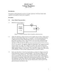
4-18. figure 4-2 is a simplified block diagram of the<br />
regulator used in the low-voltage supply. The series<br />
regulator acts as a variable resistance in the regulated<br />
output. A sensor (or differential amplifier) compares the<br />
output voltage with a reference voltage. The driver<br />
(emitter follower or amplifier) controls the bias on the<br />
series regulator, which effectively controls the series<br />
resistance. Any change in output voltage is fed back to<br />
the series regulator. The change in series resistance<br />
and the resulting voltage drop is opposite to the output<br />
voltage change, maintaining the output voltage at a<br />
constant level.<br />
Figure 4-2. Regulated Power Supply Block Diagram<br />
4-19. figure 8-10 is a schematic diagram of the low<br />
voltage power supply. The primary winding is wired<br />
through a rear panel power module for conversion to<br />
100-, 120-, 220- or 240-Vac operation. Line voltage is<br />
<strong>TM</strong> <strong>11</strong>-<strong>6625</strong>-<strong>2781</strong>-14&P<br />
Model 141T<br />
applied to the primary of TI through an on-off switch, a<br />
fuse and a thermal switch. Pilot lamp DS1, lights when<br />
power is applied to T1. Two shunt resistors are<br />
connected to the +248-volt supply to reduce series<br />
regulator power dissipation when high-current plug-ins<br />
are used. Each shunt is wired to a rear panel connector.<br />
The internal wiring of the plug-in determines whether the<br />
shunt is in the circuit or not.<br />
4-20. +100-Volt Supply. The ac voltage from the<br />
secondary ofT1 is rectified by A1CR5-AICR8 and<br />
partially filtered by C3 and A2R17. The resulting dc<br />
voltage is applied through the series regulator Q2, to the<br />
output. Differential amplifier A2Q4/A2Q5, compares the<br />
voltage across A2V1 with a sample of the output voltage.<br />
Any change in output voltage is applied to the base of<br />
driver A2Q3, which controls the bias on regulator Q2.<br />
Series regulator Q2, compensates for the change in<br />
output voltage by changing resistance and restores the<br />
output level to normal. The +100-volt output is adjusted<br />
by A2RllB and fuse A2F2 provides overload protection.<br />
4-21. -100-Volt Supply. Reference voltage for the -100-<br />
volt supply is taken from the output of the +100-volt<br />
supply. The reference voltage across A2R31 is<br />
compared with a sample of--100-volt output across<br />
A2R35. The error voltage sensed by differential amplifier<br />
A2Q7/A2Q8 is applied through driver A2Q6, and series<br />
regulator Q3. The series regulator brings the -100 volt<br />
supply back into proper balance with respect to the<br />
+100-volt supply. Ac voltage from T1 is rectified by<br />
A1CR9-A1CR12, partially filtered by C4/C5/A2R27, and<br />
the resulting dc voltage is applied by the series regulator<br />
Q3, to the -100-volt output. Regulation is obtained as in<br />
the +100-volt supply. A2R<strong>11</strong>C adjusts the -100-volt<br />
output, and fuse A2F3 provides overload protection.<br />
4-22. +248-Volt Supply. Sensor amplifier A2Q2, in the<br />
+248-volt supply senses any variation in the output<br />
voltage with respect to -100 volts. The error voltage is<br />
amplified by driver A2Q1, which applies corrective bias to<br />
series regulator Q1. A2RllA adjusts the +248-volt output<br />
and fuse A2F1 provides overload protection. A2CR4<br />
provides temperature compensation for A2Q2, and is<br />
normally forward-biased.<br />
4-23. -12.6-Volt Supply. Sensor amplifier A2 Q<strong>11</strong><br />
senses any variation of output voltage with respect to -<br />
100 volts and applies the error voltage to driver amplifier<br />
A2Q9. The driver increases signal current to the level<br />
required to control series regulator Q4. The -12.6-volt<br />
output is adjusted by A2R47A. Current limiter A2Q10 is<br />
a protective circuit for the series regulator and is<br />
normally biased off. If an overload occurs across the -<br />
12.6-volt output, the base of<br />
4-2
Theory<br />
A2(Q10 goes positive by the voltage drop across R<strong>11</strong>,<br />
minus the forward voltage drop across A2CR16, turning<br />
A2Q(10 on. The collector of A2Q10 is applied through<br />
A2Q9 to the base of series regulator Q4, reducing the<br />
current flowing through Q4. The current flows through<br />
an external overload which limits the current required to<br />
keep A2QIO on. Additional over-load protection is<br />
provided by fuse, A12F4.<br />
4-24. CALIBRATOR.<br />
4-25. The calibrator circuit (figure 8-10) consists of three<br />
parts: a tunnel diode (square wave generator), ;1<br />
transistor switch, and a calibration network.<br />
4-26. Input to tunnel diode A2CRI9, is applied through<br />
A2R5.0. The tunnel diode generates a square wave at<br />
line frequency. Transistor switch A2Q12, is off during<br />
the time of the positive half-cycle of the square wave<br />
(when the voltage at the base is close to zero), and the<br />
collector voltage is at a level set by breakdown diode<br />
A2VR6 and resistor A2R47B. When the negative-going<br />
portion of the square wave is applied to the base of<br />
A2Q12, the transistor increases conduction, effectively<br />
shorting the collector to ground. The output of the<br />
calibrator becomes zero. At the end of the negative input<br />
half-cycle (bias of A2Q12 returns to zero) the transistor is<br />
turned off, and the output returns to its previous value.<br />
4-27. Tunnel diode bias current is supplied through<br />
A2R51. The bias current sets an operating level for the<br />
diode which ,affects the symmetry of the square wave<br />
output. Cal adj A2R47R, is used to set the dc<br />
<strong>TM</strong> <strong>11</strong>-<strong>6625</strong>-<strong>2781</strong>-14&P<br />
Model 141T<br />
voltage at the collector of A2Q12 to -10 volts when the<br />
transistor is off Breakdown diode A2VR6 reduces the<br />
output impedance, and provides the temperature<br />
compensation for the circuit. Voltage divider A2R;54 ,’<br />
A2R55, reduces the 10-volt output to 1 . Roth 10- and I -<br />
volt outputs are available at the front panel of the<br />
instrument, and the 1-volt output is available to both<br />
plug-ins.<br />
4-28. HIGH-VOLTAGE SUPPLY.<br />
4-29. figure 4-3 is a block diagram of the high-voltage<br />
power supply. The output of a regulated transistor<br />
oscillator is stepped-up in voltage and applied to a series<br />
of high voltage rectifiers. The positive output of the<br />
voltage tripler is connected to the post-accelerator of the<br />
CRT. The negative output voltages are used in the gun<br />
assembly of the CRT and its associated controls. The Z-<br />
axis input can be used to apply intensity modulating<br />
signals to the CRT.<br />
4-30. figure 8-13 is a schematic diagram of the highvoltage<br />
supply and the CRT. Oscillator A2Q12 operates<br />
at a frequency of approximately 32 kHz. Any change in<br />
the output voltage is applied to A2Q15, which converts<br />
the voltage change to a current change. This current<br />
change is applied, by emitter follower A2Q14, to the base<br />
of the oscillator transistor. The amplitude of oscillations<br />
is changed in such a direction as to oppose the original<br />
output voltage change. high-voltage adjust A2R6:3 sets<br />
the amplitude of oscillation to produce the correct output<br />
voltage.<br />
Figure 4-3. High-Voltage Power Supply Block Diagram<br />
4-3
Theory<br />
4-31. Two separate negative supplies are used, one for<br />
the control grid of the CRT, and one to provide the CRT<br />
cathode and focusing voltages. Both supplies use halfwave<br />
rectifiers (A2CR23 and A2CR24). The unblanking<br />
gate from the horizontal plug-in (pin 1, J2) is applied to<br />
the return side of the grid supply, and changes the<br />
negative grid voltage by about +50 volts to unblank the<br />
trace. A positive pulse of about 20 volts will blank the<br />
trace when applied to Z-axis input. When Z-axis input is<br />
not used, S4 is set to INT to receive chopped blanking<br />
from a dual-trace plug-in.<br />
4-32. The voltage tripler circuit provides the 6.6 kV postaccelerating<br />
voltage applies to the CRT.<br />
4-33. The ASTIG adjustment, R8, adjusts the roundness<br />
of the spot, and the geometry adjustment, A2-R72, is<br />
used to optimize pattern shape.<br />
4-34. STORAGE CRT.<br />
4-35. Refer to figure 8-13 for the schematic diagram of<br />
the storage CRT, VI. The CRT contains the conventional<br />
electron (writing) gun, deflection plates, post-accelerator,<br />
and phosphor screen. In addition, there are two<br />
floodguns, a collimator, a collector mesh, and a storage<br />
mesh. These added elements make possible the<br />
variable persistence and storage functions of the<br />
instrument.<br />
4-36. Flood Guns. Two flood guns are located on the<br />
electron gun, outside of the horizontal deflection plates.<br />
Horizontal drivers, A6QI and A6Q2, prevent flood gun<br />
electrons from flowing through the deflection plates to<br />
the output stage of the plug-in. The guns operate<br />
continuously when the power switch is ON. An electron<br />
cloud, that is emitted by the flood guns, is accelerated<br />
toward the CRT screen by collimator and collector mesh<br />
voltages. These electrons make stored or persisting<br />
display visible. They are also used to erase stored and<br />
persisting displays.<br />
4-37 Collimator. The collimator is an internal coating<br />
along the tapered portion of the CRT. A positive voltage<br />
applied to the collimator focuses the flood-gun electrons.<br />
The flood-gun electrons are formed into a column<br />
perpendicular to, and approximately equal to the width of<br />
the CRT screen.<br />
4-38. Collector Mesh. The collector mesh is between<br />
the flood guns and the storage mesh (closer to the<br />
storage mesh). It is always positive with respect to the<br />
storage mesh except in the ERASE mode of operation;<br />
both are then at the same potential. In addition to<br />
accelerating flood gun electrons, the collector mesh also<br />
repels positive ions generated by the flood guns.<br />
4-39. Storage Mesh. The storage mesh is just behind<br />
the CRT screen and is coated with non-conducting<br />
material. It is statically held at a slightly positive potential<br />
(approximately +3 volts). When the electron beam from<br />
the writing gun strikes the mesh coating, secondary<br />
electrons are emitted. This secondary emission creates<br />
4-4<br />
<strong>TM</strong> <strong>11</strong>-<strong>6625</strong>-<strong>2781</strong>-14&P<br />
Model 141T<br />
a pattern of positive potential identical to the movement<br />
of the beam. Flood gun electrons are accelerated by this<br />
positive potential pattern and strike the phosphor screen,<br />
creating a visible display.<br />
4-40. The storage mesh is pulsed with pulses of<br />
approximately 10 microseconds duration. These pulses<br />
erase the positive pattern on the storage mesh by<br />
discharging the mesh coating. Time required for this<br />
erasing operation is determined by the pulse repetition<br />
rate. The positive pattern on the mesh may also be<br />
neutralized manually by connecting the collector and<br />
storage meshes (erase). The high positive potential<br />
(approximately +156 volts) allows more uniform<br />
discharging of the surface. When the storage mesh is<br />
disconnected from the collector mesh and returned to +3<br />
volts, the coated surface is at a uniformly equal potential<br />
of--9 volts. In both cases, the screen has no illumination.<br />
The pattern may be lost by the storage mesh fading<br />
positive and allowing the entire screen to be illuminated.<br />
This occurs when positive ions from the flood gun raise<br />
the surface potential of the storage mesh in random<br />
areas sufficiently to allow flood gun electrons to strike the<br />
screen.<br />
4-41. PULSE CIRCUIT.<br />
4-42. figure 4-4 is a simplified block diagram of the<br />
pulse circuit. The pulse circuit supplies pulses of<br />
variable repetition rate to control the operation of the<br />
CRT. The pulse timer generates a pulse which triggers<br />
the monostable multivibrator. The two outputs of the<br />
monostable multivibrator are applied to the flood gun<br />
driver and output pulser. The flood gun driver applies<br />
pulses to the accelerator of the CRT to control storage<br />
time of the display.<br />
4-43. The output pulser applies a positive voltage to the<br />
storage mesh of the CRT. The erase timer provides a<br />
signal to the monostable multivibrator and output pulser<br />
to generate an erase pulse and also triggers the blanking<br />
circuit. The blanking circuit energizes a relay in the high<br />
voltage supply which applies a blanking voltage to the<br />
CRT. The CRT collimator voltage is supplied by a linear<br />
amplifier and is controlled by the selection of the writing<br />
speed at the front panel.<br />
4-44. STD AND FAST MODES.<br />
S-E.S. Pulse Timer. figure 8-16 is a schematic diagram<br />
of the pulse circuit. Setting the front panel<br />
PERSISTENCE control, R10, determines the amount of<br />
current available from the pulse timer current source,<br />
A5QI . A5C1 charges to a potential which turns A’5Q2<br />
on. A5CI discharges through A5Q2, A5-Q2 turns off,<br />
and A5Cl again begins to build a ramp voltage. The<br />
repetition rate of this action is controlled by the setting of<br />
the front panel PERSISTENCE con-
Theory<br />
<strong>TM</strong> <strong>11</strong>-<strong>6625</strong>-<strong>2781</strong>-14&P<br />
Model 141T<br />
Figure 4-4. Pulse Circuit Block Diagram<br />
trol. The output of A5Q2 is a 0 to 10 kHz pulse with a<br />
very sharp spike which is coupled through A5C2 to the<br />
monostable multivibrator. This portion of the pulse circuit<br />
is active in all modes.<br />
4-46. Monostable Multivibrator. The multivibrator,<br />
A5Q3/ASQ4, operating in a monostable state, receives<br />
pulses from the pulse timer, and applies a negativegoing<br />
pulse (approximately 10 usec wide) to A5CR3.<br />
4-47. Output Pulser. The negative-going pulse from the<br />
monostable multivibrator allows A5CR7 to become<br />
forward biased with a current controlled by the setting of<br />
the fast write depth adjustment A5R14A, or the standard<br />
write depth adjustment A5R1OA, depending on whether<br />
FAST or STD mode is being used. This current pulse is<br />
amplified and converted to a voltage pulse by<br />
4-5<br />
A5Q7/A5Q8 and applied to the storage mesh backing<br />
electrode.<br />
4-48. Erase Timer. The erase timer circuits are in a<br />
quiescent state during operation in either STD or FAST<br />
write modes. When erase timer A5Q9 is turned off,<br />
A5CR8 in the erase pulse shaping circuit is back biased.<br />
This effectively disconnects the erase timer circuit from<br />
the output pulser.<br />
4-49. When operating in the STD mode, at the instant<br />
the ERASE pushbutton is pressed, figure 4-5 point A, the<br />
following actions take place simultaneously:
Theory<br />
a. The collector mesh potential of +156 volts is<br />
applied to the junction of A5R27 and A5R28. This<br />
voltage causes A5CR14 to become reverse-biased,<br />
which protects A5Q7 and A5Q8.<br />
b. The +156 volts applied to A5R27 turns A5Q9 on<br />
which charges A5C8 to 0 volts. This action turns on<br />
ASQI5 A.-Ql6 through A5R53 which blanks the CRT<br />
write gun by means of a relay closure on the high voltage<br />
power supply board.<br />
c. Zero volts on A5R17 reduces the output of<br />
amplifier A5Q7 A5Q8 by approximately -12 volts.<br />
ASQ18 turns on, turning A5Q19 off. A5Q3 is turned on<br />
by current through A5R7 which allows amplifier A5Q7 A.-<br />
Q8 to reach its full output amplitude, less the reduction in<br />
amplitude due to the current through A5R17. The result<br />
is approximately -4 volts. The erase multivibrator<br />
A5Q20/A5Q21 begins to free run at approximately 100<br />
Hz. This signal is amplified through A5Q22 to drive<br />
A5Q12 and A5Q13 for an alternating collimation voltage<br />
to better erase the CRT.<br />
d. The circuits remain in this state as long as the<br />
ERASE pushbutton is pressed.<br />
4-50. When the ERASE pushbutton is released, figure<br />
4-5 point B, the following circuit actions occur<br />
simultaneously:<br />
a. ASQ9 is turned off.<br />
b. The voltage on A5C8 begins to discharge from<br />
approximately 0 volts toward -12.6 volts, figure 4-5 point<br />
D.<br />
<strong>TM</strong> <strong>11</strong>-<strong>6625</strong>-<strong>2781</strong>-14&P<br />
Model 141T<br />
pulser returns to the quiescent voltage of approximately<br />
3.3 volts. A5Q20 and A5Q21 stop running and the<br />
collimator voltage returns to the nominal value.<br />
4-51. Operation of the ERASE pushbutton when in the<br />
FAST mode is as described in paragraphs 4-49 and 4-50<br />
except that the storage mesh potential drops less after<br />
releasing the ERASE pushbutton and remains constant<br />
until A5C8 voltage decreases to -12.6 volts (figure 4-5<br />
points C and B). This action results from the forwardbiasing<br />
of A5CR29 which prevents current flow through<br />
A5CR8 and allows the output of A5Q7 and A5Q8 to go to<br />
its maximum level as determined by the fast write depth<br />
adjustment.<br />
4-52. At this point, all pulse circuits have returned to the<br />
condition they were in prior to pressing the ERASE<br />
pushbutton, and pulses from the pulse timer may again<br />
be applied to the storage mesh backing electrode.<br />
4-53. PULSE CIRCUIT:STORE MODE.<br />
4-54. Flood Gun Grid Control. Pressing the STORE<br />
pushbutton removes +156 volts from A5R19 and A5R50.<br />
This turns off A5Q5 and pulses from the monostable<br />
multivibrator are now coupled through A5C5 to the base<br />
of A5Q6. During the 10 usec that A5Q4 output goes<br />
positive, A5C5 is charged. When A5Q4 output goes<br />
negative, A5CR9 is back biased and A5Q6 turns off.<br />
The collector of A5Q6 goes positive until A5C5 is<br />
charged and turns A5Q6 back on. This pulse has a<br />
duration of approximately 60 usec. This pulse is applied<br />
to the flood gun accelerator, which turns the flood gun on<br />
for the pulse duration.<br />
4-55. The repetition rate of these positive pulses at the<br />
collector of A5Q6 is now determined by the setting of the<br />
STORE TIME control, R9, which replaces the<br />
PERSISTENCE control when the STORE pushbutton is<br />
pressed.<br />
c. The voltage change across A5R17/A5VR1<br />
causes the output of amplifier A5Q7/A5Q8 to increase<br />
from about -4 volts. The increase is in the form of a<br />
ramp to the output voltage determined by the standard<br />
write depth adjustment A5R10. When A5VR1 is no<br />
longer conducting, the ramp stops, figure 4-5 point E.<br />
d. A5Q3 is held in saturation by A5R7. This<br />
establishes the output voltage of amplifier A5Q7/A5Q8 at<br />
approximately 8 volts.<br />
e. When A5C8 voltage decreases to -12.6 volts,<br />
ASQ3 turns off (figure 4-5 point F), and the output<br />
4-56. The write gun is blanked by A5Q16 through the<br />
action of A5Q14 and A5Q15.<br />
4-57. PULSE CIRCUIT:CONVENTIONAL MODE.<br />
4-58. When the CONV pushbutton is pressed, a +100-<br />
volt potential is removed from A5R25. A5CR15 is<br />
forward biased by -100 volts through A5R26, A5-CR14,<br />
and R25. This voltage divider sets the storage mesh<br />
backing electrode to approximately 29 volts. A5-CR13 is<br />
reverse-biased, preventing output pulser signals from<br />
passing through. This action produces conventional<br />
oscilloscope operation by disabling the variable<br />
persistence mode.<br />
4-6
Model 141T<br />
4-59. When the oscilloscope is turned off, a display<br />
stored on the CRT is protected from unintentional<br />
erasure by A5Q17 and the associated circuit.<br />
4-60. TRACE ALIGN.<br />
4-61. The trace align coil L1, is located around the CRT<br />
near the screen. Adjustment of TRACE ALIGN R7A/B,<br />
changes the magnitude and direction of current through<br />
the coil and rotates the trace into alignment with the CRT<br />
graticule.<br />
4-62. PLUG-IN KIT FABRICATION.<br />
4-63. The HP Model 10477A and Model 10487A<br />
Accessory Plug-ins are blank plug-in units for the<br />
instrument. These two units permit the user to design<br />
his own special-purpose circuits. Current available from<br />
<strong>TM</strong> <strong>11</strong>-<strong>6625</strong>-<strong>2781</strong>-14&P<br />
Theory<br />
each of the instrument power supplies is shown in table<br />
4-1. Do not exceed the current capabilities in table 4-1.<br />
Table 4-1. Current Capability<br />
Supply Voltage and Current Available at<br />
J1/J2 pin number each Jack (J1 and J2)<br />
+248 Vdc 9 0-50 ma<br />
+248 Vdc 9 50-100ma (pin 2 must<br />
be wired to pin 3 in<br />
the plug in.)<br />
+100 Vdc 2 0-137.5 ma<br />
-100 Vdc 6 10-200ma<br />
-12.6 Vdc 21 0-0.9 amps<br />
6.3Vac 13-14 0-3.25amps<br />
4-7/4-8
Model 141T<br />
5-1. INTRODUCTION<br />
SECTION V<br />
PERFORMANCE CHECK AND ADJUS<strong>TM</strong>ENTS<br />
5-5. PERFORMANCE CHECK<br />
<strong>TM</strong> <strong>11</strong>-<strong>6625</strong>-<strong>2781</strong>-14&P<br />
Performance Check<br />
5-2. This section contains step-by-step procedures for<br />
checking the instrument specifications as given in table<br />
1-1 of this manual. A table (performance check record)<br />
is provided at the end of the performance check for<br />
recording the measurements obtained in the first running<br />
of the procedure. This record may be used to compare<br />
measurements taken at later dates with the original. The<br />
procedures for making all internal adjustments are<br />
covered in paragraphs 5-21 through 5-33. A photograph<br />
showing the locations of all internal adjustment controls<br />
is presented in figure 5-1.<br />
5-3. TEST EQUIPMENT<br />
5-4. Test equipment required for procedures in this<br />
section is listed in table 5-1. Test equipment equivalent<br />
to that recommended may be substituted, provided it<br />
meets the required characteristics listed in the table. For<br />
best results, use recently calibrated test equipment. Use<br />
a non-metallic screwdriver when making adjustments.<br />
5-6. The following subparagraphs describe procedures<br />
to determine whether or not the instrument is operating<br />
within the specifications of table 1-1. This check can be<br />
used as part of an incoming inspection, as a periodic<br />
operational test, or to check calibration after repairs or<br />
adjustments have been made. Any one of the following<br />
checks can be made separately if desired.<br />
5-7. The first time the performance check is made, enter<br />
the results on the performance check record at the end<br />
of the procedure. Remove the record from the manual<br />
and file it for future reference. Be sure to include the<br />
instrument serial number on the record for identification.<br />
5-8. PRELIMINARY SETUP<br />
a<br />
Install time base and vertical plug-ins<br />
b<br />
sweep<br />
Adjust time base for a free-running 1 msec/div<br />
Table 5-1. Recommended Test Equipment<br />
Type<br />
Instrument Characteristics Required<br />
Required<br />
For<br />
Model<br />
Voltmeter HP 738BR HO1 Accuracy: 0.1% Calibrator<br />
Calibrator Output Voltages: 1V,10V Performance Check<br />
Calibrator<br />
Adjustment<br />
Digital HP 3439A Accuracy: 0.1% Low Voltage Power<br />
Voltmeter with HP 3441A Voltage Range: ±300V Supply Adjustment<br />
Plug-in Input Impedance: 10.2M1<br />
High Voltage Power<br />
Supply Adjustment<br />
Voltage HP K05 3440A Accuracy: 1%<br />
Divider Probe Division Ratio: 1000:1 High Voltage Power<br />
Maximum Voltage: 4 KV<br />
Supply Adjustment<br />
Oscillator HP 204C Waveform: Sine Wave Geometry Adjustment<br />
Frequency: 80 Hz to 400<br />
Pulse Circuit<br />
kHz<br />
Adjustment<br />
5-1
Model 141T<br />
<strong>TM</strong> <strong>11</strong>-<strong>6625</strong>-<strong>2781</strong>-14&P<br />
Performance Check<br />
c<br />
d<br />
Set vertical plug-in input switch to off or ground<br />
Set Model I -<strong>11</strong> T controls as follows:<br />
INTENSITY.......................................... MIN<br />
PERSISTENCE ................................... MIN<br />
WRITING SPEED ............................... STD<br />
e Turn instrument on and allow a 15 minute warmup<br />
period.<br />
CAUTION<br />
The INTENSITY control should never be<br />
set high enough to cause blooming.<br />
Excessive intensity can permanently<br />
damage the CRT storage mesh.<br />
5-2<br />
5-13. TRACE ALIGN<br />
a Perform preliminary setup (paragraph 5-8<br />
b Adjust TRACE AI,IGN until trace is parallel to<br />
center graticule line. This condition should occur near<br />
center of adjustment range.<br />
5-14. CALIBRATOR<br />
a Perform preliminary setup (paragraph 5-8)<br />
h<br />
c<br />
Connect voltmeter calibrator to vertical input<br />
Set voltmeter calibrator for output of 1V p-p<br />
5-9. BEAM FINDER<br />
d<br />
Set vertical amplifier sensitivity to .I V/div<br />
NOTE<br />
The BEAM FINDER returns beam to CRT<br />
screen regardless of deflection potentials<br />
when used with the 1400-series timedomain<br />
plug-ins.<br />
When used with the 8550-series<br />
frequency-domain plug-ins, the REAM<br />
FINDER has no function.<br />
a Perform preliminary setup (paragraph 5-8)<br />
b Rotate vertical and horizontal position controls<br />
fully cw<br />
c Press and hold REAM FINDER pushbutton while<br />
slowly rotating iNTENSITY cw until a trace becomes<br />
visible.<br />
d BEAM FINDER should return trace to CRT<br />
regardless of position of vertical or horizontal controls.<br />
e Adjust vertical and horizontal position controls<br />
until trace is centered on CRT display.<br />
f<br />
Release BEAM FINDER<br />
5-10. Paragraphs 5-<strong>11</strong> through 5-14 contain preliminary<br />
operational checks of performance characteristics not<br />
listed in table 1-1. Because these characteristics are not<br />
specified, stated : results are approximate.<br />
5-<strong>11</strong>. FOCUS AND ASTIG.<br />
5-12. FOCUS and ASTIG controls should give a sharply<br />
defined trace when set to approximately midrange<br />
positions. Adjust for sharpest trace possible and leave in<br />
that position.<br />
5-2<br />
e Adjust vertical vernier to display exactly 8 di,<br />
isions of vertical deflection.<br />
f<br />
g<br />
input.<br />
h<br />
Disconnect voltmeter calibrator<br />
Connect Model 141T CAL IV output to vertical<br />
Observe deflection of 8 ±0.1 division<br />
i Repeat steps a through g, using 10 volts from<br />
the voltmeter calibrator, 1 V/'div vertical sensitivity, and<br />
CAI, 10V.<br />
5-15. VARIABLE PERSISTENCE<br />
a Perform preliminary setup (paragraph 5-8)<br />
b<br />
Adjust INTENSITY for normal viewing level<br />
c Set time base to 2 sec/div and observe that trace<br />
line disappears and that spot develops a short tail.<br />
d Slowly adjust PERSISTENCE cw and note that<br />
tail lengthens.<br />
e. Rotate PERSISTENCE fully cw and turn INTENSITY<br />
fully ccw.<br />
f. Observe that trace remains visible for one minute.<br />
5-16. WRITING SPEED, FAST<br />
a Perform preliminary setup (paragraph 58)<br />
b Set PERSISTENCE to MAX<br />
c Set time base for 1 usec/div sweep<br />
d Set time base for single sweep
Model 141T<br />
<strong>TM</strong> <strong>11</strong>-<strong>6625</strong>-<strong>2781</strong>-14&P<br />
Adjustments<br />
e Press FAST pushbutton and press ERASE.<br />
Observe that background appears foggy.<br />
F Repeatedly erase and trigger a single sweep,<br />
increasing INTENSITY slightly each time, until trace<br />
writes and remains visible for 15 seconds.<br />
5-17. STORE TIME, FAST.<br />
a Perform preliminary setup (paragraph 5-8).<br />
b Rotate STORE TIME to MAX.<br />
c Press ERASE.<br />
D Trigger a single sweep and immediately press<br />
STORE.<br />
e After 15 minutes rotate STORE TIME to MIN.<br />
Trace should still be visible.<br />
5-18. WRITING SPEED, STANDARD.<br />
a Perform preliminary setup (paragraph 5-8).<br />
b Press STD.<br />
c Set time base for 50 usec/div sweep.<br />
d Repeatedly erase and trigger a single sweep,<br />
increasing INTENSITY slightly each time, until trace<br />
writes and remains visible for one minute.<br />
5-19. STORE TIME, STANDARD.<br />
a Perform preliminary setup (paragraph 5-8).<br />
b Rotate STORE TIME to MAX.<br />
c Press ERASE.<br />
d Trigger a single sweep and immediately press<br />
STORE.<br />
e After 2 hours, rotate STORE TIME to MIN.<br />
Observe that trace is still visible.<br />
5-20. This completes the Performance Check. If the<br />
instrument does not meet specifications, the adjustment<br />
procedure which follows should be done. If this does not<br />
result in satisfactory performance, refer to Section VIII<br />
for maintenance and troubleshooting information.<br />
5-21. ADJUS<strong>TM</strong>ENTS.<br />
5-22. The following paragraphs describe procedures to<br />
calibrate the instrument so that it will perform as<br />
specified in table 1-1. The entire adjustment procedure<br />
can be done in sequence, or any separate adjustment<br />
can be calibrated by following the steps outlined<br />
in the appropriate paragraph. The locations of<br />
adjustment controls are shown in figure 5-1, a<br />
photograph included at the end of the section on a<br />
foldout page<br />
5-3<br />
5-23. Use a nonmctallic screwdriver and recently<br />
calibrated test equipment with characteristics as<br />
specified in tab)le 5-I. After adjustments are complete,<br />
check instrument performance by doing the performance<br />
check procedure at the beginning of this section. If<br />
difficulty is encountered in making any adjustment, refer<br />
to Section VIII for troubleshooting procedures.<br />
5-24. PRELIMINARY SETUP.<br />
a Install plug-ins in both compartments. Proper<br />
power supply regulation may not occur without load<br />
connected.<br />
b Remove top, bottom, left side and high voltage<br />
deck covers. All internal adjustments are identified in<br />
figure 5-1.<br />
Voltages present in the power supplies are<br />
dangerous.<br />
c Rotate INTENSITY, PERSISTENCE, and<br />
STORE TIME fully ccw.<br />
d Turn instrument on and allow 15 minutes warmup<br />
period.<br />
5-25. LOW VOLTAGE POWER SUPPLY<br />
ADJUS<strong>TM</strong>ENT.<br />
a Perform preliminary setup (paragraph 5-24).<br />
b Adjust low voltage regulators as indicated in<br />
table 5-2.<br />
NOTE<br />
Because +100-volt supply is a reference<br />
for the other mainframe supplies it must<br />
be set first. Voltage may be measured on<br />
any terminal with wire color shown in table<br />
5-2.<br />
c Recheck all supplies before proceeding. The<br />
+IOOV supply must be set as near to +1OOV as<br />
possible.<br />
5-26 HIGH VOLTAGE POWER SUPPLY<br />
ADJUS<strong>TM</strong>ENT.<br />
a Perform preliminary setup (paragraph 5-24).<br />
b Monitor +100 Vdc supply with digital voltmeter<br />
using voltage divider probe. Note exact reading
Model 141T<br />
<strong>TM</strong> <strong>11</strong>-<strong>6625</strong>-<strong>2781</strong>-14&P<br />
Adjustments<br />
Table 5-2. Low Voltage Power Supply Adjustment<br />
SUPPI.Y ADJUST LIMIT MEASURE POINT<br />
WIRE COLOR<br />
+1OOV A2R<strong>11</strong>B 1V WHITE/RED<br />
-100V A2R<strong>11</strong>C t1V VIOLET<br />
+248V A2R<strong>11</strong>A ±2.5V RED<br />
-12.6V A2R47A ±0.13V WHITE/VIOLET<br />
c Multiply value obtained in step b by 23.50.<br />
d While monitoring high voltage,--2350VM( ITOR<br />
POINT (4), set HV adj. A2R63, to obtain voltage reading<br />
equal to result obtained in step (-2350 i25V).<br />
e. This procedure will set high voltage wit 1%,<br />
provided +1OOV supply is set to indicate exam +IOOV<br />
on digital voltmeter.<br />
5-27. INTENSITY LIMIT ADJUST.<br />
NOTE<br />
Method A must be used for Model 141T’s<br />
with 1400-Series vertical and time-base<br />
plug-ins. Method B must be used for Model<br />
141T’s with spectrum analyzer plug-ins.<br />
Method A.<br />
a Turn power off.<br />
b Remove 1400-Series plug-ins.<br />
c Short pins 1 and 2 of upper compartment<br />
connector, J2, together.<br />
l<br />
Replace plug-ins.<br />
Method B.<br />
a Turn power off.<br />
b Install spectrum analyzer plug-ins.<br />
c Set plug-ins for 0.5 ms SCAN mode and AUTO<br />
trigger.<br />
d Turn power ON.<br />
e Turn intensity limit A2R65 full ccw, extinguishing<br />
trace.<br />
f Set INTENSITY to <strong>11</strong> o’clock position.<br />
g Press STD pushbutton.<br />
h Set PERSISTENCE to MIN.<br />
i Turn A2R65 slowly cw until crest of trace is<br />
bright with rest of trace barely visible as shown in figure<br />
5-1A<br />
Voltages present in the high voltage supply<br />
are dangerous.<br />
d Turn power ON.<br />
e Set intensity limit A2R65 fully ccw.<br />
f Set INTENSITY to <strong>11</strong> o’clock position.<br />
g Press STD pushbutton.<br />
h Slowly adjust A2R65 cw until a spot is just<br />
visible.<br />
i Turn INTENSITY fully ccw.<br />
j Turn power off.<br />
k Remove short from upper compartment<br />
connector J2.<br />
5-4<br />
Figure 5-1A. Spectrum Analyzer Intensity Limit Adjust
Model 141T<br />
5-28. GEOMETRY<br />
a Perform preliminary setup (paragraph 5-24)<br />
b Set controls as follows:<br />
trigger level ..........................................auto<br />
trigger source ......................................int (+)<br />
sweep time...........................................0.5 msec/div<br />
WRITING SPEED ................................STD<br />
PERSISTENCE....................................MIN<br />
c Slowly adjust INTENSITY for normal viewing<br />
level.<br />
d Press ERASE.<br />
e Press CONV.<br />
f Adjust TRACE ALIGN and vertical position<br />
controls so that trace is parallel to center graticule<br />
line<br />
g Connect 400-kHz oscillator output to vertical<br />
amplifier input<br />
h Adjust vertical deflection factor to obtain slightly<br />
under 8 divisions of vertical deflection.<br />
CAUTION<br />
If it is necessary to increase intensity, do<br />
so only in STD mode. There is no<br />
indication of excessive beam intensity<br />
while in the CONV mode and CRT mesh<br />
can be burnt.<br />
i Adjust geometry A2R72 for best compromise<br />
between distortion of vertical and horizontal edges of<br />
display. Vertical and horizontal controls may be adjusted<br />
to permit viewing of edges.<br />
j<br />
k<br />
Set INTENSITY fully ccw<br />
Disconnect oscillator<br />
5-29. CALIBRATOR ADJUS<strong>TM</strong>ENT<br />
a Perform preliminary setup (paragraph 5- 24)<br />
b Press STD<br />
c Connect O1V p-p output of voltmeter calibrator<br />
to vertical amplifier input<br />
d Set vertical amplifier deflection sensitivity<br />
to 1 V/div<br />
5-5<br />
<strong>TM</strong> <strong>11</strong>-<strong>6625</strong>-<strong>2781</strong>-14&P<br />
Adjustment<br />
e Slowly increase INTENSITY to normal viewing<br />
level<br />
f Adjust vertical amplifier vernier to display<br />
exactly 8 divisions of vertical deflection<br />
g Disconnect voltmeter calibrator<br />
h Connect Model 141T O1V CAL output to vertical<br />
amplifier input<br />
i Set cal adj A2R47B to obtain exactly 8 divisions<br />
of vertical deflection<br />
5-30. PULSE CIRCUIT ADJUS<strong>TM</strong>ENTS<br />
5-31 FAST MODE ADJUS<strong>TM</strong>EAITS<br />
a Perform preliminary setup (paragraph 5-24)<br />
b Press FAST pushbutton<br />
c Turn INTENSITY and PERSISTENCE fully ccw<br />
d Set time base for single sweep so that sweep will<br />
not occur during this portion of procedure<br />
e Set fast write depth adj A5R14A fully ccw<br />
f Set fast coll adj A5R14B so that entire flood<br />
gun illumination pattern is visible<br />
g Adjust flood gun grid adj A5R14C to obtain<br />
brightest and most uniform illumination<br />
h Adjust fast coll adj A5R14B so that flood<br />
gun illumination just fills graticule<br />
i Set PERSISTENCE to MAX<br />
j Press ERASE<br />
k Adjust fast write depth adj A5R14A slowly cw in<br />
small increments, erasing after each step, until a good<br />
compromise between no light and saturated brightness is<br />
obtained on CRT after ERASE button is pressed.<br />
I Adjust fast coll adj A5R14B in small increments.<br />
Erase and readjust fast write depth adj A5R14A (step k)<br />
between increments until uniform fogging is obtained.<br />
m Set controls as follows:<br />
sweep time ......................................... 0.2 msec/div<br />
sweep ........................................normal (recurrent)<br />
INTENSITY.................................................. fully cc<br />
PERSISTENCE ................................................ MIN<br />
n Connect 4 kHz oscillator sine-wave output to<br />
vertical amplifier input
Model 141T<br />
o Adjust vertical gain t(J obtain 8 divisions of<br />
vertical deflection<br />
p<br />
Adjust INTENSITY for normal viewing level<br />
q Increase vertical gain by a factor of 10. Do not<br />
adjust INTENSITY.<br />
r<br />
s<br />
Set time base for single sweep operation<br />
Set PERSISTENCE to MAX<br />
t Increase INTENSITY gradually while erasing<br />
CRT until beam writes evenly, but not to point where<br />
beam is always on.<br />
u<br />
Press ERASE pushbutton until no trace remains<br />
v Erase, and immediately arm and trigger a single<br />
sweep The resulting waveform should be visible inside a<br />
6 x 8 division rectangle for 15 seconds. If not, rotate fast<br />
write depth adj A5R14A clockwise until it is. If CRT still<br />
will not hold trace for 15 seconds, return to step g and<br />
reduce the illuminated area to no less than a centered<br />
7.6 x 9.5 division rectangle.<br />
w Rotate fast write depth adj A5RI14A ccw in<br />
small increments. leave ARI14A at point farthest ccw that<br />
permits trace to remain visible for 15 seconds.<br />
5-32. STD MODE ADJUS<strong>TM</strong>ENTS<br />
a Perform preliminary setup (paragraph 5-24)<br />
b<br />
c<br />
Set INTENSITY fully ccw<br />
Set PERSISTENCE to MIN<br />
d. Set std write depth adj A5RIOA fully ccw<br />
e. Press STD pushbutton<br />
f Set time base to single sweep to prevent beam<br />
from sweeping<br />
<strong>TM</strong> <strong>11</strong>-<strong>6625</strong>-<strong>2781</strong>-14&P<br />
Adjustments<br />
h Turn std coil adj ASRIOB fully ccw and that<br />
slowly cw until screen is illuminated to point I n from<br />
aluminum ring Collimator dimples may protrude ’3 mm<br />
from aluminum ring but in no may come into graticule<br />
area<br />
i<br />
j<br />
Set time base for sweep of 10 msec/div<br />
Set time base, fir recurrent sweep<br />
k Connect 80-lIz oscillator sine-wave output<br />
vertical amplifier input<br />
I Adjust vertical gain to obtain 8 divisions vertical<br />
deflection<br />
m<br />
Adjust INTENSITY for normal viewing level<br />
n Increase vertical gain by factor of 10.Do not<br />
adjust INTENSITY’<br />
o<br />
p<br />
Set time base for single sweep operation<br />
Set PERSISTENCE to MAX<br />
q Increase INTENSITY gradually while eraser<br />
CRT until beam writes evenly, but not to the poi where<br />
beam is always on.<br />
r Press ERASE. If CRT does not erase co<br />
ple.tely, rotate std i rite depth adj A5RIOA, cw<br />
10increments, pressing ERASE pushbutton each time.<br />
Repeat until CRT erases completely.<br />
s. If CRT will not erase completely, rotate flo gun grid<br />
adj ASRIl4C, cw in small increments, repeating FAST<br />
MODE an(l STD MODE adjustments procedures with<br />
each flood gun grid adj increments until CRT erases<br />
properly.<br />
t. Press ERASE Immediately arm and trigger a single<br />
sweep The waveform should be visible i side a 7 x )<br />
division rectangle for 60 seconds without positive fade}<br />
(screen turning bright green). If trace is not continuous,<br />
adjust std write depth adj A5RIC cw in small increments<br />
until continuous trace is obtained<br />
g<br />
Press ERASE for one second and release<br />
5-33. This completes adjustment procedures. If<br />
satisfactory operation cannot be obtained, refer to<br />
Section VIII for troubleshooting information<br />
5-6
Model 141T<br />
<strong>TM</strong> <strong>11</strong>-<strong>6625</strong>-<strong>2781</strong>-14&P<br />
Adjustments<br />
Figure 5-1. Adjustment Location<br />
5-7
PERFORMANCE CHECK RECORD<br />
141T<br />
<strong>TM</strong> <strong>11</strong>-<strong>6625</strong>-<strong>2781</strong>-14&P<br />
Instrument Serial Number<br />
Paragraph Check Specification Measured<br />
Reference<br />
5-9 BEAM FINDER Returns trace to YES NO<br />
screen.<br />
5-14 CALIBRATOR 8 divisions ±O.1 Divisions<br />
division.<br />
5-15 VARIABLE PERSISTENCE Spot develops short YES NO<br />
tail.<br />
Trace remains visible<br />
for one minute. YES NO<br />
516 WRITING SPEED, FAST Trace writes and<br />
remains visible for<br />
15 seconds YES NO<br />
5-17 STORE TIME, FAST Trace can be stored<br />
for 15 minutes YES NO<br />
5-18 WRITING SPEED, STANDARD Trace writes and<br />
remains visible for<br />
one minute YES NO<br />
5-19 STORE TIME, STANDARD Trace can be stored<br />
for 2 hours YES NO<br />
5-8
Model 141T<br />
SECTION VI<br />
REPLACEABLE PARTS<br />
<strong>TM</strong> <strong>11</strong>-<strong>6625</strong>-<strong>2781</strong>-14&P<br />
Replaceable Parts<br />
6-1. INTRODUCTION<br />
6-2. This section contains information for ordering<br />
replacement parts. The abbreviations used in the parts<br />
list are described in table 6-1. Table 6-2 lists the parts in<br />
alphanumeric order by reference designator and includes<br />
the manufacturer and manufacturer’s part number Table<br />
6-3 contains the lists of manufacturers codes. Table 6-4<br />
cross-references part numbers to NSN’s.<br />
6-3. ORDERING INFORMATION<br />
6-4 To obtain replacement parts from Hewlett-Packard,<br />
address order or inquiry to the nearest Hewlett Packard<br />
Sales/Service Office and supply the following<br />
information:<br />
a<br />
b<br />
c<br />
d<br />
Instrument model and serial number<br />
HP part number of items(s<br />
Quanity of part(s) desired<br />
Reference designator of part(s<br />
6-5. To order a part not listed in the table, provide the<br />
following information:<br />
a Instrument model and serial number<br />
b Description of the part, including function and<br />
location in the instrument.<br />
c<br />
Quanity desired.<br />
Table 6-1. Abbreviations for Replaceable Parts List<br />
6-1
Model 141T<br />
TABLE 6-2.Replaceable Parts<br />
<strong>TM</strong> <strong>11</strong>-<strong>6625</strong>-<strong>2781</strong>-14&P<br />
Reference<br />
Designation<br />
HP Part<br />
Number<br />
Qty Description Mfr<br />
Code<br />
Mfr Part Number<br />
A0<br />
A1 00141-66515 DIODE BOARO ASSY 28480 00141- 665t5<br />
A2 00141-66519 POWER SUPPLY 80ARD ASSA 28480 00141- 66519<br />
A3 00141-6<strong>11</strong>01 HICH VOLT AE TRIPLER ASSY 28480 10141- 6<strong>11</strong>01<br />
A4<br />
NOT ASSIGNED<br />
A5 00141-66520 PULSE CIRCUIT BOARD ASSY 28480 00141- 66520<br />
A6 00141-66502 HORIONTAL DRIVER ASSY 28480 00141- 6650<br />
A7 5060-9421 ASSIYPDWER MODULE 28480 5060- 9421<br />
B1 3160-0252 1 FANITURE AXIAL <strong>11</strong>5V 50160HZ 16W 92702 WS2107FL-570<br />
C1 0183-0154 1 C:FXD ELE CT 43OIUF .10010: 2508-CW 56289 037361<br />
C2 0180-0012 1 C:FXD ELECT 2X2O UF 45DVDCW 56289 032440<br />
C3 0180-0046 1 C:FXO ELECT 60OUF 520VDCW 56289 032569<br />
C4 0180-0214 1 C:FXD ELECT 275 UF-50-102 20OVDCW 56289 D 36037-DFP<br />
C5 0180-0093 1 C:FXO ELECT 2OUP 1SOVDCW 56289 033193<br />
C6 0180-0213 1 C:FXD ELECT 5000 UP +75-10: 25VDCW 56289 D39556<br />
CAI 1901-0032 2 DIODE:SILICON tN3209 04<strong>11</strong>3 IN3209<br />
CR2 1901-0032 DIODE:SILICON 1N3209 04713 143209<br />
DS1 1450-0419 1 LIGHT:INDICATOR SELECTED NE-2H 28480 145041g<br />
J1 1251-0054 2 CONNECTOR; FEMALE 24-CONTACT 28480 1251-0054<br />
J2 1251-0054 CONNECTOR; FEMALE 24-CONTACT 28480 1251-0054<br />
J3 1251-2357 1 SOCKET.3-PIN MALE POWER RECEPTACLE 82389 EAC-301<br />
J4 1251 0202 2 CONNECTOR BANANA JACK 83330 2218<br />
J5 1251 0202 CONNECTOR BANANA JACK 83330 221B<br />
J6 1210 0083 CONNECTOR BNC 0260 31221 1020<br />
J7 1510 00381 BINDINGPOST 28480 50,O38<br />
J8 1251 2366 1 CONNECTOR RANDPBPOSITIONS 71468 DCM IW8S<br />
J9 1251 2367 1 CONNECTOR R & P.R INSERT POSITION 71468 oCM 8WRP<br />
J10 1251 <strong>11</strong>286 1 CONNECTOR R& P 12 CONTACT FEMALE 71468 6CM 17W5<br />
JIDE 1 1251 0780 3 INSERT R&P CONNECTOR 08718 DCM 537425001<br />
J<strong>11</strong> 1251 1221 1 CONNECTOR R & P 12 CONTACT MALE 7178 DCM 17W5P<br />
J<strong>11</strong>EI 12510179 3 INSERT R&PCONNECTOR 1468 DM 537405001<br />
L1 5060-0435 1 COIL:ALIGNMENT Z AXIS 28480 5060-0435<br />
P1 5060-0736 2 FRAME ASSY 28480 50600736<br />
8P3 00141-60205 1 PANEL:FRONT 28480 00141-6020 5<br />
MP4 5060-0222 2 HANDLE ASSYSH SIDE 28480 5060-0222<br />
IAP6 5060-8735 2 RETAINER HANDLE ASSY:OLIVE GRAY(STDi 28480 50608735<br />
MPB 5060-0767 5 FOOT ASSY:FM 28480 5060-0767<br />
-llfl3 36-a ay4z 1 #TAZO 3.3m 7<br />
MP14 5000-8727 2 SIDE COVER 28480 5000-8727<br />
MP16 5060-8589 1 COVER ASSY:TOP 16LIOLIYE GRAYI 28480 506018589<br />
MP17 5060-8713 1 BOTTOM C,VER ASSY:16L FN(NINT G6R1 A 28480 5060-8713<br />
mPlA 00141-60206 1 PANEL ASSY:REAR 28480 00141-60206<br />
MP22 00140-24710 1 TOP PANEL SUPPORT 28480 0014024710<br />
PP23 00140247<strong>11</strong> I BOTTOM PANEL SUPPORT 28480 00140247<strong>11</strong><br />
"P24 00141-67401 1 KNOB:PUSHOUTTON ERASE 28480 00141-67401<br />
MP25 00141-67402 1 K(NO8:PUSHBUTTON FAST 28480 00141-67402<br />
MP26 00141-67403 1 KNOB:PUSHBUTTON CDNV 28480 00141-61403<br />
MP27 00141-67404 1 RCNOB:PUSHBUTTON STORE 28480 00141-67404<br />
MP28 00141-67405 1 KNOB:PUSHBUTTON STANDARD 28480 00141-67405<br />
MP29 00141-67406 1 KNOB:PUSH8UTTON 6EAN 28480 00141-67406<br />
NP34 03600015 2 SOARD0TERMINAL 76530 332-14-034<strong>11</strong><br />
MP37 1200-0037 1 SDCKET:CRT 14-CONTACT 28480 12000037<br />
MP38 1200 0044 3 4 INSULATOR TSTR MOUNTING (TO 31 INCLUDES 71785 2130<strong>11</strong><br />
SOCKET TRANSISTOR<br />
I NSULATOR BUSHING, NYLON 26365 9 74 307<br />
NP42 1200-0088 4 INSULATOR:00C:E 71785 293201<br />
MP46 1200-0408 1 COVER:CRT SOCKET 28480 1200-0408<br />
MP47 5020-0476 1 BEZEL:CRT 28480 5020-0476<br />
MP48 5040-0440 1 CDVER:CRT SOCKET 28480 50400440<br />
MP49 5040 0501 1 SHIEL0;LIGHT 28480 5060053<br />
MPSO 5060-0428 1 FLTER ASSV:AIR 28480 50600428<br />
MP56 00<strong>11</strong>.000104 1 GUSSET-SIDE 28480 0014000104<br />
MP58 0014001201 1 BRACRET:LATCH 28480 0014001201<br />
MP59 0014001206 2 BRACKET:FAN 28480 00140-01206<br />
MP61 0014001208 4 BRACKET:PANEL 28480 0014001208<br />
MP57<br />
NOT ASSIGNED<br />
MP65 00140-01209 2 BRACKET:GUSSET 28480 00140-0120g<br />
MP67 001401OZLO 2 BRACKET-TRANSISTOR Includes MP38 28480<br />
0014001210<br />
MP69 0014024103 4 SUPPORT:PANEL BRACKET 28480 001424703<br />
6-2
Model 141T<br />
TABLE Replaceable Parts(Cont’d)<br />
<strong>TM</strong> <strong>11</strong>-<strong>6625</strong>-<strong>2781</strong>-14&P<br />
Reference<br />
Designation<br />
HP Part<br />
Number<br />
Qty Description Mfr<br />
Code<br />
Mfr Part Number<br />
HP73 M00140-29902 1 PAL:EXT:UOED 28480 00140-Z9902<br />
MP74 00141-00102 1 DECK:VERTICAL 28480 00141-00102<br />
HP75 00141-00103 1 GUSSET:CENTER 28480 00141-00103<br />
HP76 00141-00104 1 DECK:IMAN 28480 00141-00104<br />
MP77 00141-01207 1 8RACKET:OIOOE 28480 00141-01207<br />
PT78 1400-0068 3 CLIP:FUSE 75915 104002<br />
KP79 00141-01203 1 8RACKET:CAPACITDR 28480 00141-01203<br />
MP88 0014I-01204 1 BRACKET:RESISTDR 28480 00141-01204<br />
MP89 00141-01208 1 8RACKET:RESISTOR 28480 UU141-01208<br />
MP90 00141-04101 1 COVER:C&PACITOR 28480 00141-04101<br />
MP91 00141-04104 1 COVER HIGH VOLTAGE BOARD 28480 00141-04104<br />
MP93 00140-60602 1 SHIELDASSY CRT 28480 0014060602<br />
MP94 0014161206 1 8RACKETASSY CRT 28480 0014161206<br />
MP95 0018001218 2 8RACKET COIL 28480 001218 012<br />
MP99 160B-1 lOB 2 GUIDE PLUG IN 28480 161B-<strong>11</strong> 0 B<br />
KPIOS 1200-0050 10 CONTACT:CRT SOCKET 72825 9553-1<br />
PII6 1410-0052 2 8USHNhG:POTENTIOMETER 28480 1410-0052<br />
KP<strong>11</strong>7 5040-0709 1 TRIM:PLASTIC HANDLE 28480 5040-0709<br />
HP<strong>11</strong>8 5040-0710 1 TRIMHPLASTIC HANDLE 28480 5040-0710<br />
HPII9 1490-0030 1 STNOD:TILT 28480 1490 -0030<br />
P120 1520-0042 4 MOUNT:SHOCK 00000 080D<br />
8PZ<strong>11</strong> 5040-0421 Z INSULATOR COVER:POTENTIOMETER 28480 5040-0421<br />
HP124 5000-0053 2 PLATE:FLUTED ALUMINUM 28480 5000-0053<br />
P125IZ 00141-21001 4 FEET:REAR LONG 28480 00141-21001<br />
MP126 50008015 1 SHIELD FAN, 28480 5008015<br />
D01 18530252 1 TSTR SI PNP 04713 SJ1798<br />
02 1854-0294 3 TSTR:SI NPN 04713 SJ-1318<br />
03 1854-0294 TSTR:SI NPN 04713 SJ-1318<br />
04 1854-0294 TSTR:SI NPN 04713 SJ-1318<br />
RI 0687-3331 I R:FXD COKP 33K OHM lu4 <strong>11</strong>2W 0<strong>11</strong>21 E8 3331<br />
R2 0815-0031 1 R:FXD WW (2X1200)2400 OHM 5S108 28480 0815-0031<br />
R3 08<strong>11</strong>-2030 2 RSFXD WW 14 OHM 5SIOW 28480 08<strong>11</strong>-2030<br />
R4 08<strong>11</strong>-2030 RIFXO Hw 14 OHM SS IOw Z8480 08<strong>11</strong>-2030<br />
R5 2100-2962 1 R:VAR COKP 1.5 EGOHM 30S LIN 12W Z8480 2o100-o2962<br />
R6 2100-0374 1 RSVAR COMP G5EGOHM 30S LIN 1I2u 28480 2100-044<br />
R7 2100-0445 1 RIVAR COMP CANCED ZK OHN 30S LIN 1/2W 28480 2100-03 7 5<br />
R8 2100-0015 1 R:VAR CIIP 500K OHM LIN 1/4 28480 2100-0015<br />
R9 2100-2897 2 RVAR CERNET I NECOH201ZO LIN Z2 28480 2100-<br />
RI0 2100-2897 R:VAR CERMET 1 MEGOHK 20 LIN Z2 28480 2100-2897<br />
R<strong>11</strong> 08<strong>11</strong> 2994 4 1 R FXDWWDO27OHMS3%5W 28480 08<strong>11</strong> 2994<br />
S1 3101-0056 1 SWITCH TOGGLE DPDT 27191 8926K316<br />
S3 3103-0009 SWITCHITHERNAL SPST 01295 20700L1-205<br />
S4 3101-00<strong>11</strong> I SWITCHTSLIDE DPDT 82389 <strong>11</strong>1-1013<br />
S1 9100-3285 1 TRANSFORMERSPOWER 28480 9100 -3285<br />
T82 0360-0015 BUARODTERNINAL 76530 332-14-0,-0<strong>11</strong><br />
T83 0360-0012 1 STRIP:TERMIIAL, LUG TYPE 06540 628-13<br />
VI 5083B2587 1 CATHOWE RAY STORAGE TUBE 28480 50832587<br />
W1 8120-1538 1 CABLE ASSY:PDER 7.5 FT 28480 812-1538<br />
V2 00141 61632 1 CAOLEIMAIN 28480 00141 61632<br />
W3 00141-61624 1 CABLE:TWIN LEAO AS4Y 28480 00141-61624<br />
W4 001L41-61625 1 CABLE;TwIN LEAD ASSY 28480 00141-61625<br />
85 00141-61622 I CA8LE:COAXPXO MAIN CABLE 284a8o 00141-61622<br />
H6 00141-61623 1 CA8LE:COAX, PZO MAIN CABLE 28480 00141-61623<br />
o10 00141-61627 1 CABLE ASSY 28480 00141-61627<br />
U1 5Q10-0521 I CABLE ASSY 2849)1 5060-0521<br />
WllIMPI UblO1 2 HING RE IAININGFOR 0 188’ DIASHAFT 79136 510018-C MD<br />
WlIMP2 0014023101 2 PIN GUIDE 28480 00140-23101<br />
W12 50#18b 1 FLEX CIRCUIT (HVI 28480 5060 1686<br />
MP92 00141-04105 SIDE COVER:HIGH VOLT BOARD 28480 00141-04105<br />
MP97 00140-24712 SUPPORT:CRT SHIELD 28480 00140-24712<br />
MP127 1400-0651 FOOT:MDUNTING 28480 1400-0651<br />
6-3
Model 141T<br />
TABLE Replaceable Parts (Cont’d)<br />
<strong>TM</strong> <strong>11</strong>-<strong>6625</strong>-<strong>2781</strong>-14&P<br />
Reference<br />
Designation<br />
HP Part<br />
Number<br />
Qty Description Mfr<br />
Code<br />
Mfr Part Number<br />
Al 00141-66515 1 DIODE GUARD ASSY 28480 00141-685<br />
Alci 0150-0052 8 CSFXD CER 0.05 UF 203 40OVI)CW 56289 33C17A<br />
DIODE 80AAO ASSY <strong>11</strong> OI-hl<br />
AIdI 0150-0082 8<br />
A1Cz 0150-0052 CZFXD CER 0.05 UF 20: 400VOCW 56289 3317CI<br />
AICS 01-0052 rCPXD CEII0.05 UF 201 600VOCW 5629 33C<strong>11</strong>7<br />
ALCRI 1901-0028 13 OJ00E3SILICOD 0.75£ .03PiV 04T13 S<strong>11</strong>3589<br />
AtCR2 1:00<strong>11</strong>-.0<strong>11</strong>0: 0100E:SILICON 0.75£ 40.PIV 04713 S 51358-9<br />
AIC:3 1901-0028 :O 0::SILICDN 0.75£ 403P1V 04713 SR1358-9<br />
AlC14 1901-028 OZOOESILICON 0.75£ 403PiV 04713 S<strong>11</strong>359<br />
AIdS 1901-002: DIODEISILICON O.75£ 403PIV 04713 SR1515-9<br />
C 4 1901-002 DIEIILCO 0.7 O V 1 3-<br />
AIIC. 61901-00 2 DIDEISILICON 0.75£ 400PIV 0713 1358-9<br />
AIIII 1901-0028 DIOOEISSLICON D.15£ 403P1V 04713 1R1358-9<br />
Al R9L 1901-0021 I00ESILICON 0.15£ 400PIV 04713 513589<br />
AlCRIO 1901-0024 DIDOI1EILICON 0.75£ 403PIV 06713 Sil355-9<br />
ALCISL 1901-00 OOOE0100SILICON O.TSA 400PIV 04713 5<strong>11</strong>358-9<br />
AICRI2 1901-0028 DIODESSILICON 0.75A 403P1V 04713 151358-9<br />
A2 00141-6519 1 POWER SUPPLY BOARD £1SI 28480 00141-66519<br />
1C1 L0160-016 6 C:FX0 AT 0.1 UF LOX 200VOCL 56289 192P7104920T<br />
512 0160-0168 CIPXO N9Y 0.1I UP 103 20OVOCW 56289 9P09-T<br />
12C3 0160-0168 C:SFX NY 0.1 IW 101 LOXVDCW 56289 192P10492-PTS<br />
514 LBO-0100 2 CZPXD ELECT 4.7 UP LOX 35VDCW 56289 159OD4 7SX903592-BY<br />
ZC5 015o0082 C3PXD CEN 0.05 UF 202 400VOCW 56289 33C17A<br />
£216 OL6I Ot*8 CBFXO Pl 0.1I U 103 2O3VDCW 56289 192P1D492-PTS<br />
51c7 0180-0100 C:FXD ELECT 4.7 UF LOS 35VOCW 56289 1500475X 903552-DY1<br />
AZES 0160-0157 1 CIFXD MY 0.0067 UP 103 ZOOVDCW 56289 192P47292-T1<br />
12C 9010-0097 1 CSPXD TANT47 UF law 35VDCW 56289 1250046X903SS2-3YS<br />
21c10 auld-0138 1 C FXD ELECT 100UF100-1(j 4OVDW 28480<br />
5<strong>11</strong>1 Obu-0230 1 CIPFOXIOLECT 1.0 UP! 203 60PV 4W 2<br />
2<strong>11</strong>2 015000032 CPFXD CER 0.05 UP 203 SOOVDCW 56289 33CIT7<br />
12C13 01£00151 5 CPIFD CEI 4700 PF +80-203 4OOVDC01 71590 DAO4-040OCD<br />
5<strong>11</strong>4 0160-0151 CFIXD CER 4700 PP -80-203 400OVDCW 71590 D l045-040CO<br />
5<strong>11</strong>5 0160-0151 CXFID CE1 4700 PF +80-003 400OVDCw 71590 A04,040OCD<br />
£2cl6 0160-0907 a CPFXD CER 0.01 UF .80-203 SOOvocu 14655 THSOR123Z-1<br />
12C17 0DI"0907 CIPID CEPt 0.01 UP #-20X SO00OVDCV 1465S T<strong>11</strong>50R123Z-I<br />
Azca 0160-0151 CIFXD CIER 4700 PF +80-20 40OOOVDCW 71590 D 066-0401CO<br />
£1A 9 OL160-0151 CBPXD CERt 4700 PP +80-203 400OVDCW 71590 A048-04OCD0<br />
£2120 0160-3448 1 C FXD CER 1IOOPF 10% 10O(OVDCW5 6 289 C067B251F102KS25 CD<br />
A2C21 0160 3443 C FXD CER 0 I IF 'OVDCW 72982 8131 5C 651 Ud 7<br />
A2CR2 1901-0040 30 IOODEISILNCOO 50 KA 30 WV 07263 FDP010s<br />
A21R3 1901-0040 DIODDESILICON 50 PA 30 WV 07263 FDCIOSI<br />
£2Cf4 1901-0096 1 DIDOEISILICON IZOV 01295 Lr-sas<br />
AZCR5 1910-O016 2 DIODESGE 40 WIV 28450 19100016<br />
£2C18 L901-0026 2 OIOOE:SILICON 0.75£ 203P1V 04713 5<strong>11</strong>358-<br />
£2C<strong>11</strong>0 1901-0040 DIDDE2SILICON So PA 30 WV 07263 P01088<br />
1ZCRI L1901-0040 DIOODFSILICON So N£ A0 WV 07263 PFDrY18<br />
A12C13 1901-0040 DIODESSILICON 50 MA 30 WV 07263 FDGI089<br />
A2C<strong>11</strong>4 1901-0040 OZOOESSILICON 50 PA 30 WV 07263 FDGIO0<br />
2C1k15 1901-0026 CIOODESILICON 0.75£ 200PIV 06713 SR1358-5<br />
A2CR16 1901-002S I DIDDESILICOP IOOMA/1v 07263 2387<br />
A?1C1R 1910-0016 OIODEIGE 60 WIV 28480 1910-0016<br />
AZRIS 19010040- ODOOEID SILICON 50 PA 30 WV 07263 FDGILI<br />
£12Ck9 2912-000' 1 DIODE TUNNEL:GERMANIUM 03508 IN3718 SPEC<br />
AZCR121 1901-0040 DIDERSILICON 50 PA 30 WV 07263 FOGIOSI<br />
£51822 1901-009 1 DIDOOESILICON 5OPIV 28480 1901-0049<br />
A2C123 1901-0341 2 DI0DE0SI 1000 PIV S0OM 28480 1901-0341<br />
A2CR24 1901-0341 DI0DE0 SI 7000 PIV S0OM 28480 1901-0341<br />
1ZCRZS 1901-0040 DIODE:SILICON 50 sA 30 WV 07'63 FDG0188<br />
ZCR126 1901-0436 2 DIODE3SILICON 1600 PIV 28480 1901-0636<br />
A2CR2 1901-0436 OIDOE:ISlLICON 1600 Ply 28480 1901-0436<br />
A2CR21 1901-0029 D1IOOE:SILICON 600 PIV 28480 1901-0029<br />
A2FI 21I0-0067 1 FUSE:0.30A 250Y 28480 2<strong>11</strong>0-0067<br />
A2F2 2<strong>11</strong>0-0033 1 FUSE:0.75£ 250W 75915 F02GR750A<br />
A2F3 2<strong>11</strong>0-0012 1 FUSE:0.5 AMP 250V 75915 312.500<br />
A2F4 2<strong>11</strong>0-0003 1 FUSE:CARTRIDGE 3 AMP 3 A6 75915 312003<br />
A2KLI 0490-0191 1 COIL.RELAY 600 OHM NOV12V DC 71707 u-2P \fs10 0<br />
A2L1 9140-0171 1 COIL:ID 40 UN 103 1 82142 10608-1<br />
A.L2 9140-0210 1 COIL PXD RF 100 UH 5% 71895 1537 76<br />
AgtPI 0340-0451 1 WASHER:INSULATED TRANIS TOR 04713 143 5260OP03<br />
A2MP2 21D-0269 a CLIP:FUSE 0.2H50- D£ 91506 600-532C1<br />
6-4
Model 141T<br />
Reference<br />
Designation<br />
HP Part<br />
Number<br />
TABLE 6-2. Replaceable Parts (Cont’d)<br />
Qty Description Mfr<br />
Code<br />
A2MP3 5040-0401 2 SUPPORT, CAPACITOR 28480 5040-0401<br />
A2M(P4 510410-0430 1 MOUNT TRANSFORMER BOTTOM 28480 5040-0430<br />
A2MP6 0120-0<strong>11</strong>01 1 NEAT SMIN:T£NSI£STOR 28480 0120N0<strong>11</strong>01<br />
AZ:P4 5040-0402 1 MOUNT TRANSFORMER TOP 28480 5040-0402<br />
A201 1854-0005 TSTR,SI 80131 2840131<br />
A202 1853-0036 1 ISTYIRS npn 80131 2N3906<br />
A203 1853-0022 1 TSTR:SI MP- 07263 S17843<br />
A203 1854-0087 1 TST4S MPN 80131 213417<br />
A205 1854-0071 20 TSTRSSI HFHNSELECTEO FIOM 3N37041 28450 1854-0071<br />
A205 1854-0022 TSTR:SI MPME 07263 517843<br />
A207 1854-0071 TSTRSSI NPN(SLECTEO FROM ZN3704) 28480 1854-0071<br />
A20 1854-0071 MU STRSSI NPN(SF8ECTED FROM 213104) 28480 1854-0071<br />
A206 504-0302 TSTR,SI 07263 S17843<br />
A209 1854-0039 T TSTRSSI MPH 80131 2N3053<br />
A2010 1854-0021 TSTR:SI NPN P 80131 313904<br />
A20<strong>11</strong> 1854-0071 TSTR:SI HPNISEIECTEO FROM 3N3104) 28480 1854-0071<br />
A2012 1850-0299 1 TSTR:NPN F 80131 1TR*964<br />
A2012 1853-0089 1 TSTR:SI NPN 80131 214918<br />
A2014 1853-0034 1 TSTR:S1 PHP(SEIECTE0 F213251) 28480 1853-0034<br />
A2015 1855-0057 1 TSTR:SI FEI N-CHAN NEL 28480 1855-0057<br />
A281 0687-1041 1 RTFXD COMP 100% OHM 101 <strong>11</strong>3' 0<strong>11</strong>21 ES 1041<br />
A282 0164-0033 1 RSFXD MET ox 33 GM 51 23 28480 0764-0033<br />
A2R3 0761-0007 1 R:FXO MET OX 27K OHM1 5 1W 284280 0761-0007<br />
A2R4 064-102 1 RFCOP 10010 1 C 21<br />
A285 0683-1015 1 R2 FxI COI F 100 OHM 53X 1/4W 218 41C8 1015<br />
A286 0757-0044 2 R:FXD MET FIN 33.2% OHM 13<strong>11</strong>2W 28480 0757-0044<br />
AZR1 0757-0401 5 R:FX0 MET FIN 100 OHM 13 I/SW 28480 0o57-0401<br />
A2R8 0757-0243 2 RIFXO MET FIN 3.01% OHM 13 1/8W 28480 0757-0273<br />
A289 0757-0467 2 R:F%0 MET FIN 100% OHM IO 1/8W 28480 0757-0465<br />
A2810 0757-0370 2 R:FXD MET FLM 49.9% OHM 1.03 1/cs 28480 0751-0370<br />
A2<strong>11</strong>1 2100-1589 1 RIVAR COMP 7K/3%l5/ OHM 20 LIN 1/4W - 28480 2100-1589<br />
A2R12 0757-0361 2 R:FXD MET FLN LOOK 04HM I <strong>11</strong>3' 28480 0751-0367<br />
A2R13 0757-0401 RSFXO MET FIN 100 OHM 13 I/SW 28480 0761-0401<br />
A2814 0766-0033 1 R:FXD MET FIN 2000 OHM 23 3W 28480 0766-0033<br />
£2815 0757-0434 1 RSFXO MET FIN 3.65% OHM 13 1BW 28480 0757-0434<br />
A2R16 0761-0006 1 R:FXD MET OX 10OK O4M 53 1W 28480 0761-0006<br />
A2817 0681-5631 4 R:FXO COMP 56K OHM 103 1/21 0<strong>11</strong>21 18 5631<br />
A2R19 0684-1021 RSFXO COMP 1000 OHM 101 1/4<strong>11</strong> 0<strong>11</strong>21 C0 7031<br />
A2820 0757-0 399 P2 RSFXO MIT FIN 52.5 OHM 13 1/8W 28480 0757-0399<br />
A2821 0684-0621 1 R:FXD COMP 5.6 OHM 1OIE 1/4 0<strong>11</strong>21 CO 5621<br />
A2822 075T-0764 2 RFXID FIN 33.2% OHM It 1V/S 28480 0757-0764<br />
A2123 0157-0388 3 R:FXD PIN 50.1 OHM 13 <strong>11</strong>8W 28480 0157-0388<br />
A2823 0757-0388 3 RXFD FLNI 30.1 4.2O 13 I/SW 28480 0757-0436<br />
£2826 0o51-7046 3 R:FXO MET FLN 22.1% OHM 1.03 II1W 28480 0757-0846<br />
A2827 078-5671 04 3 :FX COMP 56% OHM 103 1/2W 0<strong>11</strong>21 EB 5631<br />
A2828 0681-5631 RSFXO COMP 56K OHM 103<strong>11</strong>2W 0<strong>11</strong>21 W 8 5631<br />
A2829 0687-1521 RZFXO COMP 1000 OHM 103 <strong>11</strong>2W 0<strong>11</strong>21 Co 1021<br />
AZA29 0156-0199 RIFXO MET FIN 82.5 OHM 10 1/4W 28480 0757-0399<br />
A2A31 0757-0390 R FXO MET FLM 49 9K OHM I 0% <strong>11</strong>2W 28480 0757-0370<br />
MUST BE REPLACEOAS A SET FOR PROPER RESULTS<br />
A2R32 0757-07O2 1 RSFXO MET FL" 68.1% OHM 13 1/4W 28480 0757-0<strong>11</strong>2<br />
£2833 0757-0388 RTFXD FIN 30.1 OHM I3 I/8W 28480 0757-0388<br />
£2834 0751-0436 RFFXD MET FIN 4.32% OHM 13 1/8W 28480 0151-0046<br />
ANO A2RII MUST SE REPLACEO<br />
AS A SET FOR PROPER RESULTS<br />
£28(36 0757-0764 R:FXO FIN 33.2% OHM 13 <strong>11</strong>4W 28480 0757-0764<br />
A2838 0727-0431 8IFXo DEPC 2.69K OHM 13 <strong>11</strong>3 28480 0727-0431<br />
A2839 075T-0846 RIFXD MIE FIN 22.1% OHM 1.01 1/I 28180 0E5R-0826<br />
A2R40 0681-2221 1 R:FXD COMP 2200 OHM 109 1/3' 0<strong>11</strong>21 E8 2271<br />
A2R41 0687-4131 1 IRFKO COMP 471 OHM 103 <strong>11</strong>3' 0<strong>11</strong>21 18 4731<br />
A243 0157--0846 RI-FXO MET FIN 22.1%( O 1.03 2W- 28480 0757-0846<br />
A2R44 0757-0190 1 8:FXO MET FIN 20K OHM 13 1/2W 28480 0757-0190<br />
A2845 0757-0480 3 8:FXD FIN 432K [H)M It <strong>11</strong>8W 28480 0151-0380<br />
A2846 0757-0388 R:FXO FIN 30.1 OHM I; <strong>11</strong>8W 28480 0157-0388<br />
A2R47 2100-1588 1 RIVAR CI]MP 2 X 1.5% OHM 303 LIN lf4W 28480 2100-1588<br />
A2848 0757-0273 R:FXD MET FIN 3.01% OHM 13 1I/W 28460 0751-021<br />
A2849 08<strong>11</strong>-1L46 1 R3FXD WW 0.36 OHM SX 2W 28480 08<strong>11</strong>-1746<br />
AZR50 075S-0421 1 R:FXD MET FIN 825 OHM 13 I/SW 28480 0757-0421<br />
A2851 0757-0428 1 RIFXO MET,FIM 1.62K UHM It 1/8W 28480 0751-0428<br />
A2852 0761-0075 1 RIFXO MET OX 16K OHM 51 1W 28480 0761-0075<br />
£2R54 0698-3555 1 R:FXD MET FIN 4.437% OHM 0.53 <strong>11</strong>3' 28480 0698-3555<br />
A2855 0698-3554 1 RIFXO MET FIN 493 OHM 3.53 1/2W 28480 0698-3554<br />
A2856 0684-3331 1 R/FXW COMP 33% OHM 103 1/S 0<strong>11</strong>21 CS 3331<br />
A2851 0158-0054 1 RIFXO MET OX 330 OHM 51 1/3' 288 0158-0054<br />
R2P58 06 8 4- 1 0 2 1 R2FXO COMP 1000 DNA 10 1 / 4 W -6-5<br />
£2858 068-1021 RIFXO COMP 1000 OM 103 <strong>11</strong>4 0<strong>11</strong>21 CS 1021<br />
6-5<br />
<strong>TM</strong> <strong>11</strong>-<strong>6625</strong>-<strong>2781</strong>-14&P<br />
Mfr Part Number
Model 141T<br />
TABLE 6-2 Replaceable Parts (Cont’d)<br />
<strong>TM</strong> <strong>11</strong>-<strong>6625</strong>-<strong>2781</strong>-14&P<br />
Reference<br />
Designation<br />
HP Part<br />
Number<br />
Qty Description Mfr<br />
Code<br />
Mfr Part Number<br />
A1261 OTT-O845 2 RTPXD PIN 1.18 NPGMOH IN IIZV2U480 0721- 0845<br />
A4142 0717-07 1 R:FXD FLM 90OK OHM % <strong>11</strong>2W 28480 0757MQO57<br />
A121:63 2100-0096 1 I$VA 1NEGOM 3004LIN II 2840 2100-0096<br />
A2R£4 06:-1539 1 RIFXD COMP I5K OHM 53 <strong>11</strong>41 0<strong>11</strong>21CB1535<br />
A2145 216-2108 1 18161CONE 1. INEON 103tLINW 28480 2100-2108<br />
A 2 069£ 1 FLPI 13NGEOHG SN 1w 28480 06956660<br />
AZ 670171-0344 2 NET FIL 1.00 NEIOHN 13 <strong>11</strong>4W 28480 017-0344<br />
Az0 0741-04 1 RSFXD MET 20K OH M <strong>11</strong>I 28480 0004<br />
A21 0757-839 1 FIPID MET FIL 1DK OHIN 1(2w 25480 15-0439<br />
AT<strong>11</strong>0 0151-0168 1 :PFXD PIN 41.51 OHMIN 1(4 28480 0?57-0168<br />
£2<strong>11</strong>1 0715-0454 1 MET PIN 33.21OHM 13 <strong>11</strong>/S W 8481 0157-0454<br />
A2:72 2100-0095 1 18VAR CORP IOCK OHM 303 LIN 1i5w 28480 21001-095<br />
£2 73 0121-0845 I PID FLIN 1.18 NESMIN 13 12W 25480 0127-0845<br />
A2:74 a68-33 8 FXD FLIN 2.49 NEOHNX It 1IZW 28480 06983553<br />
AZ17 TS 98-3513 PIN 2.49 NEOOHN 13 I/W 28480 06983553<br />
£2<strong>11</strong>6 0698-3553 PIN 2.49 NEGONN 18 i: 2U480 069835553<br />
A2476 0698-353 IPFXD FLN 2.49 NEOOHN 13 1(2W 25480 06983553<br />
A2*74 0696:-353 RIFXO FLP2.49 NNGOHN I2 <strong>11</strong>2W 25480 06983553<br />
Aaa?9 565-3593 IRXO FIN 2.49 NEGWN It <strong>11</strong>21 2840 0698-3553<br />
£2180 069-3553 IRPXD FIN 2.49 NEWM IIIN 1ZW 28480 0698-353<br />
£2181 0698-3553 MIPID PNFL 2.49 NEGONGH 18 1IZU 28480 0698-3553<br />
£2R&2 0751-0344 MET FIN 1.00 NEGHN II1 <strong>11</strong>41 28480 057-03,44<br />
£2881 0151-0432 1 :IPID NET FLN 27." OHM 1N 18I/ 28480 0151-0452<br />
A2P&4 01DS04065 RIFD MET FLAIN00K OHM <strong>11</strong> 1(81 28480 0757-0465<br />
£2885 Ob8-2221 4 IPIXD 2200 ONPI 109 <strong>11</strong>4V 0<strong>11</strong>21 CO 2221<br />
AZA&6 06986286 1 IPIXD COMP 100 NEGONN ION 1/41 20480 0698-6286<br />
A2TI 00141-6<strong>11</strong>02 1 T1ANSFORNMR ASSY 28480 00141-6<strong>11</strong>02<br />
A2VI 194-l 013 I ELECTRON TUE8Z.0 */- IV 14276 182<strong>11</strong><br />
£21v 2140-0014 3 LNPIGILOW 0.5 NILLIANP T-12 88 n<strong>11</strong>744 4A*(NM96)<br />
£213 2140-014 LAIMPILDW 0.8 NLIIIAM T-2 *UL8 <strong>11</strong>744 4A&(%E-961<br />
£214 214L0-004 M PIIPGLOIN (3 NILLIIAMPS T-2 SI <strong>11</strong>1744 44AB8-96)<br />
£2<strong>11</strong>1 1902-1202 1 DIODE DiREKDOWN80.61V 28 28480 1902-3402<br />
£2<strong>11</strong>2 1902-0034 1 DIODEIS.161 ION 28480 1902-0034<br />
A2<strong>11</strong>18 1902-3104 2 D010DS8REAKDOWI 5.62V St 04<strong>11</strong>3 SZ109931I0<br />
£2V14 1902-3385 2 01008 AREAK00<strong>11</strong>869.81 23 28480 1902-3385<br />
£2<strong>11</strong>1 1902-3388 DIODE 01008A DOWE69.8V Z 28480 1902-3385<br />
A1ZV 1902-0064 1 DIODE 28480 1902-0064<br />
A3 00141-6<strong>11</strong>03 1 HIGH VOLTAGE TRIPLIR ASSY 80 0<strong>11</strong>416<strong>11</strong>03<br />
A3MP2 0018147101 2 GASKET- SIDE 28480 0018147101<br />
A3MP3 00181-47102 1 GASKET CENTER 28480 0018147102<br />
AS 01)141I20 I PULSE CIRCUIT BOARD ASSY 2890 0041-M20<br />
A5CI 01000<strong>11</strong>8 1 C. FXD MY 0 0058 UF 10% 20DVDCW 528215 192P56292-PTS<br />
A4<br />
NOT ASSIGNED<br />
ASCI 0140-t 158 1 CIPID MY 0.0056 UP 103 ZOOVDCW 56289 192P56292-TS<br />
ASC2 01682212 1 CIPID MICA 560 PP 5N 300V01W 28480 0160-212<br />
ASC3 014G0O20 I C: FXD MICA 47 PF 5% SOOVDCW 14655 RDMI15E47WSC<br />
ASC4 01401-0 I C&FXO NICA 330 PP F3 28480 01400207<br />
SCS o-0168015I 1 CIFPX MY 0.001 UP 103 56289 I92P10292TS<br />
ASC& O1682262 IL CIFXD CER 16 PF S3 t00tDCW 12982 301-080 CORO 160I<br />
ASC7 O1682146 1 CIPIL CEI 0.02 UP *#-20N 1000VDCW 91418 1£<br />
ASCO 0160-228 1 CISXD ELECT 22 UP 103 15<strong>11</strong>01 56289 1500226N9015B2-DYS<br />
ASCIO 0180-0376 1 CIPID 0.41 UP 108 3IVDCW 56289 1500741X9031A2-DYS<br />
ASCII 01680160 CIFID MY 0.1 UP I1N 200VDCU 56289 192P104928TS<br />
AC12 010 168 CIPID NV 01 UP 10I O$OOVDCU 56289 192F104928TS<br />
ASC13 ol0001o 1 C: FXO ELECT 2.2 UF 20% 2C1DCW 58215 1D00225X012OA2-DYS<br />
ASC14 01000157 1 c: PXD MY 4700 PF 10I 200VDCW 58299 129P47202PTS<br />
AOCI 5 0101735 2 C: FXD ELECT22 UF 10%20C 28480W 01801735<br />
A2R44 010W1735 C: FXD ELECT 2 UF 10171DVcB 2848 018D-1735<br />
ASC17 010 C: FXD CER 0.05 UF 20% AMDCW 521281 33C7A<br />
SC1I noi9 4 DIOD&IS$I[LON 50 IP 30 W V 07263 10<strong>11</strong>088<br />
ASClk2 1901- 0 DIODE:SILICON 50 30 WV 07263 FP<strong>11</strong>108<br />
ASCRI 19010040 DIODESSILICON 50 PA 30 WV 07263 P0F108<br />
ASCPA 1901-0040 DIOOEISILICON 50 *A 30 WV 07263 P06108'<br />
ASCIS L19010OO DIODEISILICON 50 PA 30 WV OT1263 P61088<br />
£ICM 1901-0040 DD0EESSILICON 50 PA 30 WV 01263 FOIO8<br />
ASCIKT 19010040 OIODESILICON 50 N£ 30 WV 01263 P061088<br />
£ICl8 19010040 DIOOEISILICON 50 PA 30 WV 07263 P061088<br />
AISC 19010040 DIODEISILICON 50 MA 3J WV 07263 FOP1088<br />
£ICRIC t1l o010 I003ISIILIC.ON 50 MA 30 WV 07263 P0IOGG<br />
ASCILI 941-Q040 DIODEISILICON m 30 WV 07263 P061088<br />
ASCRIZ 1901-0035 0I0D3:ILICON 18<strong>11</strong><strong>11</strong> 01263 FD3369<br />
ASC<strong>11</strong>3 1901-0013 DIODEOSILICON loom 181W1 01263 P03 369<br />
£SCRI4 180-0038 OIGSSI LICON *.15£ 480PIV 104<strong>11</strong>3 513559<br />
6-6
Model 141T<br />
TABLE 6-2 Replaceable Parts (Cont’d)<br />
<strong>TM</strong> <strong>11</strong>-<strong>6625</strong>-<strong>2781</strong>-14&P<br />
Reference<br />
Designation<br />
HP Part<br />
Number<br />
Qty Description Mfr<br />
Code<br />
ASCR16 1901-040 OIOOEISILICON 50 MA 30 WV 07263 FOG1088<br />
ASCRI:<br />
NOT ASSIGNED<br />
ASCII t19010040 IOOETSILICOM 50 P 30 WV 07263 F0GI88<br />
A C is 1901-0040 0IOE:SILICON 50 K 30 WV 01263 F0GL08<br />
ASCRG 1901O£0,, O!ODE:SILICON 5O M£ 30 WV 07263 P0G108<br />
ACSC20 1901-0040 0IOIEISILICON 50 al 30 WV 01263 FDG1088<br />
ASC 21 1901-O40 DIODE:SILICON 50 KA 30 WV 07263 P0G10L8<br />
ASCR22 1901-0040 DIOOESSILICON 50 MA 30 WV 07263 FOGLOSS<br />
ASCR23 19501-040 DIODEASILICON 50 MA 30 WV 07263 FD6108<br />
SCR24 19OL-01040 IODE:SILICON 50 M30 WV 07263 FDP6088<br />
SC5125 1501-0040 DIODESSILICON 50 MP 30 YWV 07263 P0610<br />
ASCR26 1 010414 1 0IOE8:SI 3£ 400PRRV 04713 SR1846-12<br />
SCRZ7 1901-0033 DIODESISLICONOONA0 law* 07263 F03369<br />
SCR24 1901-0040 DIGGE]SILICON SM 30 WV 01263 FOG1088<br />
ASCA29 19010D040 DIOOE:SILICON 50O L 30 WV 07263 FO61088<br />
ASLI 9100-1630 1 COILICHOKE 51.0 U) St 28480 100-1630<br />
A501 1653-00Z0 1 TSTRISI PNP(SELECTED FROM 2N3702) 28480 1853-0020<br />
A502 1:5$-3<strong>11</strong> 1 TSTRSUINJUCTION SI 047<strong>11</strong>3 84894<br />
A503 1 4007<strong>11</strong> ISTR3SI MPISELECTED FRON OM:3704) 28440 toC0071<br />
A504 18540071 TSTR:SI HPN(SELECTED FPROM 237041 28480 18510071<br />
ASGS 1854-0071 TSTRISI NPNISELECTED FROM 2N3704) 28480 1is-0071<br />
AS"6 1854-0350 3 TSTR:SI NPN 28480 1854-0358<br />
£507 1850358 T3TRSK NPN 28480 1850358<br />
ASO8 1454-03S$ TISTRISI N 28480 1854-0358<br />
A509 18541-001 TSTR:SI MPN(SELECTED FROM 2Z3N304 28480 1854-0071<br />
£5010 1854-0071 TSTRISI HPM(SELECTED FROM 2:3704) 28480 1854-0071<br />
A50<strong>11</strong> 3454-0071 TSTRSSI MPL(SELECTED FPROM Z37041 28480 1854-0071<br />
A5012 1854-0071 TSTRSSI NPN(SELECTED FPROM Z3701) 28480 1854-0071<br />
'5013 1954-0234 1 TSTRS1 MPN 80131 2N3440<br />
£5014 1854-0071 TST81s1 MPN(SELECTED FROM 2N37041 28480 1854-00<strong>11</strong><br />
A5O1! 1$54-O01I TSTRISINH(SELECTEO RON1 2:3704) 28480 1854-0071<br />
A5016 18540071 T3TR:S1 MPN(SELECIED FROM 2N37041 28480 1854-0071<br />
A5017 154-0071 TSTRSSI HPMESELECTED FROM 2:3704) 28480 1854-0071<br />
A5018 1854-0071 TSTR:SI MPM(SELECTED FROM 2:3704) 20480 1854-0071<br />
AS019 154,-0071 O TSTSI HPNH(SELECTED FPROM 23704) 28480 18540071<br />
A5020 1L54-0071 TSTR:SI MPH(SELECTED FROM 2N37041 28480 1854-0071<br />
£5021I 154-0071 TS181S1 KPI(SELECTED PRO0 2N37041 28480 1854-0071<br />
A5022 is540071 TSTRs81NPNISELECTID FROM 2N37041 28480 18540071<br />
ASRI 0757-0473 3 R:FXDET FLPL221K O HM 13 SL8 28480 075 7-0473<br />
ASR2 0684-1051 5 R:FXD C01PEMGIIOHM 13 t/41 0<strong>11</strong>21 CI 1051<br />
£583 0694-1021 RSFXD COMP 1000 OHM IO 1/4W 0<strong>11</strong>21 CB 1021<br />
A515 0664-222i RSFXD FJO2210000OMPMI / DI 28480 1854-0071<br />
ASR4 0757-040O1 2 RTFXD IM 28480 1854-0071<br />
A506 0684-4731 1 R:FXD COMP 47K O HM Los IO4W 0<strong>11</strong>21 CD 4731<br />
£5R7 0684-2231 3 RTPXD COP 22k OHM IOU I14W 0<strong>11</strong>21 CO 2231<br />
£588 0698-31S I R:PFXD MET FLN 4.6K OHM 13 L18W 28480 0698-3155<br />
£5859 0757-0430 1 RSPXD MET FLI 2.21K OM 13 II8W 28480 0157-0430<br />
S1RI0 2100-0424 1 RIVAR COMP 2 X 50K OHM208 LIN 1/4W 28480 21000424<br />
A8<strong>11</strong>S 0757-0469 1 RSPXD FLN L150 OHHM I II8W 28450 0757-0469<br />
A5012 0757-0473 RPFXD MET FLPI 221K OHM I3 I/8W 28480 0757-0473<br />
A5R13 0757-0481 2 RIFXD MET FLN 475K DHM 1g 10W 28480 0757-0481<br />
£581l4 2&00-0963 1 R:V£R COMP 3 X 100K OM203 LIN<strong>11</strong>41 28480 2100-0983<br />
ASRIS 0684-2221 RIPXD COMP 2200 OHM 103 1/41 0<strong>11</strong>21 CD 2221<br />
AS&14 0757-0466 1 RPFXD MET FLN <strong>11</strong>0K OHM13 <strong>11</strong>SW 284800 757-0466<br />
381a 06"-1431 1 RFXD COP 18k OHM 103 1/4W 0<strong>11</strong>21 CO 1831<br />
ASRI8 0684-1061 3 RIPFXCOMP 10 NEGOHM 103 1/4w 0<strong>11</strong>21 CB 1061<br />
ASR19 0664-474 1 2RIFX) COMP 47*K OWM IO1/41 0<strong>11</strong>21 CB 4741<br />
AN20 0698-0051 RIPFXO FLPN 5k OHM13 <strong>11</strong>8W 28480 069-4009<br />
AM21 075<strong>11</strong>-0476 2 IP))D MET FLN 301K OHM Is I/SW 28480 0<strong>11</strong>-0476<br />
ASR22 07-57-456 1 RSDMIOET PLIN 43.5OHM 13 I/ SW 25480 0137-0456<br />
ASR23 0757<strong>11</strong>24 I R XIP))D ET FLN 200K OHM 13 1/2W 28480 0757-0128<br />
ASR24 0684-Io01 RIFXD COMP 10 M4E&OHM103 1/4W 0<strong>11</strong>21 Ca LO<strong>11</strong><br />
£5825 0757-0850 3 RPFXD MET FLPI39.ZOM 1.03 <strong>11</strong>2W 284IK 01517-085<br />
A260 757-0367 RSIFXD MET FLM 100OK OHM13 12W 284 0757-0367<br />
ASR27 0757-0481 RIPFXD MET FLN 415K OHM13 <strong>11</strong>8W 2848C 0157-0481<br />
ASO28 0684-2221 RIFXDCOMP 2200 OHM 103 1/41 0<strong>11</strong>21 CB 2221<br />
ASR29 0654d 6<strong>11</strong> 1 RIPXD CGWW 560 OHM 103 14W 0<strong>11</strong>21 Ca 56<strong>11</strong><br />
ASM30 0757-0793 1 RIPFXD FLN 825k OHM 1.0I/41 28480 0757-0793<br />
A5R31 0684-2241 1 R:FXD COMP 22Ok OHM IO1(41 0<strong>11</strong>21 CA 2241<br />
ASA32 0684-1031 4 RPFXD COMP 10k OHM 103 14W 0<strong>11</strong>21 CO 1031<br />
ASA33 0684-101 RIFXD COM1P <strong>11</strong>LEGON0 I1/4, 0<strong>11</strong>2L Cs 1051<br />
A5834 0684-1031 RIFXD CORP 10K OHM103 L14W 0<strong>11</strong>21 CI 1031<br />
ASR35 0684-1031 R:FXO CO0P 10k OHM103 1/4W 0<strong>11</strong>21 CB 1031<br />
ASO36 0684-1031 RIP)) COMP I1k OHML3O 1(4W 0<strong>11</strong>21 CB 1031<br />
Mfr Part Number<br />
6-7
Model 141T<br />
TABLE 6-2. Replaceable Parts (Cont’d)<br />
<strong>TM</strong> <strong>11</strong>-<strong>6625</strong>-<strong>2781</strong>-14&P<br />
Reference<br />
Designation<br />
HP Part<br />
Number<br />
Qty Description Mfr<br />
Code<br />
Mfr Part Number<br />
43 0684 1 RFXO COP 4700 OHM 101 1r 0<strong>11</strong>21 CO 4721<br />
A5R44 0757-0480 R:FXO FCO432 EGOHM IS 18W 28480 0757-0480<br />
A5R46 0757-0791 I RIFXD FLH 619K OHM 1.01 1/4W 28480 0757-0791<br />
A5R47 0757-0476 R8FXD MET FLN 301K OHM K3 <strong>11</strong>8W 28480 0757-0476<br />
A5R48 0761-083 I RZFXD MET OX 68K OHM 51 1W 28480 0761-0083<br />
A5849 06844721 R:FXO COMP 4700 OHM 10141W 0<strong>11</strong>21 CB 4721<br />
A5R50 06844741 R:RXD COMP 470K OHM 1lO 1/4W 0<strong>11</strong>21 CO 4741<br />
A5R51 0684 -’-1 I R:FXO COMP ILECOHH 1I 1/4W 0<strong>11</strong>21 CO 1051<br />
A5152 0684-1"1 5 R:FXO COMP IOOK OHM lOa1/41W 0<strong>11</strong>2t CS 1041<br />
A5R53 0684-1041 RIFXD COMP 1OOK OHM Los 1/4W 0<strong>11</strong>21 CB 1041<br />
A5_54 0684-1061 R:FXD COMP 10ECOHM 10 1/4W 0<strong>11</strong>21 CB 1061<br />
A5855 0684-2731 1 R:RXD COMP 27K OHM IOI/41 0<strong>11</strong>21 CB 2731<br />
A5R56 0684-1041 R:FXO COMP IOOK OHIOX 1/4W 0<strong>11</strong>21 CB 1041<br />
A5857 0684-22<strong>11</strong> 1 R:FXD CORP 220 OHM1OI <strong>11</strong>4X 0<strong>11</strong>21 C 22<strong>11</strong><br />
A5R58 0684-8231 1 RIFXD COMP 82K OHM 103 1/4H 0<strong>11</strong>21 Ca 8231<br />
A5R59 0684-1051 R:FXD COMP IMEGOHM 13 I14W 0<strong>11</strong>21 CB 1051<br />
A£R60 0684-1U<strong>11</strong> R:FXD CORP 180 OHM IOS I14V 0<strong>11</strong>21 CB 18<strong>11</strong><br />
A5R61 0698-3647 1 RZFXD MET OX 15K OHM 53 2W 28480 0698-3647<br />
A5862 0684-1041 R:FXD COMP LOOK OHM 10O 1/4W 0<strong>11</strong>21 Ca 1041<br />
A5R65 0684-1041 RZIFXD COMP IOOK OHM 10<strong>11</strong>/4W 0<strong>11</strong>21 CB 1041<br />
A5R66 0684-2231 R:FXO COP 22K OHM l0O1/4W 0<strong>11</strong>21 C8 2231<br />
4£567 06844721 R:FXD COWP 4700 OHM IO1/4W 0<strong>11</strong>21 CO 4721<br />
ASR68 0684-6831 2 RFXO COHP 68K OHM 101/4W 0<strong>11</strong>21 C8 6831<br />
A5R69 0684-4721 RPFXD COMP 4700 OHM lO1/4lW 0<strong>11</strong>21 C8 4721<br />
A5R70 0684-3321 2 RIFXD COP 3300 OHM lO1/4W 0<strong>11</strong>21 CB 3321<br />
ASR71 06844831 R:FXD COMP 68K OHM IOS 1/4W 0<strong>11</strong>21 CB 6831<br />
A5k72 069844721 RIFXD COMP 4700 OHM 101 1/4Z 0<strong>11</strong>21 Ca 4721<br />
A5R73 0684-3321 RIFXO COMP 3300 OH Loa I/4W 0<strong>11</strong>21 CB 3321<br />
A5R74 0684-2231 R:FXD COWMP 22K OHM 10IO 1X4 0<strong>11</strong>21 Ca 2231<br />
A5R75 0684-4721 RIFXD COMP 4700 OHM 10 1/4W 0<strong>11</strong>21 C8 4721<br />
A5R716 0683-1555 1 RIFXD COMP 1.5 MEGOHM 5S 1/4W 0<strong>11</strong>21 CB 1555<br />
ASR77 0684-1021 R:FXD COMP 1000 Ohm IO1/4w 0<strong>11</strong>21 CB 1021<br />
A5R80 0684-1021 RIFXD COMP 1000 OHM 1O1/41 0<strong>11</strong>21 CB 1021<br />
A5R 06883 5635 1 R FXD 56K OHM 5X 1/4W 0<strong>11</strong>21 CB 5635<br />
ASI 3101-1259 1 SWITCH 6 SECTIONS 2B480 3101-1258<br />
A5VR1 7902-3104 1 DIODE BREAKDOWN 5.62V 5% 04713 SZ10939 <strong>11</strong>0<br />
A5VR2 1902-0597 DIODE BREAKDOWN 56 2V 5% 1W 28480 1902-0697<br />
A6 00141-6502 1 HORIZONTAL DRIVER ASSY 28480 00141-66502<br />
A6C1 0150-0052 C3FXD CER 0.05 UF 203 400VOCW 56289 33C17£<br />
*6C2 0150-0052 CSFXD CERI 0.05 UF 20 400VOVDCW 56289 33C17A<br />
A601 1853-0038 2 TSTRS SI PNP 28480 1853-0038<br />
A602 1853-0038 TSTRS SI PNP 28480 1853-0038<br />
"6R1 0757-0401 A:FXO MET FLN 100 OHM I8HW 28480 0757-0401<br />
A6R2 0757-0401 R:FXO MET FLX 100 OHM 1I 1I8W 28480 0757-0401<br />
A6R3 0757-0150 RIFXD MET FLN 39.2K OHM 1.01 1/2W 28480 0757-0850<br />
A684 0757-0850 RSFXID ET FLI39.2K OHM I.03 1IZW 28480 0757-0850<br />
A6R5 0757-0401 R8FXD MET FLI100 OHM 13 1I8W 28480 0757-0401<br />
A7 0960-0443 1 ASSYPOWER MODULE 28480 0960-0443<br />
A7E1 5020-8122 1 LINE VOILTA£ SELECTION CARD 28480 5020-8122<br />
A7FI FUSE CARTRIDGE4AMP125VSLOWBLOW 71400 MOX-4<br />
1220V OR 240V OPERATION ONLY) 71400 MDX-24<br />
A7F1 2<strong>11</strong>00303 1 FUSE CARTRIDGE 2 AMP 250V SLOW BLOW<br />
A7F1 2<strong>11</strong>0-0014 FUSE:SIDW-BIDW 4 AMP 125V 75915 313004<br />
6-8
Model 141T<br />
<strong>TM</strong> <strong>11</strong>-<strong>6625</strong>-<strong>2781</strong>-14&P<br />
Replaceable Parts<br />
Table 6-3. List of Manufacturers’ Codes<br />
MFR<br />
ZIP<br />
NO MANUFACTURER NAME ADDRESS CODE<br />
00000 U.S.A. COM4ON ANY SUPPLIER OF U.S.A<br />
0<strong>11</strong>21 ALLEN BRADLEY CO. MILWAUKFE. WIS. 53204<br />
01295 TEXAS INSTRUMFNTS INC. SEMICONDLCTOR COMPONEFTS DIV. DALLAS. TEX. 75231<br />
03508 GE CO. SEMICONDUCTOR PROO. DEPT. SYRACUSE. N.Y. 13201<br />
04713 MOTOROLA SEMICONDUCTOR PROD.INC. PHOENIX. RIZ. 85008<br />
06540 AMATOM ELFCT. HARDWARE CO. INC. NEW ROCHELLE, N.Y. 10801<br />
07263 FAIRCHILD CAMERA & INST. CORP. SEMICONDUCTOR DIV. MOUNTAIN VIEW,. CACIF. 9404D<br />
14655 COIRLN OWLIIER ELIEC OIV.FEDERAL PA:IEIC. CO. NO TAIR. *.J. CLFS<br />
0 a18 NOD RIF DESCRIPTION FOR THIS MFG NUMBER<br />
26365 GRIES REPRODUCER CIRP. NEW ROCHELLE. N.Y. 10802<br />
27191 CUTLER-HAMMER IN;. POWER DIST. E CONTROL DIV. MILWAUKEE. WISC. 53216<br />
28480 HENLETT-PACKARD CO. CORPORATE HO YOUR NEAREST HP 3FfICE<br />
56289 SPRAGUE ELECTRIC CO. N. ADAMS, MASS. 0L247<br />
5841T SUPERIOR ELECTRIC CO. THE BRISTOL. CONN. 06010<br />
71400 RUSSMANN MFG. DIV. MC GRAW-EDISON CO. ST. LOUIS. MI. 63017<br />
71468 ITT CANNON ELECT. INC. LOS LNGELES, CALIF. 90031<br />
71590 GLOBE UNION INC. CENTRAILA DIV. MILWAUKEE. WISC. 53201<br />
71707 COTO COIL CO. INC. PROVIDENCE. R. I. 02905<br />
71744 CHICAGO MINIATURE LAMP WORKS CHICAGO. ILL. 60640<br />
71785 CINCH MFG. CO. DIV TRW INC. ELK GROVE VILLAGE. ILL<br />
72825 ERY HUGH H. INC. PHILADELPHIA. PA. 19144<br />
72982 ERIE TECHNOLOGICAL PROD. INC. ERIE. PA. 16512<br />
74276 SIGNALITE INC. 9EPTJNE. N. J. 07753<br />
75915 LITTELFUSE INC. DES PLAINES, ILL. 60016<br />
76530 CINCH MONADNOCK HILLS DIV. TRW INC. CITY OF INDUSTRY, CALIF. 91746<br />
*2142 IRCO SPEER ELECT. COHP D U 831O<br />
*2389 SVITCHCRAFT INC. CHICIGO. ILL 60630<br />
83330 SMITH HERMAN H. INC. BROOKLYN. N.Y. <strong>11</strong>207<br />
91418 RAOIO MATERIALS CO. CHICAGO. ILL. 60646<br />
91586 AUGAT INC. ATTLE9ORO, MASS. 02703<br />
92102 IHC MAGNETICS CORP. WESTSURY. L.I.. 9.Y. <strong>11</strong>590<br />
95340 GOROOS CORP BLOOMFIELO. N. J. 07003<br />
97464 INOUSTRIAL RETAINING RINC CO IRVINGTO9. N. J. 07<strong>11</strong>1<br />
6-9
Model 141T<br />
<strong>TM</strong> <strong>11</strong>-<strong>6625</strong>-<strong>2781</strong>-14&P<br />
Replaceable Parts<br />
Figure 6-1. Cabinet Parts, Exploded View<br />
6-10
Model 141T<br />
<strong>TM</strong> <strong>11</strong>-<strong>6625</strong>-<strong>2781</strong>-14&P<br />
Replaceable Parts<br />
Figure 6-2. Mechanical Parts, Front View<br />
6-<strong>11</strong>
Model 141T<br />
<strong>TM</strong> <strong>11</strong>-<strong>6625</strong>-<strong>2781</strong>-14&P<br />
Replaceable Parts<br />
Figure 6-3. Mechanical Parts, Rear View<br />
6-12
Model 141T<br />
<strong>TM</strong> <strong>11</strong>-<strong>6625</strong>-<strong>2781</strong>-14&P<br />
Replaceable Parts<br />
Figure 6-4. Mechanical Parts, Top View<br />
6-13
Model 141T<br />
<strong>TM</strong> <strong>11</strong>-<strong>6625</strong>-<strong>2781</strong>-14&P<br />
Replaceable Parts<br />
Figure 6-5. Mechanical Parts, Bottom View<br />
6-14
TABLE 6-4 PART NUMBER-NATIONAL STOCK NUMBER<br />
CROSS REFERENCE INDEX<br />
<strong>TM</strong><strong>11</strong>-<strong>6625</strong>-<strong>2781</strong>-14&P<br />
NATIONAL<br />
NATIONAL<br />
PART STOCK PART STOCK<br />
NUMBER FSCM NUMBER NUMBER FSCM NUMBER<br />
CB1015 0<strong>11</strong>21 5905-00-102-5294<br />
CB1021 0<strong>11</strong>21 5905-00-194-7894<br />
CB1031 0<strong>11</strong>21 5905-00-755-2613<br />
CB0O41 0<strong>11</strong>21 5905-00-853-3629<br />
CB1051 0<strong>11</strong>21 5905-00-498-6044<br />
CB1535 0<strong>11</strong>21 5905-00-577-9666<br />
CB1555 0<strong>11</strong>21 5905-00-841-8307<br />
CB1831 0<strong>11</strong>21 5905-00-498-6048<br />
CB22<strong>11</strong> 0<strong>11</strong>21 5905-00-721-0131<br />
CB2221 0<strong>11</strong>21 5905-00-726-6433<br />
CB2231 0<strong>11</strong>21 5905-00-498-6053<br />
CB2241 0<strong>11</strong>21 5905-00-407-2152<br />
CB2731 0<strong>11</strong>21 5905-00-<strong>11</strong>9-3504<br />
CB3321 0<strong>11</strong>21 5905-00-070-9144<br />
CB3331 0<strong>11</strong>21 5905-00-726-6436<br />
CB4721 0<strong>11</strong>21 5905-00-809-8029<br />
CB4731 0<strong>11</strong>21 5905-00-985-5609<br />
CB4741 0<strong>11</strong>21 5905-00-999-6659<br />
CB56<strong>11</strong> 0<strong>11</strong>21 5905-00-726-6441<br />
CB5621 0<strong>11</strong>21 5905-00-726-6834<br />
CB5635 0<strong>11</strong>21 5905-00-577-9599<br />
CB6831 0<strong>11</strong>21 5905-00-686-3362<br />
CB8231 0<strong>11</strong>21 5905-00-752-3158<br />
DA045-040CD 71590 5910-00-985-1261<br />
DCM17W5P 71785 5935-00-009-1317<br />
DCM17W5S 71468 5935-00-995-0079<br />
DCM8W8P 71468 5935-00-727-2247<br />
DCM8W8S 71468 5935-00-275-7823<br />
DM53740-5001 71468 5999-00-878-4714<br />
EDM53742-5001 71468 5999-00-995-1392<br />
D32440 56289 5910-00-087-3521<br />
D32569 56289 5910-00-984-7592<br />
D33193 56289 5910-00-927-7547<br />
D37361 56289 5910-00-023-2352<br />
D39556 56289 5910-00-925-6531<br />
EAC-301 82389 5935-00-233-6728<br />
EB1041 0<strong>11</strong>21 5905-00-192-3987<br />
EB2221 0<strong>11</strong>21 5905-00-539-3212<br />
EB3331 0<strong>11</strong>21 5905-00-228-0093<br />
EB4731 0<strong>11</strong>21 5905-00-539-3210<br />
EB5631 0<strong>11</strong>21 5905-00-752-7345<br />
FDG1088 07263 5961-00-928-7939<br />
FD3369 07263 5961-00-821-0710<br />
F02GR750A 75915 5920-00-835-3339<br />
JN10-199LA1 56289 5910-00-789-7937<br />
KH4147 70903 5995-00-995-9822<br />
KH7171 70903 6150-00-192-7462<br />
MDX2A 71400 5920-00-6<strong>11</strong>-6679<br />
MDX4 71400 5920-00-284-7466<br />
MU4894 04713 5961-00-197-0252<br />
RDM15E470J5C 14655 5910-00-912-5<strong>11</strong>5<br />
SJ1318 04713 5961-00-902-3436<br />
SJ1798 04713 5961-00-424-94<strong>11</strong><br />
SR1358-8 04713 5961-00-060-8638<br />
SR1358-9 04713 5961-00-951-1505<br />
SZ10939-<strong>11</strong> 04713 5961-00-494-8988<br />
S17843 07263 5961-00-917-0660<br />
TA 91418 5910-00-481-8507<br />
RCR07GLOLJS 81349 5905-00-141-<strong>11</strong>83<br />
RCR07G102JS 81349 5905-00-<strong>11</strong>0-7620<br />
RCR07G103JS 81349 5905-00-106-3666<br />
RCR07G104JS 81349 5905-00-<strong>11</strong>0-0388<br />
RCRO7G105JS 81349 5905-00-<strong>11</strong>6-8554<br />
RCR07G153JS 81349 5905-00-<strong>11</strong>6-8555<br />
RCR07G155JS 81349 5905-00-<strong>11</strong>1-1684<br />
RCR07G221JS 81349 5905-00-135-3973<br />
RCR07G222JS 81349 5905-00-105-7764<br />
RCR07G273JS 81349 5905-OO-O76-9664<br />
RCR07332JS 81349 5905-00-126-6683<br />
RCR07G33JS 81349 5905-00-<strong>11</strong>8-4559<br />
RCR07G472JS 81349 5905-00-<strong>11</strong>4-07<strong>11</strong><br />
RCR07G473JS 81349 5905-00-141-0717<br />
RCR07G474JS 81349 5905-00-105-7767<br />
RCR07G561JS 81349 5905-00-105-7768<br />
RCR07G562JS 81349 5905-00-141-0744<br />
RCR07G563JS 81349 5905-00-106-1357<br />
RCR07G683JS 81349 5905-00-<strong>11</strong>9-3505<br />
RCR07G823JS 81349 5905-00-435-6374<br />
RCR20G104JS 81349 5905-00-104-8336<br />
RCR20G222JS 81348 5905-00-141-<strong>11</strong>68<br />
RCR20G333JS 81349 5905-00-104-8330<br />
RCR20G473JS 81349 5905-OO-141-0596<br />
RCR20G563JS 81349 5905-00-<strong>11</strong>4-5441<br />
F02GR750A 81349 5920-00-296-0446<br />
CMLOED470G03 81349 5910-00-069-0362<br />
JAN1N752A 81349 5961-00-995-2310<br />
6-15
<strong>TM</strong><strong>11</strong>-<strong>6625</strong>-<strong>2781</strong>-14&P<br />
TABLE 6-4 PART NUMBER-NATIONAL STOCK NUMBER<br />
CROSS REFERENCE INDEX<br />
NATIONAL<br />
NATIONAL<br />
PART STOCK PART STOCK<br />
NUMBER FSCM NUMBER NUMBER FSCM NUMBER<br />
T’M50R123Z1 14655 5910-00-931-0029<br />
UG888 01295 5961-00-904-0296<br />
U12P 71707 5950-00-910-9938<br />
Z82R7 74276 5960-00-167-7875<br />
00140-01210 28480 5999-00-520-5291<br />
00141-6<strong>11</strong>01 28480 <strong>6625</strong>-00-450-7243<br />
00141-6<strong>11</strong>02 28480 5950-00-180-4179<br />
00141-66513 28480 <strong>6625</strong>-00-439-1082<br />
00141-67401 28480 5355-00-108-1059<br />
00141-67402 28480 5355-00-083-7774<br />
00141-67403 28480 5355-00-083-7775<br />
00141-67404 28480 5355-00-083-7776<br />
00141-67405 28480 5355-00-083-7777<br />
00141-67406 28480 5355-00-422-2337<br />
01200-0<strong>11</strong>01 28480 5999-00-162-8932<br />
01200-44703 28480 5999-00-195-6718<br />
0140-0207 28480 5910-00-940-3184<br />
0160-2212 28480 5910-00-009-3195<br />
0180-0138 28480 5910-00-067-8305<br />
0370-00814 28480 5355-00-809-9329<br />
0698-3155 28480 5905-00-976-3418<br />
0698-3553 28480 5905-00-920-5289<br />
0698-3554 28480 5905-00-975-7140<br />
0698-3555 28480 5905-00-920-5295<br />
0698-3647 28480 5905-00-221-8309<br />
O698-4009 28480 5905-00-758-6975<br />
0698-6666 28480 5905-00-494-5067<br />
08<strong>11</strong>-1746 28480 5905-00-444-6291<br />
08<strong>11</strong>-2030 28480 5905-00-496-3412<br />
0815-0031 28480 5905-00-942-3530<br />
0727-0431 28480 5905-00-909-3427<br />
0757-0044 28480 5905-00-931-9908<br />
0757-0128 28480 5905-00-830-6715<br />
0757-0190 28480 5905-00-917-0575<br />
0757-0273 28480 5905-00-193-4294<br />
0757-0344 28480 5905-00-269-2629<br />
0757-0367 28480 5905-00-930-7956<br />
0757-0370 28480 5905-00-920-5301<br />
0757-0388 28480 5905-00-929-2528<br />
0757-0399 28480 5905-00-995-7774<br />
0757-0401 28480 5905-00-981-7529<br />
0757-0421 28480 5905-00-891-4219<br />
0757-0428 28480 5905-00-998-1794<br />
0757-0430 28480 5905-00-858-9207<br />
0757-0434 28480 5905-00-998-1793<br />
0757-0436 28480 5905-00-858-6792<br />
0757-0452 28480 5905-00-056-0552<br />
0757-0454 28480 5905-00-891-28<strong>11</strong><br />
0757-0456 28480 5905-00-877-5769<br />
0757-0465 28480 5905-00-904-4412<br />
0757-0466 28480 5905-00-<strong>11</strong>8-7906<br />
0757-0473 28480 5905-00-994-8480<br />
0757-0476 28480 5905-00-857-0125<br />
0757-0480 28480 5905-00-056-0426<br />
0757-0481 28480 5905-00-056-0447<br />
0757-0768 28480 5905-00-056-0448<br />
0757-0772 28480 5905-00-927-2878<br />
0757-0839 28480 5905-00-931-9909<br />
6-16
<strong>TM</strong><strong>11</strong>-<strong>6625</strong>-<strong>2781</strong>-14&P<br />
TABLE 6-4 PART NUMBER-NATIONAL STOCK NUMBER<br />
CROSS REFERENCE INDEX<br />
NATIONAL<br />
NATIONAL<br />
PART STOCK PART STOCK<br />
NUMBER FSCM NUMBER NUMBER FSCM NUMBER<br />
0757-0846 28480 5905-00-927-2881<br />
0758-0054 28480 5905-00-917-6889<br />
0761-0006 28480 5905-00-998-1800<br />
0761-0007 28480 5905-00-917-5670<br />
0761-0083 28480 5905-00-104-5819<br />
0766-0033 28480 5905-00-494-5081<br />
IN3209 04713 5961-00-059-5285<br />
LN3718SPEC 03508 5961-00-917-9637<br />
104002 75915 5999-00-279-7999<br />
10608-1 06560 5950-00-943-6630<br />
LLA1242A 82389 5930-00-406-8746<br />
1200-0037 28480 5935-00-069-1566<br />
1200-0408 28480 5935-00-408-3767<br />
1251-0054 28480 5935-00-089-7482<br />
1410-0052 28480 5985-00-061-2906<br />
1450-0419 28480 6210-00-451-6217<br />
1510-0038 28480 5940-00-935-3515<br />
1537-76 71895 5950-00-073-9426<br />
160BLLOB 28480 5315-00-908-9399<br />
1853-0020 28480 5961-00-904-2540<br />
1853-0034 28480 5961-00-987-4700<br />
1853-0038 28480 5961-00-<strong>11</strong>1-0455<br />
1854-0071 28480 5961-00-137-4608<br />
1855-0057 28480 5961-00-137-0999<br />
1901-0029 28480 5961-00-950-0537<br />
1901O-00OO49 28480 5961-00-9<strong>11</strong>-9675<br />
1901-0341 28480 5961-00-105-6622<br />
1901-0436 28480 5961-00-920-5302<br />
1902-0034 28480 5961-00-904-0295<br />
1902-0064 28480 5961-00-904-0297<br />
1902-0597 28480 5961-00-459-8636<br />
1902-3385 28480 5961-00-928-3159<br />
1902-3402 28480 5961-00-089-1038<br />
1910-0016 28480 5961-00-954-9182<br />
192P10292-PTS 56289 5910-00-9<strong>11</strong>-9331<br />
192P10492PTS 56289 5910-00-917-0668<br />
192P22292PTS 56289 5910-00-879-7210<br />
192P47292PTS 56289 5910-00-961-9591<br />
192P56292PTS 56289 5910-00-497-7598<br />
2<strong>11</strong>3053 80131 5961-00-985-9073<br />
2N3417 80131 5961-00-937-3768<br />
2N3440 80131 5961-00-942-4004<br />
213904 80131 5961-00-892-8706<br />
2N3906 80131 5961-00-931-0372<br />
2N4918 80131 5961-00-728-6941<br />
2N708 80131 5961-OO-866-4810<br />
2N964 80131 5961-00-989-3608<br />
20700L10-205 01295 5930-00-925-6455<br />
2100-0015 28480 5905-00-755-0749<br />
2100-0095 28480 5905-00-771-5956<br />
21OO0-0096 28480 5905-0-882-4360<br />
2100-0374 28480 5905-00-908-7242<br />
2100-0424 28480 5905-00-918-7479<br />
2100-0445 28480 5905-00-908-7238<br />
2100-0983 28480 5905-00-189-6699<br />
2100-1588 28480 5905-00-927-8507<br />
2100-1589 28480 5905-00-928-1025<br />
9140-0171 28480 5950-0943-6630<br />
JAN1N755A 81349 5961-00-879-3091<br />
192P10252 56289 5910-00-965-9728<br />
192P10452 56289 590O-OO-984-2845<br />
JAN2N3440 81349 5961-00-726-7836<br />
JAN2N964 81349 5961-00-226-8581<br />
6-17
TABLE 6-4. PART NUMBER- NATIONAL STOCK NUMBER<br />
CROSS REFERENCE INDEX<br />
<strong>TM</strong><strong>11</strong>-<strong>6625</strong>-<strong>2781</strong>-14&P<br />
NATIONAL<br />
NATIONAL<br />
PART STOCK PART STOCK<br />
NUMBER FSCM NUMBER NUMBER FSCM NUMBER<br />
2100-2897 28480 5905-00-180-4183<br />
2100-2962 28480 5905-00-180-4184<br />
2<strong>11</strong>0-0067 28480 5920-00-148-2856 AGC1-3 71400 5920-00-556-9946<br />
221B 83330 5935-00-089-7483<br />
2930<strong>11</strong> 71789 5999-00-949-6571 76530<br />
293201 71785 5970-00-034-4060<br />
3101-1259 28480 5930-00-008-7043<br />
312.500 75915 5920-00-280-8344 F02A250V1-2A 81349<br />
312003 75915 5920-00-878-5573<br />
31-221-1020 02660 5935-00-804-5144<br />
3160-0218 28480 4140-00-470-3590<br />
332-14-03-0<strong>11</strong> 76530 5940-00-280-0665 332-14-08-042 71785 5940-00-192-9962<br />
36037-DEP 56289 5910-00-925-6532<br />
5020-0476 28480 6695-00-135-2489<br />
5040-0401 28480 5910-00-908-9414<br />
5040-0402 28480 5950-00-532-<strong>11</strong>49<br />
5040-0430 28480 5950-00-532-<strong>11</strong>50<br />
5040-0444 28480 6210-00-469-7962<br />
5040-0447 28480 5340-00-494-7440<br />
5060-0222 28480 5340-00-435-5340<br />
506-0-428 28480 4130-00-904-8733<br />
5060-0435 28480 5950-00-790-4<strong>11</strong>0<br />
5060-0752 28480 5340-00-470-0833<br />
5060-0765 28480 5340-00-470-0834<br />
5060-0767 28480 <strong>6625</strong>-00-903-0348<br />
5083.2572 28480 5960-00-403-4617<br />
5100-18CMD 79136 5365-00-721-8187<br />
6008-32CN 91506 5999-00-333-9620<br />
8906K368 27191 5930-00-034-1295<br />
8926K316 27191 5930-00-655-1582<br />
910O-0184 28480 5950-00-919-4502<br />
9100-1630 28480 5950-00-431-3198<br />
9553-1 72825 5935-00-930-8228<br />
6-18
Model 141T<br />
SECTION VII<br />
MANUAL CHANGES AND OPTIONS<br />
<strong>TM</strong> <strong>11</strong>-<strong>6625</strong>-<strong>2781</strong>-14&P<br />
Changes and Options<br />
7-1. INTRODUCTION<br />
7-2. This section contains information required to<br />
backdate or update this manual for a specific instrument.<br />
Description of special options and standard options are<br />
also in this section<br />
7-3. MANUAL CHANGES<br />
7-4. This manual applies directly to the instrument<br />
having the same serial prefix shown on the manual title<br />
page. If the serial prefix of the instrument is not the<br />
same as the one on the title page, find your serial prefix<br />
in table 7-1 and make the changes to the manual that<br />
are listed for that serial prefix. When making changes<br />
listed in table 7-1, make the change with the highest<br />
number first. Example: if backdating changes 1, 2, and 3<br />
are required for your serial prefix, do change 3 first, then<br />
change 2, and finally change 1. If the serial prefix of the<br />
instrument is not listed either in the title page or in table<br />
7-1, refer to an enclosed MANUAL CHANGES sheet for<br />
updating information. Also, if a MANUAL CHANGES<br />
sheet is supplied, make all indicated ERRATA<br />
corrections<br />
Serial Prefix<br />
Table 7-1. Manual Changes<br />
Make Changes<br />
950--, 973- <strong>11</strong> through 1<br />
1047A <strong>11</strong> through 2<br />
<strong>11</strong>12A <strong>11</strong> through 3<br />
<strong>11</strong>13A <strong>11</strong> through 4<br />
<strong>11</strong>41A <strong>11</strong> through 5<br />
<strong>11</strong>45A <strong>11</strong> through 6<br />
<strong>11</strong>47A <strong>11</strong> through 7<br />
1218A <strong>11</strong> through 8<br />
1223A, 1232A <strong>11</strong> through 9<br />
1250A, 1315A, 1320A, <strong>11</strong> and 10<br />
1337A <strong>11</strong><br />
CHANGE 1<br />
Paragraph 4-18,<br />
Sentence 5: Change R<strong>11</strong> to A2R42Table 6-2,<br />
A2: Change to HP Part Number 00141-<br />
66514, Qty 1; POWER SUPPLY BOARD<br />
ASSY; Mfr. Code 28480; Mfr. Part No00141-<br />
66514<br />
Figures 8-8, 8-10,<br />
Add: R42 (between R3 and R46 on A2<br />
assembly photo).<br />
Add: R42 (0.36 ohms) between the anode of<br />
A2CR16 and the base of A2Q10.<br />
CHANGE 2<br />
Table 6-2,<br />
MP18: Change to HP Part Number 00141.60202.<br />
FLI: Change to HP Part Number 91002818; Qty<br />
1; FILTER: LINE <strong>11</strong>5/230 VAC; Mfr. Code<br />
56289; Mfr.Part Number JN10-1991A1.<br />
J3: Change to HP Part Number 1251-0148, Qty 1;<br />
J: NSR P/O FL1; Mfr. Code 87930; Mfr. Part<br />
Number 1065-1.<br />
S4: Change to HP Part Number 310100<strong>11</strong>; Qty 1;<br />
SWITCH: SLIDE DPDT; Mfr. Code 82389; Mfr.<br />
Part Number llA-1013.<br />
W1: Change to HP Part Number 81200078; Qty 1;<br />
CABLE ASSY: CORD SET (7.5’); Mfr. Code<br />
70903; Mfr. Part Number KH-4147.<br />
CHANGE 3<br />
Table 6-2,<br />
Delete: J10, J1OE1, J<strong>11</strong>1, J<strong>11</strong>El<br />
Delete: W<strong>11</strong>, W IMPI, WIIMP2<br />
Section VIII,<br />
Delete Auxilliary B portion of figure 87<br />
CHANGE 4<br />
Table 6-2,<br />
MP3: Change to HP Part Number 0014100212; Qty<br />
1; PANEL: FRONT; Mfr. Code 28480; Mfr. Part<br />
Number 00141-00212<br />
MP6: Change to HP Part Number 50600765; Qty 2;<br />
RETAINER: HANDLE ASSY; Mfr. Code 28480; Mfr.<br />
Part Number 5060-0765.<br />
MP13: Change to HP Part Number 50600777; Qty 2;<br />
KIT: RACK MOUNT; Mfr. Code 28480; Mfr. Part<br />
Number 50600777.<br />
Add: A2R42; HP Part Number 08<strong>11</strong>-1746; Qty 1;<br />
R: FXD WW 0.36 OHM 5% 2W; Mfr. Code 28480;<br />
Mfr. Part Number 08<strong>11</strong>1746.<br />
7-1
Model 141T<br />
MP14: Changeto HP Part Number 50000747; Qty 2;<br />
COVER: SIDE; Mfi. Code 28480; Mfr. Part Number<br />
5000-0747.<br />
MP16: Change to HP Part Number 50600740; Qty<br />
1; COVER ASSY: TOP; Mfr. Code 28480; Mfr. Part<br />
Number 50600740.<br />
MP17: Change to HP Part Number 50600752; Qty 1;<br />
COVER ASSY: BOTTOM; Mfr. Code 28480; Mfr. Part<br />
Number 50600752.<br />
MP22: Change to HP Part Number 0014124701; Qty 1;<br />
SUPPORT: TOP PANEL; Mfr. Code 28480; Mfr. Part<br />
Number 00141-24701.<br />
MP23:Change to HP Part Number 0014124702; Qty 1;<br />
SUPPORT: BOTTOM PANEL; Mfr. Code 28480; Mfr.<br />
Part Number 00141-24702.<br />
MP49: Change to HP Part Number 50400444;Qty 1;<br />
SHIELD: LIGHT Mfr. Code 28480; Mfr. Part Number<br />
50400444.<br />
CHANGE 5<br />
Table 6-2,<br />
A2: Change to HP Part Number 0014166518; Qty 1;<br />
POWER SUPPLY BOARD ASSY; Mfr. Code 28480;<br />
Mfr. Part Number 00141-66518.<br />
B1: Change to HP Part Number 3160-0218; Qty 1;<br />
FAN: TUBEAXIAL 50/60 HZ; Mfr Code 28480; Mfr. Part<br />
Number 31600218.<br />
Delete: A2R86<br />
Figures 8-8, 8-12,<br />
Delete: R86<br />
Figure 8-13,<br />
Delete: A2R86<br />
CHANGE 6<br />
Table 6-2,<br />
MP125: Change to HP Part Number 50400447; Qty 4;<br />
FEET:REAR LONG; Mfr. Code 18480; Mfr. Part<br />
Number 50600447.<br />
CHANGE 7<br />
Table 6-2,<br />
A5: Change to HP Part Number 0014166513; Qty 1;<br />
PULSE CIRCUIT BOARD ASSY; Mfr. Code 28480;<br />
Mfr. Part Number 00141-66513.<br />
<strong>TM</strong> <strong>11</strong>-<strong>6625</strong>-<strong>2781</strong>-14&P<br />
Changes and Options<br />
V1: Change to HP Part Number 50839095;Qty 1;<br />
CATHODE RAY STORAGE TUBE; Mfr. Code 28480;<br />
Mfr. Part Number 5083- 9095<br />
A5: Change to HP Part Number 0014166513; Qty 1;<br />
PULSE CIRCUIT BOARD ASSY; Mfr. Code 28480; Mfr.<br />
Part Number 00141-66513.<br />
Add: A5C9; HP Part Number 0160-0154; Qty 1; C: FXD<br />
MICA MY 0.0022 UF O’Y oi 200 VDCW; Mfr Code<br />
56289; Mfr. Part Number 192P22292-PTS.<br />
Delete: A5C14, A5C15, A5C16, A5C17<br />
Delete: A5CR28, A5CR29<br />
Delete: A5Q18, A5Q19, A5Q20, A5Q21, A5Q22<br />
A5R7: Change to HP Part Number 06841041; Qty 5; R:<br />
FXD COMP 100K OHM 10% 1/4W; Mfr. Code 0<strong>11</strong>21;<br />
Mfr .Part Number CB 1041.<br />
Add: A5R39; HP Part Number 0684-1061; Qty 1; R:<br />
FXD COMP 10 MEGOHM 10% 1/4W; Mfr. Code 0<strong>11</strong>21;<br />
Mfr. Part Number CB 1061.<br />
Add: A5R40; HP Part Number 0684-4731; Qty 1; R:<br />
FXD COMP 47K OHM 10% 1/4W; Mfr. Code 0<strong>11</strong>21;<br />
Mfr Part Number CB 4731.<br />
Delete: A5R65, A5R67, A5R68, A5R70, A5R71, A5R72,<br />
A5R73, A5R74, A5R75, A5R76, A5R77, A 5R80.<br />
Figure 8-14,<br />
Replace figure 8-14 with figure 7-1@@@<br />
Figure 8-16,<br />
Replace figure 8-16 with figure 7-2@@@<br />
CHANGE 8<br />
Table 1-1,<br />
Change Power Requirements to:<strong>11</strong>5 or 230 volts, (,, 50<br />
to 60 Hz, normally less than 285 watts (varies with plugin<br />
units).<br />
Paragraph 2-7,<br />
Replace with the following: The instrument requires a<br />
power source of either <strong>11</strong>5 or2:30 volts ac,I10’(,, single<br />
phase,50 to 60 Hz, which can deliver approximately 300<br />
watts. A rear panel switch provides selection of the line<br />
voltage to be used.<br />
CAUTION<br />
Before placing this instrument in operation, be sure to set<br />
the rear panel switch to agree with the line voltage being<br />
used. Refer to figure 3-2, Proper Intensity Adjustment, to<br />
avoid damaging CRT<br />
7-2
Morel 141T<br />
Paragraph 2-7a,<br />
Add the following paragraph (2-7a) after paragraph<br />
2-7: When operating from a 230-volt source, set the<br />
rear panel switch to 230, and replace line fuse Fl<br />
with a 2-amp slow-blow type. The fuse is accessible<br />
by removing the bottom cover of the instrument<br />
Figure 2-1,<br />
Delete figure 2-1<br />
Paragraph 4-5,<br />
Change first sentence to read: The low voltage<br />
supply uses <strong>11</strong>5 or 230 volts ac (rear Panel switch),<br />
single phase, 50-60 Hz<br />
Table 6-2,<br />
Delete: A7<br />
Add: Fl; HP Part Number 2<strong>11</strong>0-0014; Qty 1;<br />
FUSE: CARTRIDGE 4 AMP 125V SLOW<br />
BLOW; Mfr. Code 71400; Mfr. Part Number<br />
MDX-4<br />
Add: F1; HP Part Number 2<strong>11</strong>0-0303; Qty 1;<br />
FUSE: CARTRIDGE 2 AMP 250V SLOW BLOW;<br />
Mfr. Code 71400; Mfr. Part Number MDX-2A<br />
Add: FLI; HP Part Number 9100-3173; Qty 1;<br />
FILTER: LINE 230 VAC 10% 5060 Hz; Mfr. Code<br />
56289; Mfr. Part Number JN10-2270A<br />
Add: J3; HP Part Number 1251-2357; Qty 1;<br />
CONNECTOR: POWER 3 PIN MALE; Mfr. Code<br />
82389; Mfr. Part Number EAC-301<br />
MP18: Change to HP Part Number 0014160203; Qty<br />
1; PANEL ASSY: REAR; Mfr Code 28480; Mfr.<br />
Part Number 0014160203<br />
Add: S2; HP Part Number 3101-1234; Qty 1;<br />
SWITCH: SLIDE <strong>11</strong>5/230V DPDT; Mfr. Code<br />
82389; Mfr. Part Number <strong>11</strong>lA-1242A<br />
T1: Change to HP Part Number 9100-0184; Qty 1;<br />
TRANSFORMER: POWER; Mfr.<br />
<strong>TM</strong> <strong>11</strong>-<strong>6625</strong>-<strong>2781</strong>-14&P<br />
Changes and Options<br />
Table 6-2,<br />
MP97: Change to HP Part Number 01200-44703<br />
CHANGE 10<br />
Table C2,<br />
Add: A5CR15; HP Part Number 1901-0033; Qty 1;<br />
DIODE: SILICON 100 MA 180 WV; Mfr. Code<br />
07263; Mfr. Part Number FD3369<br />
Delete: A5R81<br />
Figure 8-16,<br />
Replace A5R81 with A5CR15<br />
CHANGE <strong>11</strong><br />
Table 6-2,<br />
S1: Change to HP Part No. 3101-0030; Qty 1;<br />
SWITCH TOGGLE SPST ON NONE OFF; Mfr.<br />
Code 27191, Mfr. Part Number 8906K368<br />
Figure 8-10,<br />
Modify the input ac power circuit according to figure ’7-<br />
1A below.<br />
Code 28480; Mfr. Part Number 91000184<br />
W1: Change to HP Part Number 81201545; Qty 1;<br />
CABLE ASSY: AC POWER CORD 7.5 FT; Mfr. Code<br />
70903; Mfr.<br />
Part Number KH 7171<br />
W2: Change to HP Part Number 00141-<br />
61621; Qty 1; CABLE: MAIN; Mfr. Code<br />
28480; Mfr. Part Number 0014161621Delete:<br />
A2C20Delete: A7, A7E1, A7F1<br />
Figure 8-10,<br />
Replace power input (line voltage) section with<br />
figure 7-3<br />
Delete: C20 (between CR17 plate and ground)<br />
CHANGE 9<br />
7-3
Model 141T<br />
<strong>TM</strong> <strong>11</strong>-<strong>6625</strong>-<strong>2781</strong>-14&P<br />
Changes and Options<br />
7-5. SPECIAL OPTIONS<br />
7-6. Most customer special application requirements<br />
and/or specifications can be met by factory modification<br />
of a standard instrument. A standard instrument<br />
modified in this way will carry a special option number,<br />
such as Model 0000A/Option CO1<br />
7-7. An operating and service manual and a manual<br />
insert are provided with each special option instrument.<br />
The operating and service manual contains information<br />
about the standard instrument. The manual insert for the<br />
special option describes the factory modifications<br />
required to produce the special option instrument.<br />
Amend the operating and service manual by changing it<br />
to include all manual insert information (and MANUAL<br />
CHANGES sheet information, if applicable). When these<br />
changes are made, the operating and service manual will<br />
apply to the special option instrument.<br />
7-8. If you have ordered a special option instrument and<br />
the manual insert is missing, notify the nearest Hewlett-<br />
Packard Sales/Service Office. Be sure to give a full<br />
description of the instrument, including the complete<br />
serial number and special option number<br />
7-9. STANDARD OPTIONS<br />
7-10. Standard options are modifications installed on HP<br />
instruments at the factory and are available on request.<br />
Contact the nearest Hewlett-Packard Sales/Service<br />
Office for information concerning standard options.<br />
7-<strong>11</strong>. Standard options presently available are described<br />
in the following paragraphs.<br />
7-14. ADDITIONAL MANUAL COIXGES<br />
7-15. If the aerial prefix of the instrument is 1615A,<br />
make the following change to the manual.<br />
Table 6-2,<br />
MP59: Change HP Part No. and Mfr Part No to<br />
00141-01209<br />
MP74: Change HP Part No. and Mfr part No to<br />
00141-00105<br />
MP120: Change HP Part No. and Mfr Part No<br />
to 1520-0094<br />
7-12. DELETED<br />
7-13. Option 009 provides for a remote erase function<br />
through a BNC connector on the rear panel. Complete<br />
wiring information is shown in figure 7-4 and replaceable<br />
parts are listed in table 7-3.<br />
Table 7-2. DELETED<br />
Table 7-3. Option 009 Replaceable Parts<br />
HP Part No.<br />
Description<br />
000141-61628 Cable: remote erase<br />
00141-66517 Remote ERASE board<br />
1250-0083 Connector: BNC female<br />
1901-0040 Diode<br />
0490-0199 Switch: relay<br />
0490-0191 Coil: relay<br />
7-4
Model 141T<br />
<strong>TM</strong> <strong>11</strong>-<strong>6625</strong>-<strong>2781</strong>-14&P<br />
Service<br />
SECTION VIII<br />
SCHEMATICS AND TROUBLESHOOTING<br />
8-1. INTRODUCTION<br />
8-2. This section contains schematics,<br />
repair/replacement and troubleshooting information,<br />
component-location and component-identification<br />
illustrations, and waveforms for Model 141T. Tables 8-1<br />
and 8-2 provide guides to locating possible high voltage<br />
supply problems. Table 8-3 defines symbols and<br />
conventions used on the schematics. Disassembly<br />
procedures for removing the CRT and cooling fan for<br />
repair and replacement are also contained in this section<br />
8-3. SCHEMATICS<br />
8-4. Schematics are printed on foldout pages for easy<br />
reference to the text and figures in other sections.<br />
8-5 The schematics are drawn to show the electronic<br />
function of the circuits. Any one schematic may include<br />
all or part of several different physical assemblies 8-5.<br />
The schematics are numbered in sequence with a bold<br />
number in a box at the lower right-hand corner of each<br />
page. These numbers are used to cross reference<br />
signal connections between schematics. At each circuit<br />
breaking point, a notation is made of the signal name<br />
and a number (in bold type). This number indicates the<br />
associated schematic which shows the source or<br />
destination of the signal. To find the source or<br />
destination of any point on a given schematic, turn to the<br />
schematic referred to by number and find the name of<br />
the signal in question<br />
8-6. A table on each schematic lists all components<br />
shown on the schematic by reference designation.<br />
Component reference designators which have been<br />
deleted from the schematic are listed below the table<br />
8-7. All components within the shaded areas of a<br />
schematic are physically located on circuit boards.<br />
Components not physically located on a circuit board are<br />
shown in the unshaded areas of the schematic<br />
8-9. The unit system of reference designations used in<br />
this manual is in accordance with the provisions of USA<br />
Standard Y32.16-1968, Reference Designations for<br />
Electrical and Electronics Parts and Equipments, dated<br />
March 1, 1968. Minor variations from the standard, due<br />
to design and manufacturing practices, may be noted<br />
8-10. Each electrical component is assigned a class<br />
letter and number. This letter-number combination is the<br />
basic reference designation. Components which are not<br />
part of an assembly have only the basic reference<br />
designation. Components which are part of an assembly<br />
have, in addition to the basic designation, a prefix<br />
designation indicating the assembly of which the<br />
component is a part (resistor R23 on assembly Al is<br />
called A1R23).<br />
8-<strong>11</strong>. Assemblies are numbered consecutively. If an<br />
assembly reference designation is assigned and later<br />
deleted, that number is not reused.<br />
8-12. COMPONENT LOCATIONS<br />
8-13. Locations of components on assemblies and<br />
subassemblies are illustrated in photos adjacent to the<br />
schematics. Since the schematics are drawn to show<br />
function, portions of a particular assembly may appear<br />
on several different schematics. The componentlocation<br />
photo is printed next to the schematic that<br />
shows most of the circuitry on the assembly.<br />
Components located on the chassis are identified in<br />
figures 8-2 through 8-5. The locations of all adjustments<br />
are shown in Section V. Cabinet parts and other<br />
mechanical parts are shown in drawings located in<br />
Section VI.<br />
8-14.PREVENTIVE MAINTENANCE<br />
8-15. DELETED<br />
8-16. DELETED<br />
8-8. RFFFRFNCE DESIGNATIONS<br />
8-1
Model 141T<br />
<strong>TM</strong> <strong>11</strong>-<strong>6625</strong>-<strong>2781</strong>-14&P<br />
Service<br />
8-17. FILTER MAINTENANCE<br />
8-18. This instrument uses a wire-mesh air filter over the<br />
cooling blower. If the filter becomes clogged with dirt,<br />
the blower will not provide adequate cooling for the<br />
instrument. Check the filter periodically and clean it<br />
when necessary. To clean, remove the filter and use a<br />
warm soap and water solution. Rinse the filter in clear<br />
water and allow it to dry before reinstalling.<br />
8-19. ELECTRICAL MAINTENANCE<br />
8-20. Do the electrical adjustments in Section V once<br />
every 6 months and after repair or component<br />
replacement.<br />
8-21. REPAIR AND REPLACEMENT<br />
8-22. The following paragraphs provide information for<br />
repair, removal and replacement of assemblies,<br />
subassemblies, and components in the Model<br />
141T.Special servicing instructions for the circuit boards<br />
are covered under paragraphs 8-33 through 8-35.Section<br />
VI provides a detailed parts list for use in ordering<br />
replacement parts.<br />
8-23. INSTRUMENT REPAIR<br />
8-24. Chassis-mounted components are identified in<br />
figures 8-2 through 8-5. Components on circuit boards<br />
are identified in figures near the applicable schematic<br />
(also see table 8-3).<br />
8-25. figure 6-1 is an exploded view drawing of the<br />
instrument frame. All parts are keyed to table 6-2 by<br />
reference designators. Other mechanical parts are<br />
identified in figures 6-2 through 6-5.<br />
8-26. CRT REMOVAL AND REPLACEMENT<br />
8-27. Remove the CRT as follows:<br />
WARNING<br />
To prevent personal injury, wear a face mask<br />
or goggles when handling the CRT. Wear<br />
protective gloves and handle the CRT<br />
carefully.<br />
a. Remove top and left side cover of instrument<br />
9-2<br />
b. Remove bezel and discharge postaccelerator<br />
lead and CRT connection to chassis<br />
ground<br />
c. Remove flexible three conductor CRT lead<br />
(W12, figure 8-2) from connector block<br />
d. Disconnect clip-on leads from CRT neck<br />
e. Loosen clamp at CRT socket<br />
f. Carefully remove socket from CRT base<br />
CAUTION<br />
Use care since neck pins can damage the<br />
trace alignment coil.<br />
g. Place one hand on CRT face, and use other hand<br />
to slide CRT forward and out of instrument.<br />
8-28. To install a CRT, reverse the above procedure.<br />
Insure that connector block and neck leads are<br />
connected before turning power on. After the CRT is<br />
installed, do performance checks and geometry<br />
adjustment procedure in Section V.<br />
8-29. FAN REMOVAL AND REPLACEMENT<br />
8-30. Use the following procedure for removing, and<br />
reverse the procedure for replacing the cooling fan.<br />
a. Remove top and bottom covers of instrument<br />
b. Disconnect white-gray and white-green-gray wires<br />
from fan terminals<br />
c. Remove all transistor heat sinks from fan<br />
assembly and push out of way<br />
d. Remove four fan mounting nuts on rear panel of<br />
instrument<br />
e. Lift out fan assembly<br />
8-31. SEMICONDUCTOR REPLACEMENT<br />
8-32. figure 8-1 is included to help identify the leads in<br />
the common shapes and sizes of semiconductor<br />
devices. When removing a semiconductor, use long ",<br />
nosed pliers as a heat sink between the device and the<br />
soldering iron. When replacing a semiconductor, ensure<br />
sufficient lead length to dissipate the soldering heat by<br />
using the same length of exposed lead as was used for<br />
the original part<br />
8-2
MODEL 141T<br />
<strong>TM</strong> <strong>11</strong>-<strong>6625</strong>-<strong>2781</strong>-14&P<br />
Service<br />
8-33. SERVICING CIRCUIT BOARDS<br />
Figure 8-1. Semiconductor Terminal Identification<br />
8-34. This instrument uses circuit boards with platedthrough<br />
component holes. This allows components to be<br />
removed or replaced by unsoldering or soldering from<br />
either side of the board. When removing large<br />
components, such as potentiometers, rotate the<br />
soldering iron tip from lead to lead while applying<br />
pressure to the part to lift it from the board. HP Service<br />
Note M-20E contains additional information on the repair<br />
of circuit boards. Important considerations are as<br />
follows:<br />
a. Do not apply excessive heat<br />
b. Apply heat to component leads and remove<br />
component with straight pull away from board<br />
c. Do not force replacement leads into holes<br />
8-35. If the metal conductor lifts from the board, it can<br />
be cemented back with a quick-drying acetate base<br />
cement having good insulating properties. If the metal<br />
conductor is broken, solder a wire to the conductor to<br />
bridge the break.<br />
8-36. OVERALL TROUBLESHOOTING<br />
8-37. The most important prerequisite for successful<br />
troubleshooting is understanding how the instrument is<br />
designed to operate and correct use of front panel<br />
controls. Improper control settings or circuit connections<br />
can cause apparent malfunctions. Read Section III<br />
(operating procedures) for an explanation of controls and<br />
connectors and general operating considerations. Read<br />
Section IV (principles of operation) for explanations of<br />
circuit theory.<br />
8-38. Troubleshooting is much easier if more than one<br />
symptom of a trouble is evident. Observe the instrument<br />
and note all indications of faulty operation. If symptoms<br />
indicate more than one trouble, treat each problem<br />
individually and locate one trouble<br />
8-3
Model 141T<br />
at a time. Don’t waste time making random checks.<br />
Instead, follow the logical procedure presented here, and<br />
refer to other areas of information in this manual as<br />
necessary.<br />
8-39. FRONT PANEL CONTROLS<br />
8-40. Equipment troubles are frequently caused simply<br />
by improper front panel control settings. Refer to the.<br />
operating procedures in Section III for a complete<br />
explanation of each control’s function along with typical<br />
operating instructions if in doubt. Possibly the intensity<br />
control on the oscilloscope front panel is not turned up,<br />
or the level control on the time base plug-in is<br />
misadjusted. Use the controls as a guide to help isolate<br />
a trouble to a specific area.<br />
8-41. VISUAL CHECKS<br />
8-42. After localizing the trouble to a specific area of the<br />
instrument, make a visual check of that area. Check for<br />
burned or broken components, loose wires or circuit<br />
board connections, faulty switch contacts, or any similar<br />
condition suggesting a source of trouble. If everything<br />
appears normal, proceed to the next step.<br />
8-43. WAVEFORMS AND VOLTAGES<br />
8-44. Allow the instrument to warm-up for about fifteen<br />
minutes before making any measurements. Note the<br />
conditions for measuring waveforms and dc voltages.<br />
These conditions are stated in the detailed<br />
troubleshooting procedures or listed adjacent to each<br />
schematic and must be followed to obtain proper<br />
readings. Waveform measurement points ( 7 ) with a<br />
number enclosed are placed on the schematics along<br />
main signal paths. The numbers inside the<br />
measurement point symbols ( ) are keyed to<br />
corresponding waveforms adjacent to each schematic.<br />
Waveforms can be used to measure gain or pin-point a<br />
defective stage. Use a probe with a needle tip to avoid<br />
creating a short circuit. Dc voltages are shown on the<br />
schematics near active components such as transistors.<br />
As an aid to locating measurement points, note a small<br />
dot etched on the circuit boards near the emitter of<br />
transistors, source of field effect transistors, cathode of<br />
diodes, and positive lead of electrolytic capacitors.<br />
8-45. FINAL CHECKS<br />
8-46. Review the theory of operation in Section IV to<br />
learn how the circuit should operate. With the aid of this<br />
information, it will be easier to discover why a defective<br />
circuit is inoperative. Finally make resistance checks to<br />
uncover the faulty component. If it appears necessary to<br />
calibrate the instrument, refer to Section V for the proper<br />
procedures.<br />
8-4<br />
8-47. DETAILED TROUBLESHOOTING<br />
WARNING<br />
<strong>TM</strong> <strong>11</strong>-<strong>6625</strong>-<strong>2781</strong>-14&P<br />
Service<br />
Voltages present in the power supplies are<br />
dangerous.<br />
8-48. LOW-VOLTAGE SUPPLY<br />
8-49. The series regulator transistors are located on the<br />
fan assembly. Each is easily replaced by removing the<br />
two screws and pulling the transistor from its socket. All<br />
other low voltage power supply transistors are located on<br />
the power supply board.<br />
8-50. Dc voltages shown on the low voltage schematic<br />
diagram were measured to ground, with Model 1402A<br />
and 1421A plug-ins installed. Voltages may vary slightly<br />
when other plug-ins are used. Correct voltages for<br />
points not marked are generally obvious by being<br />
connected (directly or indirectly) to a supply output.<br />
Transistor base voltage in most cases should not<br />
measurably differ from emitter voltage when measured<br />
with respect to ground. Voltage drops across breakdown<br />
diodes are indicated on the schematic.<br />
8-51. Excessive ripple in line frequency is usually<br />
caused by a faulty input filter or regulator circuit.<br />
Compare the ripple voltages at the rectifier outputs with<br />
values given on the schematic. For ripple above the<br />
specified value, check C1, C3, C4 or C6. Line frequency<br />
ripple above specified value at these points indicates an<br />
open rectifier or low-gain amplifier transistors. Maximum<br />
ripple on supply outputs (at <strong>11</strong>5 Vac with maximum load<br />
on supply) is: 10 mV at +248V; 7 mV at +100V and -<br />
IOOV; and 2 mV at -12.6V.<br />
8-52. If the -12.6, -100 or +248 volt supply should be<br />
accidentally shorted to ground, the fuse for that particular<br />
supply will blow. This cuts off current in the supply and<br />
protects the transistors.<br />
8-53. The -12.6 volt supply is fused and employs a<br />
current limiter, A2Q10, for protection against brief<br />
shortings of the output to ground. The supply should<br />
function normally upon removal of the short, provided the<br />
fuse has not blown.<br />
8-54. Trouble in the +100 volt supply can be reflected in<br />
the operation of all other low voltage power supply<br />
outputs. If the +100 volt supply is incorrect, proper circuit<br />
repair may eliminate the trouble. If the +100 volt supply<br />
is correct, follow these steps in their given order:<br />
a. Check -100 volt supply. The +248 volt and -12.6<br />
volt supplies are referenced to this supply. A fault in --<br />
100 volt supply can cause malfunction of
Model 141T<br />
Table 8-1. Troubleshooting High-Voltage Supply, No Voltage<br />
<strong>TM</strong> <strong>11</strong>-<strong>6625</strong>-<strong>2781</strong>-14&P<br />
Service<br />
Procedure Indication Conclusion<br />
1. Check A2Q13, A2L1, and the associated transformer primary for open circuits or shorts. Replace any<br />
defective components<br />
2. Check voltage at emitter of A2014. Voltage is not more Check A2014 and A2Q15<br />
negative than -2 volts<br />
3. Check voltage at emitter of A2Q13 Voltage is not approxi- Check A2Q13<br />
mately -0.6 volts<br />
4 Check A2T1 and rectifier load Oscillations occur. Replace capacitor leads one<br />
circuit for opens or shorts. Then<br />
at a time until oscillations stop<br />
lift one lead of A2C13, A2C14,<br />
The capacitor that stops<br />
A2C15, A216, AX17, AX18,<br />
oscillations is defective<br />
and turn instrument on again Oscillations do not occur. Trouble probably with<br />
. transformer A2T1<br />
Table 8-2. Troubleshooting High-Voltage Supply, Incorrect Voltage ·<br />
Procedure Indication Conclusion<br />
1 Voltage too high Output drops to zero Check A2Q15<br />
a Lift one lead of A2R58<br />
Output remains at<br />
A2013 or A2Q14 is leaky<br />
incorrect value<br />
b.Replace A2R58 lead, and Output drops. Replace A2R56 with a<br />
lift one lead of A2R56.<br />
resistor of approx. twice<br />
the present value<br />
Output remains at<br />
Proceed to step 1.c.<br />
incorrect value<br />
c Replace A2R56 lead, and Voltages are within Trouble probably in<br />
compare voltages at gate 1 volt of being the divider network A2R61<br />
and source of A2Q15. same. A2R62, A2R63, R6,<br />
A2R73thru A2R81<br />
2 Voltage too low<br />
a Compare voltages at Gate voltage more Trouble probably in<br />
gate and source of negative. divider network A2R61,<br />
A2Q15.<br />
A2R62, R6, A2R73 thru<br />
A2R81<br />
Gate voltage more<br />
positive.<br />
Check A2Q14 and<br />
A2Q15<br />
b Check voltage at Voltage approx. -12 Replace A2R57 with a<br />
emitter of A2Q14. volts 560 ohm resistor<br />
c Steps a and b do not Voltage remains Perform troubleshooting<br />
correct fault. too low. procedure of Table 8-1<br />
8-5
Model 141T<br />
either of other two supplies. If -100 volt supply is<br />
incorrect, proper circuit repair may eliminate trouble in<br />
+2,18 volt or --12.6 volt supply. If--100 volt supply is<br />
correct, proceed to next step.<br />
b. The +248 volt supply is referenced to -100<br />
volt supply. If trouble here has not been eliminated by<br />
checking -100 volt supply, trouble lies in this circuit and<br />
can be located by making proper circuit and component<br />
checks as described in paragraph 8-50.<br />
c. A trouble that appeared to be in the -12.6 volt<br />
supply may have been eliminated by above procedures.<br />
If not, it will be necessary at this point to make thorough<br />
voltage and component checks of the supply.<br />
8-55. HIGH-VOLTAGE SUPPLY<br />
8-56. If one high-voltage supply output is zero but other<br />
outputs are normal, one of the rectifiers is likely at fault.<br />
Normal dc voltages are given on the high voltage<br />
schematic.<br />
8-57. If there is no high-voltage output, observe the<br />
waveforms at the collector of A2Q14 (blue wire) If an<br />
approximately 30 kHz, 20-volt peak-to-peak sine wave<br />
appears for short intervals, the trouble is probably a<br />
defective component in the rectifier filter divider<br />
networks. If no waveform appears. use table 8-1.<br />
8-58. If the high-voltage output is incorrect and cannot<br />
be adjusted to the correct value, use table 8-2.<br />
8-59. If the -2350 volt supply seems to be operating<br />
properly, the 6.6 kV post-accelerator potential may be<br />
checked as follows:<br />
<strong>TM</strong> <strong>11</strong>-<strong>6625</strong>-<strong>2781</strong>-14&P<br />
Service<br />
a. Remove top and left side instrument cover<br />
b. Remove high voltage connector block, A3MP1,<br />
figure 6-4.<br />
c. Remove high voltage connector block cover and<br />
rubber insulation<br />
d. Check 6.6 kV at high voltage lead pin connection<br />
8-60. PULSE CIRCUIT<br />
8-61. A good knowledge of the operating procedures<br />
and an understanding of the principles of operation of the<br />
instrument are helpful when troubleshooting the pulse<br />
circuit. Refer to Section III for operating procedures and<br />
Section IV for principles of operation. Always perform the<br />
preliminary set up procedure given in Section V,<br />
Performance Check, if the instrument is not operating<br />
properly.<br />
8-62. All dc voltages from the low-voltage supply are<br />
used in the pulse circuit. When a malfunction occurs,<br />
check all voltages connected to the pulse circuit board.<br />
If all low voltages are correct, check the high voltages at<br />
the high-voltage circuit board. These checks will, by<br />
elimination, isolate the trouble N to one general circuit. If<br />
both supplies are correct, check the waveforms at test<br />
points shown on schematic diagram, figure 8-16.<br />
8-63. Check dc voltages to isolate defective components<br />
in a stage where an improper, or no, waveform is<br />
present. Conditions for measurements and waveforms<br />
for test points are given in figure 8-15<br />
8-6
Model 141T<br />
<strong>TM</strong> <strong>11</strong>-<strong>6625</strong>-<strong>2781</strong>-14&P<br />
Service<br />
Table 8-3. Schematic Diagram Notes<br />
8-7
Model 141T<br />
<strong>TM</strong> <strong>11</strong>-<strong>6625</strong>-<strong>2781</strong>-14&P<br />
Service<br />
Figure 8-2. Component Location, Top View<br />
8-9
Model 141T<br />
<strong>TM</strong> <strong>11</strong>-<strong>6625</strong>-<strong>2781</strong>-14&P<br />
Service<br />
Figure 8-3. Component Location, Bottom View<br />
8-9
Model 141T<br />
<strong>TM</strong> <strong>11</strong>-<strong>6625</strong>-<strong>2781</strong>-14&P<br />
Service<br />
Figure 8-4. Component Location, Front View<br />
8-10
<strong>TM</strong> <strong>11</strong>-<strong>6625</strong>-<strong>2781</strong>-14&P<br />
Model 141T<br />
Figure 8-5. Component Location, Rear View<br />
8-<strong>11</strong>/8-12
<strong>TM</strong> <strong>11</strong>-<strong>6625</strong>-<strong>2781</strong>-14&P<br />
Appendix A<br />
APPENDIX A<br />
REFERENCES<br />
DA Pam 310-4<br />
DA Pam 310-7<br />
<strong>TM</strong> 38-750<br />
<strong>TM</strong> 750-244-2<br />
Index of Technical Manuals, Technical Bulletins,<br />
Supply Manuals (Types 7, 8, and 9), Supply<br />
Bulletins, and Lubrication Orders.<br />
US Army Equipment Index of Modification Work<br />
Orders.<br />
The Army Maintenance Management System (TAMMS).<br />
Procedures for Destruction of Electronics<br />
Materiel to Prevent Enemy Use (Electronics<br />
Command).<br />
A-1
APPENDIX B<br />
<strong>TM</strong> <strong>11</strong>-<strong>6625</strong>-<strong>2781</strong>-14&P<br />
ORGANIZATIONAL, DIRECT SUPPORT, AND GENERAL SUPPORT MAINTENANCE<br />
REPAIR AND SPECIAL TOOLS LISTS.<br />
(INCLUDING DEPOT MAINTENANCE REPAIR PARTS AND SPECIAL TOOLS)<br />
Section I. INTRODUCTION<br />
B-1. Scope<br />
This appendix lists spares and repair parts; special<br />
tools; special test, measurement, and diagnostic<br />
equipment (<strong>TM</strong>DE), and other special support equip<br />
ment required for performance of general support<br />
maintenance of the Spectrum Analyzer IP-1216(P)/GR<br />
(Hewlett-Packard Model 141T). It<br />
authorizes the requisitioning and issue of spares and<br />
repair parts as indicated by the source and maintenance<br />
codes.<br />
B-2. General<br />
This Repair Parts and Special Tools List is divided into<br />
the following sections:<br />
a. Section II. Repair Parts List. A list of spares<br />
and repair parts authorized for use in the performance of<br />
maintenance. The list also includes parts which must be<br />
removed for replacement of the authorized parts. Parts<br />
lists are composed of functional groups in numeric<br />
sequence, with the parts in each group listed in figure<br />
and item number sequence.<br />
b. Section III. Special Tools List. Not applicable.<br />
c. Section IV. National Stock Number and Part<br />
Number Index. A list, in National item identification<br />
number (NIIN) sequence, of all National stock numbers<br />
(NSN) appearing in the listings, followed by a list, in<br />
alphanumeric sequence, of all part numbers appearing<br />
in the listings. National stock numbers and part<br />
numbers are cross-referenced to each illustrate figure<br />
and item number appearance.<br />
B-3. Explanation of Columns<br />
a. Illustration. This column is divided as follows:<br />
(1) Figure number. Indicates the figure<br />
number of the illustration on which the item is shown.<br />
(2) Item number. The number used to identify<br />
item called out in the illustration.<br />
b. Source, Maintenance, and Recoverability (SMR)<br />
Codes.<br />
(1) Source code. Source codes indicate the<br />
manner of acquiring support items for maintenance,<br />
repair, or overhaul of end items. Source codes are<br />
entered in the first and second positions of the Uniform<br />
SMR Code format as follows:<br />
Code<br />
Definition<br />
PA - Item procured and stocked for anticipated<br />
or known usage.<br />
PB - Item procured and stocked for insurance<br />
purpose because essentially dictates<br />
that a minimum quantity be available<br />
in the sup ply system.<br />
XD - A support item that is not stocked. When<br />
required, item will be procured<br />
through normal supply channels.<br />
NOTE<br />
Cannibalization or salvage may be used<br />
as a source of supply for any items<br />
source coded above except those<br />
coded XA and air craft support items as<br />
restricted by AR 700-42.<br />
(2) Maintenance code. Maintenance<br />
codes are assigned to indicate the levels of<br />
maintenance authorized to USE and REPAIR support<br />
items. The maintenance codes are entered in the third<br />
and fourth positions of the Uniform SMR Code format<br />
as follows:<br />
(a). The maintenance code entered in<br />
the third position will indicate the lowest maintenance<br />
level authorized to remove, replace, and use the support<br />
item. The maintenance code entered in the third position<br />
will indicate one of the following levels of maintenance:<br />
B-1
<strong>TM</strong> <strong>11</strong>-<strong>6625</strong>-<strong>2781</strong>-14&P<br />
Code<br />
Application/Explanation<br />
H - Support item is removed, replaced, used<br />
at the general support level.<br />
D - Support items that are removed, replaced,<br />
used at depot, mobile depot,<br />
specialized re pair activity only.<br />
(b) The maintenance code entered in<br />
the fourth position indicates whether the item is to be<br />
repaired and identifies the lowest maintenance level with<br />
the capability to perform complete repair (i.e., all<br />
authorized maintenance functions). This position will<br />
contain one of the following maintenance codes:<br />
Code<br />
Application/Explanation<br />
Z - nonrepairable. No repair is authorized.<br />
D - The lowest maintenance level capable of<br />
complete repair of the support item is the<br />
depot level.<br />
(3) Recoverability code. Recoverability codes<br />
are assigned to support items to indicate the disposition<br />
action on unserviceable items. The recoverability code<br />
is entered in the fifth position of the Uniform SMR Code<br />
Format as follows:<br />
Recoverability<br />
Codes<br />
Definition<br />
Z - Nonrepairable item. When unserviceable,<br />
condemn and dispose at the level<br />
indicated in position 3.<br />
L - Reparable item. Repair, condemnation,<br />
and disposal not authorized below<br />
depot/specialized repair activity level.<br />
c. National Stock Number. Indicates the National<br />
stock number assigned to the item and will be used for<br />
requisitioning purposes.<br />
d. Part Number. Indicates the primary number<br />
used by the manufacturer (individual, company, firm,<br />
corporation, or Government activity), which controls the<br />
design and characteristics of the item by means of its<br />
engineering drawings, specifications, standards, and<br />
inspection requirements to identify an item or range of<br />
items.<br />
NOTE<br />
When a stock-numbered item is req<br />
uisitioned, the repair part received may<br />
have a different part number than the<br />
part being replaced.<br />
e. Federal Supply Code for Manufacturer<br />
(FSCM). The FSCM is a 5-digit numeric code listed in<br />
SB 708-42 which is used to identify the manufacturer,<br />
distributor, or Government agency, etc.<br />
f Description. Indicates the Federal item name<br />
and, if required, a minimum description to identify the<br />
item.<br />
g. Unit of Measure (U/M). Indicates the standard<br />
of the basic quantity of the listed item as used in per<br />
forming the actual maintenance function. This measure<br />
is expressed by a two-character alphabetical<br />
abbreviation (e.g., ea, in, pr, etc). When the unit of<br />
measure differs from the unit of issue, the lowest unit of<br />
issue that will satisfy the required units of measure will<br />
be requisitioned.<br />
h. Quantity Incorporated in Unit. Indicates the<br />
quantity of the item used in the breakout shown on the<br />
illustration figure, which is prepared for a functional<br />
group, subfunctional group, or an assembly.<br />
B-4. Special Information<br />
National stock numbers (NSN’s) that are missing from P<br />
source coded items have been applied for and will be<br />
added to the <strong>TM</strong> by future change/revision when they<br />
are entered in the Army Master Data File (AMDF). Until<br />
the NSN’s are established and published, submit<br />
exception requisitions to: Commander, US Army<br />
Communications and Electronics Materiel Readiness<br />
Command, ATTN: DRSEL-MM, Fort Monmouth, New<br />
Jersey 07703 for the part required to support your<br />
equipment.<br />
B-5. How to Locate Repair Parts<br />
a. When National stock number or part number is<br />
unknown.<br />
(1) First. Using the table of contents,<br />
determine the functional group within which the item<br />
belongs.<br />
This is necessary since illustrations are prepared for<br />
functional groups and listings are divided into the same<br />
groups.<br />
(2) Second. Find the illustration covering the<br />
functional group to which the item belongs.<br />
(3) Third. Identify the item on the illustration<br />
and note the illustration figure and item number of the<br />
item.<br />
(4) Fourth. Using the Repair Parts Listing,<br />
find the figure and item number noted on the illustration.<br />
b. When National stock number or part number is<br />
known.<br />
B-2
<strong>TM</strong> <strong>11</strong>-<strong>6625</strong>-<strong>2781</strong>-14&P<br />
(1) First. Using the Index of National Stock<br />
Numbers and Part Numbers, find the pertinent National<br />
stock number or part number. This index is in NIIN<br />
sequence followed by a list of part numbers in<br />
alphanumeric sequence, cross-referenced to the<br />
Illustration figure number and item number.<br />
(2) Second. After finding the figure and item<br />
number, locate the figure and item number in the repair<br />
parts list.<br />
B-6. Abbreviations<br />
Not applicable.<br />
B-3
<strong>TM</strong> <strong>11</strong>-<strong>6625</strong>-<strong>2781</strong>-14&P<br />
Figure B-1. Spectrum Analyzer IP-1216(P)/GR (Hewlett-Packard Model 141T) (Sheet 1 of 5<br />
Change 1 B-4
<strong>TM</strong> <strong>11</strong>-<strong>6625</strong>-<strong>2781</strong>-14&P<br />
Figure B-1. Spectrum Analyzer IP-1216(P)/GR (Hewlett-Packard Model 141T) (Sheet 2 of 5).<br />
Change 1 B-5
<strong>TM</strong> <strong>11</strong>-<strong>6625</strong>-<strong>2781</strong>-14&P<br />
Figure B-1. Spectrum Analyzer TP-1216(P)/GR (Hewlett-Packard Model 141T) (Sheet 3 of 5).<br />
Change 1 B-6
<strong>TM</strong> <strong>11</strong>-<strong>6625</strong>-<strong>2781</strong>-14&P<br />
Figure B-1. Spectrum Analyzer IP-1216(P)/GR (Hewlett--packard Model 141T) (Sheet 4 of 5).<br />
Change 1 B-7
<strong>TM</strong> <strong>11</strong>-<strong>6625</strong>-<strong>2781</strong>-14&P<br />
Figure B-1. Spectrum Analyzer IP-1216(P)/GR (Hewlett-Packard Model 141T) (Sheet 5 of 5<br />
Change 1 B-8
SECTION II<br />
<strong>TM</strong> <strong>11</strong>-<strong>6625</strong>-<strong>2781</strong>-14&P<br />
(1) (2) (3) (4) (5) (6) (7) (8)<br />
ILLUSTRATION<br />
DESCRIPTION<br />
(a) (b) NATIONAL QTY<br />
FIG ITEM SMR STOCK PART INC<br />
NO. NO. CODE NUMBER NUMBER FSCM USABLE ON CODE U/M IN<br />
UNIT<br />
GROUP 00 SPECTRUM ANALYZER IP-126b(PI/GR<br />
...........(HEWLETT-PACKARD MODEL 14ST)<br />
B-1 1 PAHZZ 5905-00-908-7238 2100-045 28480 RESISTIR,VARIAI LE................................. EA 1<br />
B-I 2 PAHZZ 5935-00-189-7483 221 8 83330 CONNECTOR.ELEC .................................. EA 2<br />
B-I 3 XDHZZ 5940-00-935-3515 1510-0038 28480 POST.ATNDING......................................... EA I<br />
B-1 4 PAHZZ 5905-0034-1295 3100-0340 28480 RESISTOR,VARIATBLE............................. EA 1<br />
B-1 5 PAHZZ 5905-00-180-184 2100-2962 28480 RESIS<strong>TM</strong>R,ELEC....................................... EA 1<br />
B-1 6 PAHZZ 5905-080 0-41t83 2100-2397 28480 RESISTO,VARIABLE ................................. EA 1<br />
B-1 7 PAHZZ 610-00-451-6217 1450-0419 28480 LIGHTRINDICATOR................................... EA 1<br />
B-1 8 PAHZZ 5930-00-034-1295 3101-0030 28480 SWITCH,TDGCLE...................................... EA 1<br />
B-1 9 PAHZZ 5905-00-7 55-0749 Z100-0015 28450 RESISTX R,VARIAB LE............................... FA 1<br />
B-1 10 PAHZZ 5950-00-790-4<strong>11</strong>0 5060-0435 28480 COIL,RADIO FREO.................................... EA 1<br />
B-1 <strong>11</strong> PAHZZ 5960-01-047-9224 5083-2587 28480 ELECTRON TUE........................................ EA 1<br />
B-1 12 PAHZZ 5060-1686 28480 FLE CIRCUIT ............................................. EA 1<br />
B-1 13 PAHZZ 5910-00-925-6532 0180-0214 28480 CAPACITOR.FIKED ................................... EA 1<br />
B-1 14 PAHZZ 5910-00-925-6531 0180-0213 28480 CAPACITOR,FIXED ................................... EA 1<br />
B-1 15 PAHZZ 5910-00-904-T592 0180-0046 28480 CAPACITOR,FIKED ................................... EA 4<br />
B-1 16 PAHZZ 5910-00-023-2352 0180-0154 28480 CAPACITOR,FIKED ................................... EA I<br />
B-1 17 PAHZZ 5935-00-930-8228 1200-0050 28480 CONNECTOR.ELEC .................................. EA 10<br />
B-1 18 P8HZZ 5935-00-089-1566 1200-0037 28480 SOCKIET.PLUG-IN .................................... EA 1<br />
B-1 19 PAHZZ WS2107FL570 92702 FAN.TU8EAXIAL ........................................ EA 1<br />
B-1 20 PAHZZ 5961-00424-94<strong>11</strong> 1853-0252 2840O TRANSISTOR............................................. EA 1<br />
B-1 21 PAHZZ 5961-00-902-3436 1854-0294 28480 TRANSISTOR............................................. EA 3<br />
B-1 22 PAHZZ 5950-01-037-6247 9100-3285 28480 TRANSFORRER,POWER.......................... EA I<br />
B-1 23 PAHZZ 5935-00-009-1317 DCMI7WSP 7<strong>11</strong>85 CONNECTOR.RECEPTACLE.................... EA 1<br />
B-1 24 PAHZZ 5999-00-988-7308 DOM53740-500-I 71468 CONTACT,ELECTRIC................................ EA 3<br />
B-1 25 PAHZZ 5935-00-727-2247 DCMSW8P 71468 CONNECTOR 800Y ................................... EA 1<br />
B-1 26 PAHZZ 5935-00-089-7482 1251-0054 28480 CONNECTOR,ELEC .................................. EA 2<br />
B-1 27 PAHOL <strong>6625</strong>-00-6 38604 00141-66502 28480 CIRCUIT CARD SSSEMBLY...................... EA 1<br />
B-1 28 PAHZZ 5910-00-927-7547 0180-0093 28480 CAPACITOR.FIXEDO ................................ EA 1<br />
B-1 29 PAHZZ 5910-0-087-3521 0D10-0012 28480 CAPACETOR,FIXED.................................. EA 1<br />
B-1 30 PAHZZ 5935-00-995-0079 DCHI7WSS 714681 CONNECTOR,RECEPTACLE ................... EA 1<br />
B-1 31 PAHZZ <strong>6625</strong>-00-422-3571 00141-61627 28480 CABLE ASSEN8LY,SPECIAL<br />
PURPOSE.ELECTRICAL ....................................... EA 1<br />
B-1 32 PAHZZ <strong>11</strong>A1013 82329 SWITCH,SLIOE.......................................... EA 1<br />
B-1 33 PAHZZ 00141-61622 28480 CABLE ASSEMBLY,ADIO FREQUENCY... EA 1<br />
B-1 34 PAH2Z 00141-61624 28480 CABLE ASSFK8LV,SPECIAL<br />
PURPOSE,ELECTRICAL ....................................... EA 1<br />
B-1 35 PAHZZ 00141-61625 28480 CABLE ASSE8MLY.SPECIAL<br />
PURPOSE,ELECTRICAL ....................................... EA 1<br />
B-1 36 PAHZZ 00141-61631 28480 CABLE ASSEIMBLY.SPECIAL<br />
PURPOSE.ELECTRICAL ....................................... EA 1<br />
B-1 37 PAHZZ 5935-00-233-672 EAC301 82389 CONNECTOR,RECEPTACLE.................... EA 1<br />
B-1 38 PAHZ 5905-00-009-1312 08<strong>11</strong>-2994 128480 RESISTOR,FIXED...................................... EA 1<br />
Change 1 B-9
SECTION II<br />
<strong>TM</strong> <strong>11</strong>-<strong>6625</strong>-<strong>2781</strong>-14&P<br />
(1) (2) (3) (4) (5) (6) (7) (8)<br />
ILLUSTRATION<br />
DESCRIPTION<br />
(a) (b) NATIONAL QTY<br />
FIG ITEM SMR STOCK PART INC<br />
NO. NO. CODE NUMBER NUMBER FSCM USABLE ON CODE U/M IN<br />
UNIT<br />
B-1 39 PAHZZ 62<strong>11</strong>3 06540 TERMINAL &OARD.................................... EA 1<br />
B-1 40 PAHZZ 5935-00-804-5144 31-221-1020 02660 CONNECTORIRECEPTACLE.................... EA 1<br />
B-1 41 PAHZZ 6150-01-027-5874 812-1530 28480 CABLE ASSEN8LY,POWER...................... EA 1<br />
B-1 42 PAHZZ 5999-00-995-1392 DN53742-S001 71468 CONTACT.ELECTRIC................................ EA 3<br />
B-1 43 PAHZZ 5935-00-275-7823 DCMNBS5 71468 CONNECTOR BODY ................................. EA 1<br />
B-1 44 PAHZZ 00141-61623 28480 CABLE ASSEMBLY.RAOD FREQUENCY. EA 1<br />
B-1 45 PAHZZ <strong>6625</strong>-03-027-3660 5020-8122 28480 TERMINAL BOARD.................................... EA 1<br />
B-1 46 PAHZZ 5920-00-284-7466 NOX4 71400 FUSE.CARTRIDGE SELECT (120V) ......... EA 1<br />
B-1 46 PAHZZ 5920-01-033-4890 2<strong>11</strong>0-0303 28480 FUSE,CARTRIDGE SELECT (220V) ......... EA 1<br />
B- 1 47 PAHZZ <strong>6625</strong>-00-435-4181 5060-0521 28480 CABLE ASSENMBLY,SPECIAL<br />
PURPOSE.ELECTRICAL........................... EA 1<br />
B-1 48 PAHZ <strong>6625</strong>-00-450-7243 00141-6<strong>11</strong>01 28480 HIGH VOLTAGE TRIPLER ASSEMBLY..... EA 1<br />
B-1 49 PAHDL <strong>6625</strong>-00-45-9249 00141-66519 28480 CIRCUIT CARD ASSEMBLY...................... EA 1<br />
B-1 50 PAH22 5905-00-496-3412 08<strong>11</strong>-2030 28480 RESISTOR, FlXED..................................... EA 2<br />
B-1 51 PAHZZ 5940-00-177-9847 0360-0015 28480 TERMINAL 80ARD..................................... EA 2<br />
B-1 52 PAHZZ 5905-00-104-8330 RCR20G333JS 81349 RESIS<strong>TM</strong>O,FIXEO ..................................... EA 1<br />
B-1 53 PAHDL <strong>6625</strong>-00-439-1082 00141-66520 28480 CIRCUIT CARD ASSEMBLY...................... EA 1<br />
B-1 54 PAHDL <strong>6625</strong>-00-439-1086 00141-66515 28480 CIRCUIT CARD ASSEMYBLY ................... EA 1<br />
B-1 55 PAHZZ 5961-00-229-6882 N3209 04713 SEHICONDUCTOR DEVICE.010DE.......... EA 2<br />
B-1 56 PAHZZ 5905-0-942-3530 0815-0031 28480 RESISTOI.PIXED ....................................... EA 1<br />
B-1 57 PAHZZ 5999-00-279-7999 104002 75915 CLIP.ELECTRICAL .................................... EA 3<br />
B-1 58 PAHDL 0960-0443 28480 CIRCUIT CARD ASSEMBLY (A7).............. EA 1<br />
B-1 59 PAHZZ 59300-92-6455 3103-0009 28480 SWITCH,THERMOSTAT............................ EA 1<br />
Change 1 B-10/(B-<strong>11</strong> Blank)
<strong>TM</strong> <strong>11</strong>-<strong>6625</strong>-<strong>2781</strong>-14&P<br />
Figure B-2. Circuit Card Assembly, Diode.<br />
Change 1 B-12
SECTION II<br />
<strong>TM</strong> <strong>11</strong>-<strong>6625</strong>-<strong>2781</strong>-14&P<br />
(1) (2) (3) (4) (5) (6) (7) (8)<br />
ILLUSTRATION<br />
DESCRIPTION<br />
(a) (b) NATIONAL QTY<br />
FIG ITEM SMR STOCK PART INC<br />
NO. NO. CODE NUMBER NUMBER FSCM USABLE ON CODE U/M IN<br />
UNIT<br />
GROUP 01 CIRCUIT CARD ASSEMBLY.DIWE.AL<br />
B-2 1 XD0ZZ 59IO-00-797-4909 0150-0052 28480 CAPACITOR.FIXEO................................... EA 3<br />
B-2 2 XDOZZ 5961-00-951-1505 SR1358-9 04<strong>11</strong>3 SEMICONDUCTOR.................................... EA 12<br />
Change 1 B-13(B-14 Blank)
<strong>TM</strong> <strong>11</strong>-<strong>6625</strong>-<strong>2781</strong>-14&P<br />
Figure B-3. Circuit Card Assembly, Power Supply (Sheet 1 of 2).<br />
Change 1 B-15
<strong>TM</strong> <strong>11</strong>-<strong>6625</strong>-<strong>2781</strong>-14&P<br />
Figure B-3. Circuit Card Assembly, Power Supply (Sheet 2 of 2).<br />
Change 1 B-16
SECTION II<br />
<strong>TM</strong> <strong>11</strong>-<strong>6625</strong>-<strong>2781</strong>-14&P<br />
(1) (2) (3) (4) (5) (6) (7) (8)<br />
ILLUSTRATION<br />
DESCRIPTION<br />
(a) (b) NATIONAL QTY<br />
FIG ITEM SMR STOCK PART INC<br />
NO. NO. CODE NUMBER NUMBER FSCM USABLE ON CODE U/M IN<br />
UNIT<br />
GROUP 02 CIRCUIT CARD ASSEMRLY,<br />
POWER SUPPLY,A2<br />
B-3 1 XDDZZ 5910-00-917-0668 192P10492PTS 56289 CAPACITOR,FIXED EA 4<br />
B-3 2 XDDZZ 15OD475K903582DY CAPACITOR.FIED,ELECTROLYTIC EA 2<br />
S 56189<br />
B-3 3 XODZZ 5910-00-797-4909 0150-0052 28480 CAPACITOR,FIXED EA 2<br />
B-3 4 XDDZZ 5910-00-961-9591 192P47292PTS 56289 CAPACITOR,FIXED EA 1<br />
B-3 5 XDDZZ 1500476I 9035520Y CAPACITOR,FIXED.ELECTROLYTIC EA 1<br />
S 56289<br />
B-3 6 PADZZ 5910-00-067-8305 0180-0138 28480 CAPACITOR,FIXEO EA 1<br />
B-3 7 XDDZZ 150D0105XOOSA2DY CAPACITOR.FIXED,ELECTROLYTIC EA 1<br />
S 56289<br />
B-3 XDDZZ 5910-00-985-1261 0163-0151 23480 CAPACITOR.FIXED EA 5<br />
B-3 9 XDD2Z 5910-00-931-0029 0160-0907 284680 CAPACITOR,FIXEO EA 2<br />
B-3 10 XDDZZ 5910-00-444-0589 0160-0407 28480 CAPACITOR,FIXED EA 1<br />
B-3 <strong>11</strong> XDOZZ S131-050-651-104 CAPACITOR,FIXED,CERAMIC<br />
Z DIELECTRIC EA 1<br />
B-3 12 XDDZZ 5961-00-92-7939 FDG1088 34148 SEMICONDUCTOR EA 9<br />
B-3 13 XDDZZ 5961-00-904-0296 1901-0096 28480 SEMICONDUCTOR EA 1<br />
B-3 14 XDDZZ 5961-00-954-9182 1910-0016 28460 SEMICONDUWCTOR EA 2<br />
B-3 15 XDDZZ 5961-00-060-8638 SR1358-8 04713 SEAICONDUCTOR EA 2<br />
B-3 16 XDDZZ FD2387 07263 SEMICONDUCTOR DEVICE.OIODE EA 1<br />
B-3 17 XDDZZ 5961-0-917-9637 1912-0006 286480 SEMICONDUCTOR EA 1<br />
B-3 18 XDDZZ 5961-00-9<strong>11</strong>-9275 1901-0049 28480 SEMICONDUCTOR EA 1<br />
B-3 19 XDDZZ 5961-0-L106622 1901-0341 28480 SEMICONDUCTOR EA 2<br />
B-3 20 XDDZZ 5961-0-9205302 1901-0436 28480 SEMICONDUCTOR EA 2<br />
B-3 21 XDDZZ 5961-00-950-0531 1901-0029 28480 SEMICONDUCTOR EA 1<br />
B-3 22 XDDZZ 5920-00-556-9946 2<strong>11</strong>0-0067 28480 FUSE.CARTRIDGE EA 1<br />
B-3 23 XDDZZ 5920-00-254-9494 3L12-750 75915 FUSE,CARTRIOGE EA 1<br />
B-3 24 XDDZZ 312-500 75915 FUSE.CARTRIODGE EA 1<br />
B-3 25 XDDZZ 5920-00-O1-6652 312003 759151 FUSE,CARTRIDGE EA 1<br />
B-3 26 XDDZZ 5950-00-910-9938 0490-0191 24801 COIL EA 1<br />
B-3 27 XDDZZ 5930-00-483-4003 0490-019 28460 SWITCN.REED EA 1<br />
B-3 28 XDDZZ 5950-00-946630 9140-0171 28460 COIL RADIO FREQUENCY EA 1<br />
B-3 29 XDZZ 5950-O-073-9426 1537-16 71895 COIL.RADIO FREQUENCY EA 1<br />
B-3 30 XDDZZ 5999-00-333-9620 2<strong>11</strong>0-0269 26460 CLIP,ELECIRTCAL EA 8<br />
B-3 31 XDDZZ 5961-00-866-4810 2N708 80131 TRANSISTOR EA 1<br />
B-3 31 XDDZZ 5961-0-931-0372 2N3906 80131 TRANSISTOR EA 1<br />
B-3 32 XDD2Z 5961-0-917-0660 1854-0022 26480 TRANSISTOR EA 2<br />
B-3 34 XDDZZ 5961-00-937-3768 2N3417 80131 TRANSISTOR EA 1<br />
B-3 35 XDDZZ 5961-00-137-4608 1854-0071 28460 TRANSISTOR EA 4<br />
B-3 36 XDDZZ 5961-0-985-9073 2N3053 80131 TRANSISTOR EA 1<br />
Change 1 B-17
SECTION II<br />
<strong>TM</strong> <strong>11</strong>-<strong>6625</strong>-<strong>2781</strong>-14&P<br />
(1) (2) (3) (4) (5) (6) (7) (8)<br />
ILLUSTRATION<br />
DESCRIPTION<br />
(a) (b) NATIONAL QTY<br />
FIG ITEM SMR STOCK PART INC<br />
NO. NO. CODE NUMBER NUMBER FSCM USABLE ON CODE U/M IN<br />
UNIT<br />
B-3 37 XDDZZ 5961-00-892-8706 2N3I904 80131 TRANSISTOR EA 1<br />
B-3 38 XDDZZ 5961-00-988-3608 2N964 80131 TRANSISTOR EA 1<br />
B-3 39 XDDZZ 5961-00-410-8882 2N4918 04713 TRANSISTOR EA 1<br />
B-3 40 XDDZZ 5961-00-987-4700 1853-0034 28480 TOTANSISTOR EA 1<br />
B-3 41 XDDZZ 5961-00-137-0999 1855-0057 28480 TRANSISTOR EA 1<br />
B-3 42 XDDZZ 5905-00-192-3987 E81041 0<strong>11</strong>21 RESISTOR,FIKED,CONP EA 1<br />
B-3 43 XDDZZ 5905-00-056-0446 0764-0033 28480 RESISTOR.FIKED EA 1<br />
B-3 44 XDDZZ 5905-00-917-5670 0761-0007 28480 RESISTOR,FIXED EA 1<br />
B-3 45 XDDZZ 5905-00-194-7894 CBZ1021 0<strong>11</strong>21 RESISTOR,FIXED EA 5<br />
B-3 46 XDDZZ 5905-00-102-5294 CB1015 0<strong>11</strong>21 RESISTOR.FIXED EA 1<br />
B-3 47 XDDZZ 5905-00-931-9908 0757-0044 28480 RESISTOR,FXED EA 2<br />
B-3 48 XDDZZ 5905-00-981-7529 0757-0401 2S480 RESISTOR.FIXTEO EA 2<br />
B-3 49 XDDZZ 5905-00-193-4294 0757-0273 28480 RESISTOR,FIXEO EA 2<br />
B-3 50 XDDZZ 5905-00-904-4412 0757-0465 28480 RESISTOR.FIKTD EA 2<br />
B-3 51 XDDZZ 5905-00-920-5301 0757-0370 28480 RESISTOR,FIKED EA 2<br />
B-3 52 XDDZZ 5905-00-928-1025 2100-1589 28480 RESISTOR,VARIABLE EA 1<br />
B-3 53 XDDZZ 5905-00-930-796 0757-0367 28480 RESISTOR.FIXEO EA 1<br />
B-3 54 XDDZZ 5905-00-494-5081 0766-0033 28480 RESISTO.FIKED EA 1<br />
B-3 55 XDDZZ 5905-00-998-1793 0757-0434 28480 RESISTOR.FIXED EA 1<br />
B-3 56 XDDZZ 5905-00-998-1800 0761-0006 28480 RESISTOR.FIXED EA 1<br />
B-3 57 XDDZZ 5905-00-752-7345 E85631 0<strong>11</strong>21 RESISTOR.FIXED EA 4<br />
B-3 58 XDDZZ 5905-00-929-7774 01757-0399 28480 RESISTOR.FIXED EA 2<br />
B-3 59 XDDZZ 5905-00-141-0744 RCR7G562JS5 81349 RESISTOR.FIXED EA 1<br />
B-3 60 XDDZZ 0757-0764 28480 RESISTOR,FIXED FILM EA 1<br />
B-3 61 XDDZZ 5905-00-929-2525 0757-0388 28480 RESISTOR,FIXED EA 3<br />
B-3 62 XDDZZ 5905-00-855-6792 0757-0436 28480 RESISTOR,FIXED EA 2<br />
B-3 63 XDDZZ 5905-00-927-2881 01757-0846 28480 RESISTOR.FIXED EA 3<br />
B-3 64 XDDZZ 5905-00-927-2878 0757-0772 28480 RESISTOR,FIXED EA 1<br />
B-3 65 XDDZZ 5905-00-909-3427 0727-0431 28480 RESISTOR,FIXED EA 1<br />
B-3 66 XDDZZ 5905-00-141-<strong>11</strong>68 RCR20G222JS 81349 RESISTOR.FIXEDO EA 1<br />
B-3 67 XDD2Z 5905-00-141-0596 RCR20G473JS 81349 RTESISTOR.FIKED EA 1<br />
B-3 68 XDDZZ 5905-00-917-0575 075T-0190 28480 RESISTOR,FIKED EA 1<br />
B-3 69 XDDZZ 5905-00-056-0426 0757-0480 28480 RESISTOR,FIXFD EA 1<br />
B-3 70 XDDZZ 5905-00-927-8507 2100-1588 28480 RESISTOR.VARIA8LE EA 1<br />
B-3 71 XDDZZ 5905-00-444-6291 08<strong>11</strong>-1746 28480 RESISTOR.FIXEO,WIRE WOUND EA 1<br />
B-3 72 XDDZZ 5905-00-891-4219 0757-0421 28480 RESISTOR,FIKED EA 1<br />
B-3 73 XDDZZ 5905-00-998-1794 0757-0428 28480 RESISTOR,FIXED EA 1<br />
B-3 74 XDDZZ 0761-0075 28480 RESISTOR,FIXEO,FILM EA 1<br />
B-3 75 XDDZZ 5905-00-920-5295 0698-3555 28480 RESISTOR,FIXED EA 1<br />
B-3 76 XDDZZ 5905-00-975-7140 0698-3554 28480 RESISTOR,FIKED.FILN EA 1<br />
Change 1 B-18
SECTION II<br />
<strong>TM</strong> <strong>11</strong>-<strong>6625</strong>-<strong>2781</strong>-14&P<br />
(1) (2) (3) (4) (5) (6) (7) (8)<br />
ILLUSTRATION<br />
DESCRIPTION<br />
(a) (b) NATIONAL QTY<br />
FIG ITEM SMR STOCK PART INC<br />
NO. NO. CODE NUMBER NUMBER FSCM USABLE ON CODE U/M IN<br />
UNIT<br />
B-3 77 XDDZZ 5905-00-726-6436 C83331 0<strong>11</strong>21 RESISTOR,FIXEO EA 1<br />
B-3 78 XDDZZ 5905-00-917-6S89 0758-0054 28480 RESISTOR,FIXED EA 1<br />
B-3 79 XDDZZ 5905-00-410-7871 C81241 0<strong>11</strong>21 RESISTOR,FIKED EA 1<br />
B-3 80 XDDZZ 0727-0845 28480 REISISTOR,FIXED.FILM EA 2<br />
B-3 81 XDOZZ 5905-00-444-6307 0721-0269 28480 RESISTORI.FIXEO EA 1<br />
B-3 82 XDDZZ 5905-00-802-4360 2100-0096 28480 RESISTOR,VARIABLE EA 1<br />
B-3 83 XDDZZ 5905-00-904-5689 CB1535 0<strong>11</strong>21 RESISTOR.FIKED EA 1<br />
B-3 84 XDOZZ 5905-00-175-8651 2100-2108 28480 RESISTOR,VARIABLE EA 1<br />
B-3 85 XDDZZ 5905-00-549-5067 0698-6666 28480 RESISOR.,FIXED EA 1<br />
B-3 86 XDD2Z 5905-00-269-2629 0757-0344 28480 RESISTOR.FIXED EA 2<br />
B-3 87 XDDZZ 0761-0004 28480 RESISTOR,FIXEOD.FILM EA 1<br />
B-3 88 XDDZZ 5905-00-931-9909 0757-0832 28480 RESISTOR,FIXED EA 2<br />
B-3 89 XDDZZ 5905-00-056-0448 0757-0768 28480 RIES1ISTOR.FIXED EA 1<br />
B-3 90 XDDZZ 5905-00-891-28<strong>11</strong> 0157-0454 28480 RESISTOR,FIXED EA 1<br />
B-3 91 XDDZZ 5905-00-171-5956 2100-0095 28480 RESISTOR,VARIABLE EA 1<br />
B-3 92 XDDZZ 5905-00-920-5289 0698-3553 28480 RESISTOR,FIKED EA 8<br />
B-3 93 XDDZZ 5905-00-056-0552 07T1-0452 28480 IIESISTDR.FIXEDO EA 1<br />
B-3 94 XDDZZ 5905-00-105-7764 RCR07G222JS 81349 RESISTOR.FIXED EA 1<br />
B-3 95 XDOZZ 0698-6Z86 28480 RESISTOR, FlXED COMPOSITION EA 1<br />
B-3 96 XDDZZ 5950-00-180-4179 00141-6<strong>11</strong>02 28480 TRANSFORNER,ELEC EA 1<br />
B-3 97 XDDZZ 5960-00-167-7875 1940-0013 28480 ELECTIRONTUBE EA 1<br />
B-3 98 XDDZZ 2190-0014 28480 LAMP.GLOW EA 3<br />
B-3 99 XDDZZ 5961-00-089-1038 1902-3402 28480 SENICNONUCTOR EA 1<br />
B-3 100 XDDZZ 5961-00-904-0295 1902-0034 28480 SEMICONDUCTOR EA 1<br />
B-3 101 XDDZZ 5961-00-995-2310 1932-3104 28480 SEPICONDUCTOR EA 1<br />
B-3 102 XDDZZ 5961-00-928-3159 1902-3385 28480 SEMICONOUCTOR EA 2<br />
B-3 103 XDDZZ 5961-00-904-0297 1902-0064 28480 SEMICONOUCTOR EA I1<br />
Change 1 B-19
<strong>TM</strong> <strong>11</strong>-<strong>6625</strong>-<strong>2781</strong>-14&P<br />
Figure B-4. Circuit Card Assembly, Pulse.<br />
Change 1 B-20
SECTION II<br />
<strong>TM</strong> <strong>11</strong>-<strong>6625</strong>-<strong>2781</strong>-14&P<br />
(1) (2) (3) (4) (5) (6) (7) (8)<br />
ILLUSTRATION<br />
DESCRIPTION<br />
(a) (b) NATIONAL QTY<br />
FIG ITEM SMR STOCK PART INC<br />
NO. NO. CODE NUMBER NUMBER FSCM USABLE ON CODE U/M IN<br />
UNIT<br />
B-4 1 DDZZ 5910-00-497-7598 192P56292PTS 56289 CAPACITOR,FIXED EA 1<br />
B-4 2 XDDZZ 5910-00-009-3195 0160-2212 28480 CAPACITOR,FIXED EA 1<br />
B-4 3 XODZZ 5910-00-406-9675 0160-2307 28480 CAPACITOR.FIXED EA 1<br />
B-4 4 KDDZZ 5910-00-940-3184 0140-0207 28480 CAPACITOR.FIXED EA 1<br />
B-4 5 XDDZZ 5<strong>11</strong>0-00-965-9728 192P10292PTS 56289 CAPACITOR,FIXED FA 1<br />
B-4 6 KDDZZ 301-OCOGCD0160J 72982 CAPACITOR.FIXED.CERANICDIELECTRIC EA 1<br />
B-4 7 DD2 5910-00-481-8507 0160-2146 28480 CAPACITOR,ELEC EA 1<br />
B-4 8 XODZZ 150226X9015820DY CAPACITOR.FIXED.ELECTROLYTIC EA 1<br />
S 56289<br />
B-4 9 XDDZZ 150D474X90352DY CAPACITOR,FIXED,ELECTROLYTIC EA 1<br />
S 56289<br />
B-4 10 XDDZZ 5910-00-917-0668 192P10492PTS 56289 CAPACITOR.FIXED EA 2<br />
B-4 <strong>11</strong> XDDZZ 1500225X02042DY CAPACITOR.FIXED,ELECTROLYTIC EA 1<br />
S 56289<br />
B-4 12 2DDZZ 5910-00-961-9591 192P47292PTS 56289 CAPACITOR,FIXED EA 1<br />
B-4 13 KDDZZ 5910-00-430-6016 0180-1735 28480 CAPACITOR.FIXED EA 2<br />
B-4 14 XDZ0Z 5961-00-797-4909 S0150-0052 28480 CAPACITOR,FIXED EA 1<br />
B-4 15 XDDZZ 5961-00-9Z8-7939 PFDGIOB 34148 SEMICONDUCTOR EA 23<br />
B-4 16 XDZZ 5961-00-821-0710 FD3369 34148 SENICONDUCTOR EA 3<br />
B-4 17 XDD1Z1 5961-00-951-1505 Sr1358-9 04713 SEMICONDUCTOR EA 1<br />
B-4 18 XDDZZ SR1846-1i2 04713 SEMICONOUCTOR EA 1<br />
B-4 19 KDDZZ 5950-00-431-3198 9100-1630 28480 COIL,ELECTRICAL EA 1<br />
B-4 20 XDOZZ 5961-00-904-254 1853-0020 28480 TRANSISTOR EA 1<br />
B-4 21 XDDZZ 5961-00-197-0252 4U4894 04713 TRANSISTOR EA 1<br />
B-4 22 XDDZZ 5961-00-137-4608 1854-0071 28480 TRANSISTOR EA 16<br />
B-4 23 XDDZ2 1854-0358 28480 TRANSISTOR EA 3<br />
B-4 24 XDDZZ 5961-00-942-4004 2N3440 80131 TRANSISTOR EA 1<br />
B-4 25 XDDZZ 5905-00-994-8480 0757-0473 28480 RESISTOR,FIXED EA 3<br />
B-4 26 XDZZ 5905-00-498-6044 C81051 0<strong>11</strong>21 RESISTOR.FIXED EA 2<br />
B-4 27 DDZZ 5295-00-194-7894 C81021 0<strong>11</strong>21 RESISTOR,FIXED EA 1<br />
B-4 28 XD02Z CR18<strong>11</strong> 0<strong>11</strong>21 RESISTOR,FIXED.COMPOSITION EA 2<br />
B-4 29 X5D0Z 5905-00-105-7764 RCR07C222J5 81349 RESISTOR,FIXED EA 3<br />
B-4 30 XDOZZ 5905-00-141-0717 C84731 0<strong>11</strong>21 RESISTOR,FIXED EA 1<br />
B-4 31 XDOZZ 5905-00-498-6053 C82231 0<strong>11</strong>21 RESISTOR,FIXED EA 3<br />
B-4 32 XDDZZ 5905-00-917-6341 0698-3155 28480 RESISTOR.FIKED EA 1<br />
B-4 33 KDOZZ 5905-00-858-9207 0757-0430 28480 RESISTOR,FIXED EA 1<br />
B-4 34 KDDZZ 5905-00-918-7479 2100-0424 28480 RESISTOR NETWORK EA 1<br />
B-4 35 XDD2 5905-00-709-6996 0757-0469 28480 RESISTOR,FIXED EA 1<br />
B-4 36 XODZZ 5905-00-056-0447 0757-0481 28480 RESISTOR,FIXED EA 2<br />
B-4 37 XDDZZ 5905-00-189-6699 2100-0983 28480 RESISTOR,VARIABLE EA 1<br />
Change 1 B-21
SECTION II<br />
<strong>TM</strong> <strong>11</strong>-<strong>6625</strong>-<strong>2781</strong>-14&P<br />
(1) (2) (3) (4) (5) (6) (7) (8)<br />
ILLUSTRATION<br />
DESCRIPTION<br />
(a) (b) NATIONAL QTY<br />
FIG ITEM SMR STOCK PART INC<br />
NO. NO. CODE NUMBER NUMBER FSCM USABLE ON CODE U/M IN<br />
UNIT<br />
B-4 38 XDDZZ 5905-00-<strong>11</strong>8-7906 0757-0466 28480 RESISTOR,FIXED EA 1<br />
B-4 39 XDDZZ 5905-00-498-6048 C81831 0<strong>11</strong>21 RESISTOR,FIXED EA 1<br />
B-4 40 XDDZZ 5905-00-497-5613 C01061 0<strong>11</strong>21 RESISTOR,FIXED EA 3<br />
B-4 41 XDDZZ 5905-00-990-6659 C84741 0<strong>11</strong>21 RESISTOR,FIXED EA 2<br />
B-4 42 XDDZZ 5905-00-758-6915 0698-4009 28480 RESISTOR,FIXED EA 1<br />
B-4 43 XDDZZ 5905-00-857-0125 0757-0476 28480 RESISTOR,FIXFD EA 2<br />
B-4 44 XDDZZ 5905-00-877-5769 0757-0456 28480 RESISTOR,FIXED EA 1<br />
B-4 45 XDDZZ 5905-00-830-6715 0757-0128 28480 RESISTOT,FIXED EA 1<br />
B-4 46 XDDZZ 0757-0850 28480 RESISTOR,FIXED,FILM EA 1<br />
B-4 47 XDDZZ 5905-00-930-7956 0757-0367 28480 RESISTOR,FIXED EA 1<br />
B-4 48 XDDZZ 5905-00-105-7768 RCR0T7G56LJS 81349 RESISTOR.FIXED EA 1<br />
B-4 49 XDDZZ RCR07G6823JS 81349 RESISTOR,FIXED.FILM EA 1<br />
B-4 50 XDDZZ 5905-00-407-2152 C8224I1 0<strong>11</strong>21 RESISTOR,FIXED EA 1<br />
B-4 51 XDDZZ 5905-00-755-2613 C81031 0<strong>11</strong>21 RESISTOR,FIKED EA 4<br />
B-4 52 XDDZZ 5905-00-809-8029 C84721 0<strong>11</strong>2L RESISTOR,FIXED EA 7<br />
B-4 53 XDDZZ 5905-00-560-0426 0757-0480 28480 RESISTOR,FIXED EA 2<br />
8-4 54 XDDZZ 0757-0791 28480 RESISTOR,FIXED,FILM EA 1<br />
B-4 55 XDDZZ 5905-00-104-5819 0761-0083 28480 RESISTOR,FIXED EA 1<br />
B-4 56 XDDZZ 5905-00-<strong>11</strong>0-0388 C81041 0<strong>11</strong>21 RESISTOR,FIXED EA 5<br />
B-4 57 XDDZZ 5905-00-<strong>11</strong>9-3504 RCR07G273JS 81349 RESISTOR.FIXED EA 1<br />
B-4 58 XDDZZ 5905-00-721-0131 C822<strong>11</strong> 0<strong>11</strong>21 RESISTOR,FIXED EA 1<br />
B-4 59 XDDZZ C88231 0<strong>11</strong>21 RESISTOR.FIXED.COMPOSITION EA 1<br />
B-4 60 XDDZZ 5905-00-221-8309 0698-3647 28480 RESISTOR,FIXED EA 1<br />
B-4 61 XDDZZ 5905-00-<strong>11</strong>9-3505 RCR07G683JS 81349 RESISTOR.FIXED EA 2<br />
B-4 62 XDDZZ 5905-00-126-6683 C8332 0<strong>11</strong>21 RESISTOR,FIKED EA 2<br />
B-R 63 XDDZZ 5005-00-<strong>11</strong>1-1684 RCR07G155JS 813491 RESISTOR,FIKED EA 1<br />
B-4 64 XDDZZ 5905-00-913-9415 CR5635 0<strong>11</strong>21 RESISTOR,FIXFD EA 1<br />
B-4 65 XDDZZ 5961-00-995-2310 1902-3104 28480 SEMICDNOUCTOR EA 1<br />
B-4 66 XDDZZ 5961-00-459-8636 1902-0597 28480 SEMICONDUCTOR EA 1<br />
Change 1 B-22/(B-23 Blank)
<strong>TM</strong> <strong>11</strong>-<strong>6625</strong>-<strong>2781</strong>-14&P<br />
Figure B-5. Circuit Card Assembly, Horizontal Driver.<br />
Change 1 B-24
SECTION II<br />
<strong>TM</strong> <strong>11</strong>-<strong>6625</strong>-<strong>2781</strong>-14&P<br />
(1) (2) (3) (4) (5) (6) (7) (8)<br />
ILLUSTRATION<br />
DESCRIPTION<br />
(a) (b) NATIONAL QTY<br />
FIG ITEM SMR STOCK PART INC<br />
NO. NO. CODE NUMBER NUMBER FSCM USABLE ON CODE U/M IN<br />
UNIT<br />
GROUP 04 CIRCUIT CARD ASSEXILY,HORIZONTAL<br />
DRIVER,A6<br />
B-5 1 XDDZZ 5910-00-797-4909 0150-0052 28480 CAPACITOR,FIXED EA 2<br />
B-5 2 XDDZZ 5961-00-<strong>11</strong>1-0455 1853-0038 28480 TRANSISTOR EA 2<br />
B-5 3 XDDZZ 5905-00-981-7529 0757-0401 Z8480 RESISTOR,FIXED EA 3<br />
B-5 4 XDDZZ 0757-0850 Z8480 RESISTOR,FIXED,FILM EA 2<br />
Change 1 B-25
SECTION IV<br />
<strong>TM</strong> <strong>11</strong>-<strong>6625</strong>-<strong>2781</strong>-14&P<br />
NATIONAL STOCK NUMBER AND PART NUMBER INDEX<br />
NOTE; LATEST NATIONAL STOCK NUMBER AND PART NUMBERT ASSIGNMENTS ARE INCLUDED AT END OF INDEX<br />
STOCK NUMBER FIG. ITEM STOCK NUMBER FIG. ITEM<br />
5930-00-008-7043 B-4 65 5905-00-944-5081 B-3 54<br />
5905-00-009-1312 B-1 38 5905-00-496-3412 B-1 50<br />
5935-00-009-1317 B-1 23 5905-00-497-5613 B-4 40<br />
5910-00-009-3195 B-4 2 5910-00-497-7598 B-4 1<br />
5920-00-010-6652 B-3 25 5905-00-498-6044 B-4 26<br />
5910-00-023-2352 B-1 16 5905-00-498-6048 B-4 39<br />
5930-00-034-1295 B-1 8 5905-00-498-6053 B-4 31<br />
5905-00-056-0426 B-3 69 5920-00-556-9946 B-3 22<br />
5905-00-056-0426 B-4 53 <strong>6625</strong>-00-613-8604 B-1 27<br />
5905-00-056-0446 B-3 43 5905-00-709-6996 B-4 35<br />
5905-00-056-0447 B-4 36 5905-00-721-0131 B-4 58<br />
5905-00-056-0448 B-3 89 5905-00-726-6436 B-3 77<br />
5905-00-056-0552 B-3 93 5935-00-727-2247 B-1 25<br />
5961-00-060-8638 B-3 15 5905-00-752-7345 B-3 57<br />
5910-00-067-8305 B-3 6 5905-00-755-0749 B-4 9<br />
5950-00-073-9426 B-3 29 5905-00-755-2613 B-4 51<br />
5910-00-007-3521 B-1 29 5905-00-758-6975 B-4 42<br />
5961-00-089-1038 B-3 99 5905-00-7<strong>11</strong>-5956 B-3 91<br />
5935-00-069-1566 B-1 18 5950-00-190-4<strong>11</strong>0 B-1 10<br />
5935-00-089-7482 B-1 26 5910-00-197-4909 B-2 1<br />
5935-00-089-7483 B-1 2 5910-00-797-4909 B-3 3<br />
5905-00-102-5294 B-3 46 5910-00-797-4909 B-4 14<br />
5905-00-104-5819 B-4 55 5910-00-797-4909 B-5 1<br />
5905-00-104-8330 B-1 52 5935-00-804-5144 B-1 40<br />
5961-00-105-6622 B-3 19 5905-00-809-8029 B-4 52<br />
5905-00-105-7764 B-3 94 5961-00-821-0710 B-4 16<br />
5905-00-105-7764 B-4 29 5905-00-830-6715 B-4 45<br />
5905-00-105-7768 B-4 48 5905-00-657-0125 B-3 43<br />
5905-00-<strong>11</strong>0-0388 B-4 56 5905-00-858-6792 B-3 62<br />
5961-00-<strong>11</strong>1-0455 B-5 7 5905-00-858-9207 B-4 33<br />
5905-00-<strong>11</strong>1-1684 B-4 63 5961-00-866-48L0 B-3 31<br />
5905-00-<strong>11</strong>8-7906 B-4 38 5905-00-877-5769 B-4 44<br />
5905-00-<strong>11</strong>9-3504 B-4 57 5905-00-882-4360 B-3 82<br />
5905-00-<strong>11</strong>9-3505 B-4 61 5905-00-891-28<strong>11</strong> B-3 90<br />
5905-00-126-6683 B-4 62 5905-00-891-4219 B-3 72<br />
5905-00-137-0999 B-3 41 5961-00-802-8706 B-3 37<br />
5961-00-137-4608 B-3 35 5961-00-902-3436 B-1 21<br />
5961-00-137-4608 B-4 22 5961-00-904-0295 B-3 100<br />
5905-00-141-0596 B-3 67 5961-00-904-0296 B-3 13<br />
5905-00-141-0717 B-4 30 5S61-00-904-0297 B-3 103<br />
5905-00-141-0744 B-3 59 5961-00-904-2540 B-4 20<br />
5905-00-141-<strong>11</strong>68 B-3 66 5905-00-904-4412 B-3 50<br />
5960-00-167-7875 B-3 97 5905-00-904-5689 B-3 83<br />
5905-00-175-8651 B-3 84 5905-00-908-7238 B-1 1<br />
5940-00-177-9847 B-1 51 5905-00-908-7242 B-1 4<br />
5953-00-180-4179 B-3 96 5905-00-909-3427 B-3 65<br />
5905-00-180-4183 B-1 6 5950-00-910-9938 B-3 26<br />
5905-00-180-4184 B-1 5 5960-00-9<strong>11</strong>-9275 B-3 18<br />
5905-00-189-6699 B-4 37 5905-00-913-9415 B-4 64<br />
5905-00-192-3987 B-3 42 5905-00-917-0575 B-3 68<br />
5905-00-193-4294 B-3 49 5961-00-917-0660 B-3 33<br />
5905-00-194-7894 B-3 45 5910-00-917-0668 B-3 1<br />
5905-00-194-7894 B-4 27 5910-00-917-0668 B-4 10<br />
5961-00-197-0252 B-4 21 5905-00-917-5670 B-3 44<br />
5905-00-221-8309 B-4 60 5905-00-917-6889 B-3 78<br />
5961-00-221-6882 B-1 55 5961-00-917-9637 B-3 17<br />
5935-00-233-6728 B-1 37 5905-00-918-7479 B-4 34<br />
5905-00-269-2629 B-3 86 5905-00-920-5289 B-3 92<br />
5935-00-215-7823 B-1 43 5905-00-920-5295 B-3 75<br />
5999-00-219-7999 B-1 57 5905-00-920-5301 B-3 51<br />
5120-00-284-7466 B-1 46 5961-00-920-5302 B-3 20<br />
5920-00-84-9494 B-3 23 5930-00-925-6455 B-1 59<br />
5999-00-333-9620 B-3 30 5910-00-925-6531 B-1 14<br />
5910-00-406-9675 B-4 3 5910-00-925-6532 B-1 13<br />
5905-00-407-2152 B-4 50 5905-00-927-2878 B-3 64<br />
5905-00-410-7872 B-3 79 5905-00-927-2681 B-3 63<br />
5961-00-410-8882 B-3 39 5910-00-927-7547 B-1 28<br />
5961-00-424-94<strong>11</strong> B-1 20 5905-00-927-8507 B-3 70<br />
5910-00-430-6016 B-4 13 5905-00-928-1025 B-3 52<br />
5950-00-431-3198 B-4 19 5961-00-928-3159 B-3 102<br />
<strong>6625</strong>-00-439-1086 B-1 54 5961-00-928-7939 B-3 12<br />
5910-00-444-0589 B-3 10 5961-00-928-7939 B-4 15<br />
5905-00-444-L291 B-3 71 5905-00-929-2528 B-3 61<br />
5905-00-444-6307 B-3 81 5905-00-929-7774 B-3 58<br />
<strong>6625</strong>-00-450-7243 B-1 48 5905-00-930-7956 B-3 53<br />
<strong>6625</strong>-00-452-9249 B-1 49 5905-00-930-7956 B-4 47<br />
5961-00-459-8636 B-4 67 5935-00-930-8228 B-1 17<br />
5010-00-481-6507 B-4 7 5910-00-931-0329 B-3 9<br />
5930-00-463-4003 B-3 27 5961-00-931-0372 B-3 32<br />
5905-00-494-5067 B-3 85 5905-00-931-9908 B-3 47<br />
Change 1 B-26
SECTION IV<br />
<strong>TM</strong> <strong>11</strong>-<strong>6625</strong>-<strong>2781</strong>-14&P<br />
NATIONAL STOCK NUMBER AND PART NUMBER INDEX<br />
STOCK NUMBER FIGURE ITEM STOCK NUMBER FIGURE ITEM<br />
NO. NO. NO.<br />
5905-00-937-9909 B-3 88 5905-00-981-7529 B-5 3<br />
5940-00-935-3515 B-7 3 5910-00-984-7592 B-1 15<br />
5961-00-937-3768 B-3 34 5910-00-985-1261 B-3 8<br />
5910-00-940-3184 B-4 4 5961-00-985-9073 B-3 36<br />
5905-00-942-3533 B-1 56 5961-00-987-4700 B-3 40<br />
5961-00-942-4004 B-4 24 5999-00-988-7308 B-1 24<br />
5950-00-943-6630 B-3 28 5961-00-989-3608 B-3 38<br />
5961-00-950-0537 B-3 21 5905-00-990-6659 B-4 41<br />
5961-00-951-1505 B-2 2 5905-00-994-6460 B-4 25<br />
5961-00-951-1505 B-4 <strong>11</strong> 5935-00-995-0079 B-1 30<br />
5961-00-954-9182 B-3 14 5999-00-995-1392 B-1 42<br />
5910-00-961-9591 B-3 4 5961-00-995-2310 B-3 101<br />
5910-00-961-1591 B-4 12 5961-00-995-2310 B-4 66<br />
5910-00-965-9728 B-4 5 5905-00-998-1793 B-3 55<br />
5905-00-975-7140 B-3 76 5905-00-998-1794 B-3 73<br />
5905-00-916-3418 B-4 32 5905-00-998-1800 B-3 56<br />
5905-00-981-7529 B-3 48 5950-01-037-6247 B-1 22<br />
Part Fig. Item. Part Fig. Item<br />
Number FSCM No. No. Number FSCM No. No.<br />
CB1015 0<strong>11</strong>21 B-3 46 00141-61627 28480 B-1 31<br />
CB1021 0<strong>11</strong>21 B-3 45 0O141-61631 28480 B-1 36<br />
CB1021 0<strong>11</strong>21 B-4 27 00141-66502 28480 B-1 21<br />
CB1031 0<strong>11</strong>21 B-4 51 00141-66515 28480 B-1 54<br />
CB1041 0<strong>11</strong>21 B-4 56 00141-66519 28480 B-1I 49<br />
CB1051 0<strong>11</strong>21 B-4 26 00141-66520 28480 B-1 53<br />
CB1061 0<strong>11</strong>21 B-4 40 0140-0207 28480 B-4 4<br />
CB1241 0<strong>11</strong>21 B-3 19 0150-0052 28480 B-2 1<br />
CB1535 0<strong>11</strong>21 B-3 83 0153-0052 28480 B-3 3<br />
CB18<strong>11</strong> 0<strong>11</strong>21 B-4 28 0150-0052 28480 B-4 14<br />
CB1831 0<strong>11</strong>21 B-4 39 0150-0052 28480 B-5 1<br />
CB22<strong>11</strong> 0<strong>11</strong>21 B-4 58 O160-0151 28480 B-3 8<br />
CB2231 0<strong>11</strong>21 B-4 31 O160-0407 28480 B-3 10<br />
CB2241 0<strong>11</strong>21 B-4 50 0160-0907 28480 B-3 9<br />
CB3321 0<strong>11</strong>21 B-4 62 0160-2146 28480 B-4 7<br />
CB3331 0<strong>11</strong>21 B-3 17 0L60-2212 28480 B-4 2<br />
CB4771 0<strong>11</strong>21 B-4 52 0160-2307 28480 B-4 3<br />
CB4173 0<strong>11</strong>21 B-4 30 0180-0012 28480 B-1 29<br />
CB4741 0<strong>11</strong>21 B-4 41 0180-0046 28480 B-1 15<br />
CB5635 0<strong>11</strong>21 B-4 64 0180-0093 28480 B-1 28<br />
CB8231 0<strong>11</strong>21 B -4 55 0180-0138 28480 B-3 6<br />
DCM17W5P 71785 B-1 23 0180-0154 28480 B-1 16<br />
DCMI17W5S 71468 B-1 30 0180-0213 28480 B-1 14<br />
DCM8W8P 71468 B-1 25 0180-0214 28480 B-1 13<br />
DCM8W8S 71468 B-1 43 0180-1735 28480 B-4 13<br />
DM53740-500-1 71468 B-1 24 0360-0015 28480 B-1 51<br />
DM53742-5001 71468 B-1 42 0490-0189 28480 B-3 27<br />
EAC3O0 82389 B-1 31 0490-0191 28480 B-3 26<br />
EB1041 0<strong>11</strong>21 B-3 42 0690-3155 28480 B-4 32<br />
FB5631 0<strong>11</strong>21 B-3 57 0698-3553 28480 B-3 92<br />
FDG1088 34148 B-3 12 0698-3554 28480 B-3 76<br />
FDG1088 34148 B-4 15 0698-3555 28480 B-3 75<br />
FD2387 07263 B-3 16 0698-3647 28480 B-4 60<br />
FD3369 34148 B-4 16 0698-4009 28480 B-4 42<br />
MDX4 71400 B-1 46 0698-6286 28480 B-3 95<br />
HU4894 04713 B-4 21 0698-6666 2848O B-3 85<br />
RCR07G155JS 81349 B-4 63 0727-0269 28480 B-3 81<br />
RCR07G2Z2JS 81349 B-3 94 0727-0431 28480 B-3 65<br />
RCR07G222JS 81349 B-4 2Y 0727-0845 28480 B-3 80<br />
RCR07G273JS 81349 B-4 57 0757-0044 28480 B-3 47<br />
RCR07GS61JS 81349 B-4 48 0757-0128 28480 B-4 45<br />
RCP07G562JS 81349 B-3 59 0751-0190 2848O B-3 68<br />
RCR07G683JS 81349 B-4 61 0757-0273 28480 B-3 49<br />
RCR07G823JS 81349 B-4 49 0757-0344 28480 B-3 86<br />
Change 1 B-26
SECTION IV<br />
NATIONAL STOCK NUMBER AND PART NUMBER INDEX<br />
<strong>TM</strong> <strong>11</strong>-<strong>6625</strong>-<strong>2781</strong>-14&P<br />
Part Fig. Item. Part Fig. Item<br />
Number FSCM No. No. Number FSCM No. No.<br />
RCR20G222JS 81349 B-3 66 0757-0361 28480 B-3 53<br />
RCR20G333J5 81349 B-1 52 0757-0367 28480 B-4 47<br />
RCR20G473JS 81349 B-3 67 0757-0370 28480 B-3 51<br />
SR1358-8 04713 B-3 15 0757-0388 28480 B-3 61<br />
SR1358-9 04713 B-2 2 0757-0399 28480 B-3 58<br />
SR135--9 04713 B-4 17 0757-0401 28480 B-3 46<br />
SR1846-12 04713 B-4 18 0757-0401 28480 B-5 3<br />
WS2107FL570 92702 B-1 19 0757-0421 28480 B-3 72<br />
00141-6<strong>11</strong>01 28480 B-1 48 0757-0428 28480 B-3 73<br />
00141-6<strong>11</strong>02 28480 B-3 96 0757-0430 28480 B-4 33<br />
00141-61622 28480 B-1 33 0757-0434 28480 B-3 55<br />
00141-61623 28480 B-1 44 0757-0436 28480 B-3 62<br />
00141-61624 28480 B-1 34 0757-0452 28480 B-3 93<br />
00141-61625 28480 B-1 35 0757-0454 26480 B-3 90<br />
0757-0456 28480 B-4 44 1902-0064 28480 B-3 103<br />
0757-0465 28480 B-3 50 1902-0597 28480 B-4 67<br />
0157-0466 28480 B-4 38 1902-3104 28480 B-3 101<br />
0751-0469 28480 B-4 35 1902-3104 28480 B-4 66<br />
0757-0473 28480 B-4 25 1902-3385 28480 B-3 102<br />
0757-0476 28480 B-4 43 1902-3402 28480 B-3 99<br />
0757-0480 28480 B-3 69 1910-0016 28480 B-3 14<br />
0757-0480 28480 B-4 53 1912-0006 28480 B-3 17<br />
0757-0481 28480 B-4 36 192P10292PTS 56289 B-4 5<br />
0757-0764 284d0 B-3 60 192P10492PTS 56289 B-3 1<br />
0757-0768 28480 B-3 89 192P10492PTS 56289 B-4 10<br />
0757-0772 28480 B-3 64 192P47292PTS 56289 B-3 4<br />
0757-0791 28480 B-4 54 192P47292PTS 56289 B-4 12<br />
0757-0e39 28480 B-3 68 192P56292PTS 56289 B-4 1<br />
0757-0846 28480 B-3 63 1940-0013 28480 B-3 97<br />
0757-0850 28480 B-4 46 2N3053 80131 B-3 36<br />
0757-0850 28480 B-5 4 2N3417 80131 B-3 34<br />
0758-0054 28480 B-3 78 2N3440 80131 B-4 24<br />
0761-0004 28480 B-3 87 2N3904 80131 B-3 37<br />
0761-0006 28480 B-3 56 2N3906 80131 B-3 32<br />
0761-0007 28480 B-3 44 2N4918 04713 B-3 39<br />
0761-0075 28480 B-3 74 2N708 80131 B-3 31<br />
0761-0083 28480 B-4 55 2N964 80131 B-3 38<br />
0164-0033 28480 B-3 43 2100-0015 28480 B-1 9<br />
0166-0033 28480 B-3 54 2100-0095 28480 B-3 91<br />
08<strong>11</strong>-1746 28480 B-3 71 2100-0096 28480 B-3 82<br />
08<strong>11</strong>-2033 28480 B-1 50 2100-0374 28480 B-1 4<br />
08<strong>11</strong>-2994 28480 B-1 38 2100-0424 28480 B-4 34<br />
0815-0031 28480 B-1 56 2100-0445 28480 B-1 1<br />
1N3209 04713 B-1 55 2100-0983 28480 B-4 37<br />
104002 15915 B-1 51 2100-1588 26480 B-3 70<br />
<strong>11</strong>A1013 82329 B-1 32 2100-1589 28480 B-3 52<br />
1200-0031 2840d B-1 18 2100-2108 28480 B-3 84<br />
1200-0050 28480 B-1 17 2100-2897 28480 B-1 6<br />
1251-0054 28480 B-1 26 2100-2962 28480 B-1 5<br />
1450-0419 28480 B-1 7 2<strong>11</strong>0-0067 28480 B-3 22<br />
150D105X0050A2DYS 56289 B-3 7 2<strong>11</strong>0-0289 28480 B-3 30<br />
150D225X0020A2DYS 56289 B-4 <strong>11</strong> 2<strong>11</strong>0-0303 28480 B-1 46<br />
150D226X001582DYS 56289 B-4 8 2190-0014 28480 B-3 98<br />
150D474X9015B2DYS 56289 B-4 9 221- 83330 B-1 2<br />
150D475X9035B2DYS 56289 B-3 2 301-000C0G0160J 72982 B-4 6<br />
150D476X9035S2DYS 56289 B-3 5 31-221-1020 02660 B-1 40<br />
1510-0038 28480 B-1 3 3101-0033 28480 B-1 8<br />
1537-76 71895 B-3 29 3131-1259 28480 B-4 65<br />
1853-0020 28480 B-4 20 3103-0009 28480 B-1 59<br />
1853-0034 28480 B-3 40 312-500 75915 B-3 24<br />
1853-0038 28480 B-5 2 312-750 75915 B-3 23<br />
1853-0252 28480 B-1 20 312-003 75915 B-3 25<br />
1854-0022 28480 B-3 33 5020-8122 28480 B-1 45<br />
1854-0071 28480 B-3 35 5060-0435 28480 B-1 10<br />
1854-0071 28480 B-4 22 5060-3521 28430 B-1 47<br />
1654-0294 28480 B-1 21 5060-1686 28480 B-1 12<br />
Change 1 B-27
<strong>TM</strong> <strong>11</strong>-<strong>6625</strong>-<strong>2781</strong>-14&P<br />
Part Fig. Item. Part Fig. Item<br />
Number FSCM No. No. Number FSCM No. No.<br />
1854-0358 28480 B-4 23 5083-2587 26480 B-1 <strong>11</strong><br />
1855-0057 28480 B-3 41 628-13 06540 B-1 39<br />
1901-0029 28480 B-3 21 8120-1538 28480 B-1 41<br />
1901-0049 28480 B-3 18 8131-050-651-104Z 72982 B-3 <strong>11</strong><br />
1901-0096 28480 B-3 13 9100-1630 28480 B-4 19<br />
1901-0341 28480 B-3 19 9100-3285 28460 B-1 22<br />
1901-0436 2d480 B-3 20 9140-0171 28480 B-3 28<br />
1902-0034 28480 B-3 100<br />
LATEST NATIONAL STOCK NUMBER ASSIGMENTS<br />
LATEST PART NUMBER ASSIGNMENT<br />
FIGURE ITEM FIGURE ITEM<br />
STOCK NUMBER NO. NO. NO. NO.<br />
<strong>6625</strong>-00-422-3571 B-1 31 0960-0443 28480 B-1 58<br />
<strong>6625</strong>-00-435-4181 B-1 47<br />
<strong>6625</strong>-00-439-1082 B-1 53<br />
6210-00-451-6217 B-1 7<br />
<strong>6625</strong>-01-027-3660 B-1 45<br />
6150-01-027-5874 B-1 41<br />
5920-01-033-4890 B-1 46<br />
5960-01-047-9224 B-1 <strong>11</strong><br />
Change 1 B-28
APPENDIX C<br />
MAINTENANCE ALLOCATION<br />
<strong>TM</strong> <strong>11</strong>-<strong>6625</strong>-<strong>2781</strong>-14&P<br />
Section l. INTRODUCTION<br />
C-1. General<br />
This appendix provides a summary of the maintenance<br />
operations for Spectrum Analyzer IP-1216(P)/GR<br />
(Hewlett-Packard Model 141T). It authorizes categories<br />
of maintenance for specific maintenance functions on<br />
repairable items and components and the tools and<br />
equipment required to perform each function. This<br />
appendix may be used as an aid in planning<br />
maintenance operations.<br />
C-2. Maintenance Function<br />
Maintenance functions will be limited to and defined as<br />
follows:<br />
a. Inspect. To determine the serviceability of an<br />
item by comparing its physical, mechanical, and/or<br />
electrical characteristics with established standards<br />
through examination.<br />
b. Test. To verify serviceability and to detect in<br />
cipient failure by measuring the mechanical or electrical<br />
characteristics of an item and comparing those<br />
characteristics with prescribed standards.<br />
c. Service. Operations required periodically to<br />
keep an item in proper operating condition, i.., to clean<br />
(decontaminate), to preserve, to drain, to paint, or to<br />
replenish fuel, lubricants, hydraulic fluids, or compressed<br />
air supplies.<br />
d. Adjust. To maintain, within prescribed limits, by<br />
bringing into proper or exact position, or by setting the<br />
operating characteristics to the specified parameters.<br />
e. Align. To adjust specified variable elements of<br />
an item to bring about optimum or desired performance.<br />
f. Calibrate. To determine and cause corrections to<br />
be made or to be adjusted on instruments or test<br />
measuring and diagnostic equipment’s used in precision<br />
measurement. Consists of comparisons of two<br />
instruments, one of which is a certified standard of<br />
known accuracy, to detect and adjust any discrepancy in<br />
the accuracy of the instrument being compared.<br />
g. Install. The act of emplacing, seating, or fixing<br />
into position an item, part, module (component or<br />
assembly) in a manner to allow the proper functioning of<br />
the equipment or system.<br />
h. Replace. The act of substituting a serviceable<br />
like type part, subassembly, or module (component or<br />
assembly) for an unserviceable counterpart.<br />
i. Repair. The application of maintenance services<br />
(inspect, test, service, adjust, align, calibrate, replace) or<br />
other maintenance actions (welding, grinding, riveting,<br />
straightening, facing, remachining, or resurfacing) to<br />
restore serviceability to an item by correcting specific<br />
damage, fault, malfunction, or failure in a part,<br />
subassembly, module (component or assembly), end<br />
item, or system.<br />
j. Overhaul That maintenance effort<br />
(service/action) necessary to restore an item to a<br />
completely serviceable/operational condition as<br />
prescribed by maintenance standards (i.e., DMWR) in<br />
appropriate technical publications. Overhaul is normally<br />
the highest degree of maintenance performed by the<br />
Army. Overhaul does not normally return an item to like<br />
new condition.<br />
i. Consists of those services/actions necessary for the<br />
restoration of unserviceable equipment to a like new<br />
condition in accordance with original manufacturing<br />
standards. Rebuild is the highest degree of materiel<br />
maintenance applied to Army equipment. The rebuild<br />
operation includes the act of returning to zero those age<br />
measurements (hours, miles, etc.) considered in<br />
classifying Army equipments/components.<br />
C-1
<strong>TM</strong> <strong>11</strong>-<strong>6625</strong>-<strong>2781</strong>-14&P<br />
C-3. Column Entries<br />
a. Column 1, Group Number. Column 1 lists group<br />
numbers, the purpose of which is to identify components,<br />
assemblies, subassemblies, and modules with the next<br />
higher assembly.<br />
b. Column 2, Component/Assembly. Column 2<br />
contains the noun names of components, assemblies,<br />
subassemblies, and modules for which maintenance is<br />
authorized.<br />
c. Column 3, Maintenance Functions. Column 3<br />
lists the functions to be performed on the item listed in<br />
column 2. When items are listed without maintenance<br />
functions, it is solely for purpose of having the group<br />
numbers in the MAC and RPSTL coincide.<br />
d. Column 4, Maintenance Category. Column 4<br />
specifies, by the listing of a "worktime" figure in the<br />
appropriate subcolumn(s), the lowest level of<br />
maintenance authorized to perform the function listed in<br />
column 3. This figure represents the active time required<br />
to perform that maintenance function at the indicated<br />
category of maintenance. If the number or complexity of<br />
the tasks within the listed maintenance function vary at<br />
different maintenance categories, appropriate "worktime"<br />
figures will be shown for each category. The number of<br />
task-hours specified by the "worktime" figure represents<br />
the average time required to restore an item (assembly,<br />
subassembly, component, module, end item or system)<br />
to a serviceable condition under typical field operating<br />
conditions. This time includes preparation time,<br />
troubleshooting time, and quality assurance/ quality<br />
control time in addition to the time required to perform<br />
the specific tasks identified for the maintenance<br />
functions authorized in the maintenance allocation chart.<br />
Subcolumns of column 4 are as follows:<br />
C - Operator/Crew<br />
O - Organizational<br />
F - Direct Support<br />
H - General Support<br />
D - Depot<br />
e. Column 5, Tools and Equipment. Column 5<br />
specifies by code, those common tool sets (not individual<br />
tools) and special tools, test, and support equipment<br />
required to perform the designated function.<br />
f. Column 6, Remarks. (Not applicable).<br />
C-4. Tool and Test Equipment Requirements<br />
a. Tool or Test Equipment Reference Code. The<br />
numbers in this column coincide with the numbers used<br />
in the tools and equipment column of the MAC. The<br />
numbers indicate the applicable tool or test equipment<br />
for the maintenance functions.<br />
i. The codes in this column indicate the maintenance<br />
category allocated the tool or test equipment.<br />
c. Nomenclature. This column lists the noun name<br />
and nomenclature of the tools and test equipment<br />
required to perform the maintenance functions.<br />
d. National/NATO Stock Number. This column lists<br />
the National/NATO stock number of the specific tool or<br />
test equipment.<br />
e. Tool Number. this column lists the<br />
manufacturer’s part number of the tool followed by the<br />
Federal Supply Code for manufacturers (5-digit) in<br />
parentheses.<br />
C-5. Remarks (Sect. IV)<br />
(Not applicable).<br />
C-2
SECTION II MAINTENANCE ALLOCATION CHART<br />
FOR<br />
<strong>TM</strong> <strong>11</strong>-<strong>6625</strong>-<strong>2781</strong>-14&P<br />
SPECTRUM ANALYZER IP-1216(P)/GR<br />
(HEWLETT-PACKARD MODEL 141T)<br />
(1) (2) (3) (4) (5) (6)<br />
MAINTENANCE LEVEL<br />
GROUP MAINTENANCE UNIT INTERMEDIATE DEPOT TOOLS AND<br />
NUMBER COMPONENT ASSEMBLY FUNCTION C O F H D EQUIPMENT REMARKS<br />
00 SPEC<strong>TM</strong> ANALYZER P-1216(P)/GR Inspect 0.5 7<br />
(RLET-PACKARD MODEL 141T) Test 0.3 1 thru 7<br />
(NSN 662s-00-424-4370) Service 0.4 1 thru 7<br />
Adjust 0.7 1 thru 7<br />
Repair 1.2 1 thru 7<br />
Overhaul 2.0 1 thru 7<br />
01 CIRCUIT CARD ASSEMBLY DIODE, Al Inspect 0.3 7<br />
Replace .05 7<br />
Repair 0.5 1 thru 7<br />
02 CIRCIT CARD ASSEWBLY POWER Inspect 0.3 7<br />
SUPPLY, A2 Replace 1.0 7<br />
Repair 1.0 1 thru 7<br />
03 CIRCUNIT CARD ASSEBLY, PULSE, A5 Inspect 0.3 7<br />
Replace 0.5 7<br />
Repair 0.5 1 thru 7<br />
04 CIRCUIT CARD ASSEMBLY, Inspect 0.3 7<br />
HORIZORTAL DRIVER, A6 Replace 0.5 7<br />
Repair 0.5 1 thru 7<br />
Change 1 C-3
SECTION III. TOOL AND TEST EQUIPMENT REQUIREMENTS FOR AN/GRC-240<br />
<strong>TM</strong> <strong>11</strong>-<strong>6625</strong>-<strong>2781</strong>-14&P<br />
(1) (2 ) (3) (4) (5)<br />
TOOL OR TEST<br />
EQUIPMENT MAINTENANCE NATIONAL/NATO TOOL<br />
REF CODE LEVEL NOMENCLATURE STOCK NUMBER NUMBER<br />
2 H, D VOL<strong>TM</strong>EE, ELECTRONIC AN/UM-15 <strong>6625</strong>-00-973-3986<br />
3 H. D GENERATOR, SIGNAL AN/URM-127 <strong>6625</strong>-00-783-5965<br />
4 H, D OSCILLOSCOPE, AN/USM-281C <strong>6625</strong>-00-106-9622<br />
5 H, D TRANSISTOR TEST SET TS-1836C/U <strong>6625</strong>-00-159-2263<br />
6 H, D WILTIMETER ME-26D/U <strong>6625</strong>-00-913-9781<br />
7 C, H, D TOOLS AND TEST EQUIPMNT<br />
USED BY THE TECHNICIAN FOR<br />
ASSIGNED MISSION.<br />
Change 1 C-4<br />
SECTION III<br />
<strong>TM</strong> <strong>11</strong>-<strong>6625</strong>-<strong>2781</strong>-14&P<br />
TOOL AND TEST EQUIPMENT REQUIREMENTS FOR<br />
SPECTRUM ANALYZER IP-1216(P)/GR<br />
(1) (2 ) (3) (4) (5)<br />
TOOL OR TEST<br />
EQUIPMENT MAINTENANCE NATIONAL/NATO TOOL<br />
REF CODE LEVEL NOMENCLATURE STOCK NUMBER NUMBER<br />
1. H,D TEST SET, ELECTRICAL METER TS 682<br />
2. H,D VOL<strong>TM</strong>ETER, ELECTRONIC AN/UP-145 <strong>6625</strong>-00-973-3986<br />
3. H,D GEERATOR, SIGNAL AN/URM-127 <strong>6625</strong>-00-783-5965<br />
4. H,D OSCILLOSCOPR, AN/USM-281C <strong>6625</strong>-00-106-9622<br />
5. H,D TRANSISTOR TEST SET - TS 1836 C/u <strong>6625</strong>-00-159-2263<br />
6. R,D MULTIMRTER - ME 26 D/U <strong>6625</strong>-00-913-9781<br />
7. C,H,D TOOLS AND TEST EQUIPMET<br />
USED BY THE REPAIRMA FOR<br />
HIS/HER ASSIGNED MISSION.<br />
C-5
Figure 7-1. Component Identification Pulse Circuit A5<br />
<strong>TM</strong> <strong>11</strong>-<strong>6625</strong>-<strong>2781</strong>-14&P
<strong>TM</strong> <strong>11</strong>-<strong>6625</strong>-<strong>2781</strong>-14&P<br />
Figure 7-2. Pulse Circuit Schematic<br />
7-5
<strong>TM</strong> <strong>11</strong>-<strong>6625</strong>-<strong>2781</strong>-14&P<br />
Figure 7-3. Line Voltage Schematic<br />
Figure 7-4. Option 009 Schematic Diagram<br />
7-6
<strong>TM</strong> <strong>11</strong>-<strong>6625</strong>-<strong>2781</strong>-14&P<br />
Figure 8-6. Plug-in Jack Connections<br />
Figure 8-7. Auxiliary A and Auxiliary B Wiring Diagram<br />
8-13
Figure 8-8. Component Identification, Power Supply A2<br />
<strong>TM</strong> <strong>11</strong>-<strong>6625</strong>-<strong>2781</strong>-14&P
Figure 8-9. Component Identification, Diode Assy A1<br />
<strong>TM</strong> <strong>11</strong>-<strong>6625</strong>-<strong>2781</strong>-14&P
Figure 8-10. Low Voltage Schematic<br />
8-15<br />
<strong>TM</strong> <strong>11</strong>-<strong>6625</strong>-<strong>2781</strong>-14&P
<strong>TM</strong> <strong>11</strong>-<strong>6625</strong>-<strong>2781</strong>-14&P<br />
Figure 8-<strong>11</strong>. Component Identification, Power Supply A2<br />
8-16
Figure 8-12. Component Identification, Horizontal Driver A6<br />
<strong>TM</strong> <strong>11</strong>-<strong>6625</strong>-<strong>2781</strong>-14&P
Figure 8-13. High Voltage Schematic<br />
8-17<br />
<strong>TM</strong> <strong>11</strong>-<strong>6625</strong>-<strong>2781</strong>-14&P
Figure 8-14. Component Identification, Pulse Circuit A5<br />
8-18<br />
<strong>TM</strong> <strong>11</strong>-<strong>6625</strong>-<strong>2781</strong>-14&P
<strong>TM</strong> <strong>11</strong>-<strong>6625</strong>-<strong>2781</strong>-14&P<br />
Figure 8-15. Waveforms<br />
8-19
<strong>TM</strong> <strong>11</strong>-<strong>6625</strong>-<strong>2781</strong>-14&P<br />
Figure 8-16. Pulse Circuit Schematic<br />
8-19
By Order of the Secretary of the Army:<br />
<strong>TM</strong> <strong>11</strong>-<strong>6625</strong>-<strong>2781</strong>-14&P<br />
Official:<br />
PAUL T. SMITH<br />
Major General, United States Army<br />
The Adjutant General<br />
BERNARD W. ROGERS<br />
General, United States Army<br />
Chief of Staff<br />
DISTRIBUTION:<br />
Active Army<br />
TSG (1) WSMR (1)<br />
USAARENBD (1)<br />
Army Dep (1) except<br />
USASA (2) Fort Carson (5)<br />
TRADOC (2) Fort Gillem (10)<br />
DARCOM (1) Fort Huachuca (5)<br />
TECOM (2) LBAD (10)<br />
OS Maj Comd (2) SAAD (30)<br />
USACC (2) TOAD (14)<br />
HISA (Ft Monmouth)(33) SHAD (3)<br />
Armies (1) USA Dep (1)<br />
USASIGS (10) Sig Sec USA Dep (2)<br />
Svc Colleges (1) Sig Dep (2)<br />
USAERDAA (1)<br />
Ft Richardson (ECOM Ofc)(1)<br />
USAERDAW (1) Sig FLDMS (1)<br />
Units org under fol TOE: (1)<br />
29-134<br />
29-136<br />
NG:<br />
USAR:<br />
None<br />
None<br />
For explanation of abbreviations used see, AR 310-50<br />
*U.S. GOVERNMENT PRINTING OFFICE: 1993 - 343-421/61962
THE METRIC SYSTEM AND EQUIVALENTS
PIN: 032076-001