Crystal Radio Engineering Designing an air-core ... - Ken Kuhn's
Crystal Radio Engineering Designing an air-core ... - Ken Kuhn's
Crystal Radio Engineering Designing an air-core ... - Ken Kuhn's

Create successful ePaper yourself
Turn your PDF publications into a flip-book with our unique Google optimized e-Paper software.
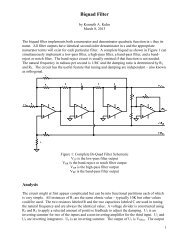
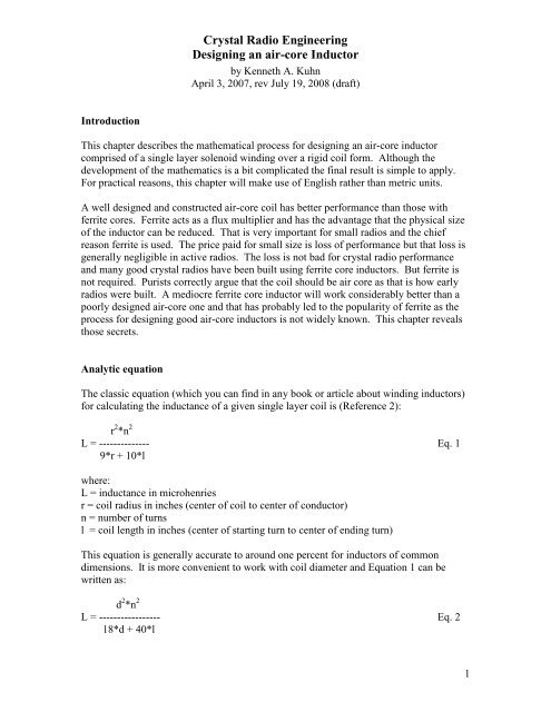
<strong>Crystal</strong> <strong>Radio</strong> <strong>Engineering</strong><strong>Designing</strong> <strong>an</strong> <strong>air</strong>-<strong>core</strong> InductorEstimation of Inductor QAll inductors have <strong>an</strong> equivalent series resist<strong>an</strong>ce loss as discussed earlier <strong>an</strong>d iscomprised of a number of components. We measure the quality factor or Q of theinductor by computing the ratio of inductive react<strong>an</strong>ce at the frequency of interest to theseries loss resist<strong>an</strong>ce as follows:X LQ = ------- Eq. 13RswhereQ is the dimensionles “quality” factor of the inductorX L is the inductive react<strong>an</strong>ce in ohms at the frequency of interestRs is the equivalent series resist<strong>an</strong>ce in ohms at the frequency of interestNote that inductive react<strong>an</strong>ce, X L , is calculated asX L = 2*π*F*LwhereF is the frequency in HzL is the induct<strong>an</strong>ce in henriesThe equivalent series resist<strong>an</strong>ce is the net of ohmic losses including skin effect, dielectriclosses in distributed capacit<strong>an</strong>ce <strong>an</strong>d coil structure, absorption losses by nearbyconducting media, magnetic losses in nearby magnetic media, etc. With care these lossesc<strong>an</strong> be kept small but it takes very little loss to reduce the Q of <strong>an</strong> inductor from 400 to200. The magnitude of Rs c<strong>an</strong> be measured on sophisticated imped<strong>an</strong>ce equipment but itis hard to calculate the effect of all factors. Figure 2 shows <strong>an</strong> estimated value of Q at 1MHz considering typical losses assuming the coil is wound optimally <strong>an</strong>d is not disturbedby nearby lossy materials. Use the figure only as a guideline as your specific results maybe better or worse. The expected Q at 540 kHz will be between about 50 to 70 percent ofwhat is shown <strong>an</strong>d the expected Q at 1.6 MHz will be around 1.2 to 1.5 times that shown.6
<strong>Crystal</strong> <strong>Radio</strong> <strong>Engineering</strong><strong>Designing</strong> <strong>an</strong> <strong>air</strong>-<strong>core</strong> Inductor800700600500Estimated Q of Optimally wound Inductorat 1 MHz#12 <strong>an</strong>d #14 havevinyl insulation#12#16#14#18#20#12 V#14 V#16 M#18 M#20 M#22 M#24 M#26 MQ400#22#24300200#26#16 - #26 aremagnet wire10001.00 10.00 100.00 1000.00Induct<strong>an</strong>ce in microhenriesFigure 2: Estimated Q of InductorThe Q we obtain from Equation 11 is for the unloaded coil (i.e. <strong>an</strong>tenna <strong>an</strong>d crystaldetector not connected). The net loaded Q will typically be signific<strong>an</strong>tly smaller butideally (as discussed in <strong>an</strong>other chapter) would be in the general r<strong>an</strong>ge of one hundred.Thus, we would like to start with <strong>an</strong> unloaded Q of several hundred. As c<strong>an</strong> be seen inFigure 2 the Q of the inductor c<strong>an</strong> be made higher by using larger diameter wire. FromFigure 1 this also me<strong>an</strong>s using a large diameter coil form. This is a very import<strong>an</strong>tconclusion–high Q coils need to be physically large.Type of wireThe only material to consider for the wire is copper. A variety of styles of copper wire isreadily available. The most basic choice is between solid or str<strong>an</strong>ded. Although a varietyof arguments c<strong>an</strong> be made for <strong>an</strong>d against each, in practical terms you will not notice <strong>an</strong>ydifference in perform<strong>an</strong>ce although one or the other may have physical adv<strong>an</strong>tages foryour particular construction method. Avoid wires that are plated as those will havehigher losses since skin-effect will cause most of the conduction to be in the platingwhich has higher resist<strong>an</strong>ce th<strong>an</strong> copper. Avoid wires with rubber or cheap plasticinsulations as dielectric losses will be higher. An exception is silver plated Teflon wire asthat has the best conductivity <strong>an</strong>d the lowest dielectric losses–but it is expensive.For use in low to medium frequency inductors there is a special wire called Litzengrad orjust Litz for short. It is designed to minimize skin-effect losses <strong>an</strong>d is made by7
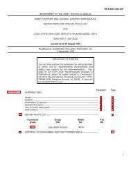
<strong>Crystal</strong> <strong>Radio</strong> <strong>Engineering</strong><strong>Designing</strong> <strong>an</strong> <strong>air</strong>-<strong>core</strong> Inductorassembling m<strong>an</strong>y str<strong>an</strong>ds of enamel insulated magnet wire together to form a wire thathas a large surface area. Litz wire is not easy to find <strong>an</strong>d tends to be expensive. If youare going to use Litz wire then make sure that other losses as previously discussed areminimized. Otherwise Litz wire will make little if <strong>an</strong>y difference <strong>an</strong>d will be wastedeffort <strong>an</strong>d expense.Avoid belief in a variety of myths about skin-effect. Although it is true that skin-effect ismore severe on large diameter conductors, a larger diameter still conducts better th<strong>an</strong> asmaller diameter at <strong>an</strong>y frequency. This c<strong>an</strong> be seen in Figure 3 which shows thefrequency dependence of the resist<strong>an</strong>ce per meter factor of some common wire sizes.AC Resist<strong>an</strong>ce of Copper Wire1.0000000.100000#26#24#22#20#18#16#14#12Ohms per meter0.0100000.0010001,000 10,000 100,000 1,000,000 10,000,000Frequency in HertzFigure 3: AC Resist<strong>an</strong>ce of Copper WireCoil FormsFrom a loss st<strong>an</strong>dpoint <strong>air</strong> is the best coil form material there is. The obvious problem isthat <strong>air</strong> has no structural strength. However, there are methods used by commercialinductor comp<strong>an</strong>ies that employ a minimal structure so that the coil form is around 99percent <strong>air</strong>. M<strong>an</strong>ually, you c<strong>an</strong> achieve the effect by first winding the coil using largediameter solid copper wire (i.e. #18, #16, #14, etc.) on a rigid coil form <strong>an</strong>d then carefullysliding the winding off of the form. The stiff wire will retain the shape <strong>an</strong>d you c<strong>an</strong>easily space the turns to the optimal discussed previously. You will need a few supportsto keep the whole thing from being too loose.8
<strong>Crystal</strong> <strong>Radio</strong> <strong>Engineering</strong><strong>Designing</strong> <strong>an</strong> <strong>air</strong>-<strong>core</strong> InductorA popular coil form is some kind of cardboard tube that you have salvaged from a varietyof sources such as used for paper towels or shipping tubes. These are great if you areusing small diameter wire as small wire will not self support. Plastic pipe is <strong>an</strong>othermaterial you might consider. None of these materials are made with <strong>an</strong>y considerationabout high frequency dielectric losses but because only a small amount of material isused the losses are probably minimal.Wood is a convenient coil form <strong>an</strong>d has low losses if very dry. Common sizes that havebeen used are 2x2, 4x4, or a p<strong>air</strong> of 2x4 combined to make 4x4. Round dowel rods mayalso be used but their diameters are often much less th<strong>an</strong> optimum. When using a squarecoil form there is a logical question about how that affects the induct<strong>an</strong>ce calculations. Asimplistic (but good) <strong>an</strong>swer is to use <strong>an</strong> effective circle diameter that has the same areaas the square form since area is a strong factor in induct<strong>an</strong>ce. Losses with a square formwill be somewhat higher th<strong>an</strong> for a circular form. Rect<strong>an</strong>gular forms (such as a single2x4) have even higher losses in comparison–it takes more wire to encompass a givenarea.Winding the coilCounting turns is a tedious <strong>an</strong>d error prone task. It is much simpler to cut the length ofwire needed <strong>an</strong>d then wind that until finished. The resulting turns count will be veryclose if not exact. Wire is springy <strong>an</strong>d will jump off the form in a t<strong>an</strong>gled mess if notrestrained. Start by securing the wire at one end of the form <strong>an</strong>d have a me<strong>an</strong>s for easily(preferably with one h<strong>an</strong>d) securing the opposite end when you finish. It is tempting touse some kind of adhesive tape <strong>an</strong>d that will work if you are careful <strong>an</strong>d underst<strong>an</strong>d whatyou are doing. The forces will build <strong>an</strong>d the tape may give way which will result in afrustrating mess of t<strong>an</strong>gled wire. Make sure the tape c<strong>an</strong> not slip. A good way to securethe ends is to first drill a hole in the tube at the starting <strong>an</strong>d end points. Then feed thestarting end through the starting hole <strong>an</strong>d bend the wire such that it naturally resiststension <strong>an</strong>d secure the wire with tape. Stuff the loose end length inside the tube so it isout of the way while winding.It is best to wind the coil by h<strong>an</strong>d as the set up for using a lathe is not worth the troublefor a single coil. There are a number of “poor m<strong>an</strong>’s” lathes such as a power drill thathave been used but I do not recommend that as you are more likely to make a mess orcause injury th<strong>an</strong> you are to wind a coil. It only takes a couple of minutes to wind a coilby h<strong>an</strong>d so take the time to think what you are doing. It is import<strong>an</strong>t to keep the windingtight at all times. The wire will spring off if it ever gets loose. You will very likely havesome fractional turn as a result of your calculations. I recommend that you round that tothe nearest integer as it is not worth the trouble of making measurements to stop at aspecific fractional turn.9
References:<strong>Crystal</strong> <strong>Radio</strong> <strong>Engineering</strong><strong>Designing</strong> <strong>an</strong> <strong>air</strong>-<strong>core</strong> Inductor1. Electronic <strong>an</strong>d <strong>Radio</strong> <strong>Engineering</strong>, fourth edition, Frederick Emmons Term<strong>an</strong>,McGraw-Hill Book Comp<strong>an</strong>y, 1955, pages 30–33.2. The <strong>Radio</strong>Amateur’s H<strong>an</strong>dbook, 44 th edition, 1967, The Americ<strong>an</strong> <strong>Radio</strong> RelayLeague, Newington, Conn., page 2610