A Simple Circuit for Measuring Complex Impedance - Ken Kuhn's
A Simple Circuit for Measuring Complex Impedance - Ken Kuhn's
A Simple Circuit for Measuring Complex Impedance - Ken Kuhn's

You also want an ePaper? Increase the reach of your titles
YUMPU automatically turns print PDFs into web optimized ePapers that Google loves.
A <strong>Simple</strong> <strong>Circuit</strong> <strong>for</strong> <strong>Measuring</strong> <strong>Complex</strong> <strong>Impedance</strong><br />
by <strong>Ken</strong>neth A. Kuhn<br />
November 8, 2008, rev. Sept. 16, 2012<br />
Introduction<br />
This article shows a method that can be used to measure complex impedance from audio<br />
frequencies to very high frequencies (VHF – if tight construction practices are followed<br />
and with appropriate diode detectors). All that is required is a known resistance and three<br />
AC voltage measurements – <strong>for</strong> audio frequencies this could be a standard hand-held<br />
DVM. The only disadvantage of this method is that only the phase magnitude and not<br />
the polarity can be measured. In many cases the phase polarity can be inferred from<br />
other known in<strong>for</strong>mation.<br />
An alternative vector method is also shown that does not require a floating voltage<br />
measurement and can resolve phase polarity too. This method is capable of working well<br />
into the UHF range with appropriate equipment.<br />
Mathematical Development<br />
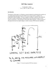
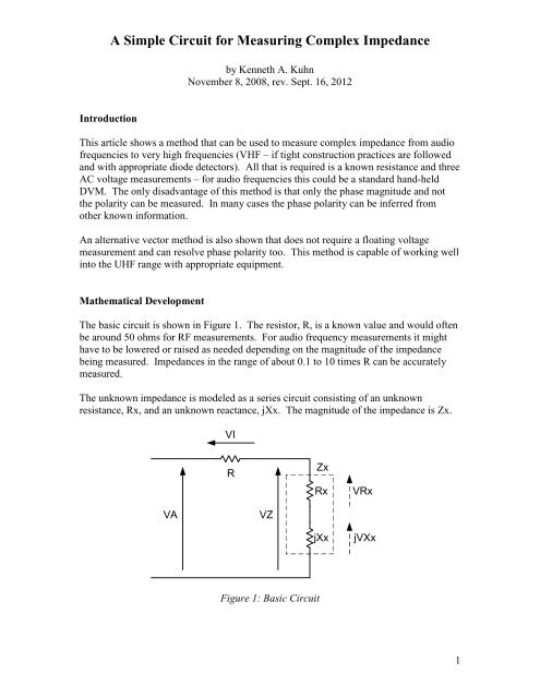
The basic circuit is shown in Figure 1. The resistor, R, is a known value and would often<br />
be around 50 ohms <strong>for</strong> RF measurements. For audio frequency measurements it might<br />
have to be lowered or raised as needed depending on the magnitude of the impedance<br />
being measured. <strong>Impedance</strong>s in the range of about 0.1 to 10 times R can be accurately<br />
measured.<br />
The unknown impedance is modeled as a series circuit consisting of an unknown<br />
resistance, Rx, and an unknown reactance, jXx. The magnitude of the impedance is Zx.<br />
VI<br />
R<br />
Zx<br />
Rx<br />
VRx<br />
VA<br />
VZ<br />
jXx<br />
jVXx<br />
Figure 1: Basic <strong>Circuit</strong><br />
1
A <strong>Simple</strong> <strong>Circuit</strong> <strong>for</strong> <strong>Measuring</strong> <strong>Complex</strong> <strong>Impedance</strong><br />
The three voltages that are measured are:<br />
1. VA which is the applied voltage<br />
2. VI which is the voltage across the known resistor and related to the current<br />
3. VZ which is the voltage across the unknown impedance<br />
Although only the magnitudes of these voltages are known, these are actually vectors as<br />
shown in Figure 2 which applies to both methods. The angle, θ, is unknown at the<br />
moment but can be determined. The vector voltages across the internal resistance and<br />
reactance of the impedance are shown <strong>for</strong> reference but there is no way to directly<br />
measure these. The angle, Φ, is used in the alternative vector method discuss later.<br />
θ<br />
VI<br />
VRx<br />
VA<br />
VZ<br />
jVXx<br />
Φ<br />
Figure 2: Vector Diagram<br />
Ground<br />
The law of cosines is used to calculate the cosine of the angle, θ.<br />
VA 2 + VI 2 – VZ 2<br />
cos(θ) = ------------------------ Eq. 1<br />
2 * VA * VI<br />
With real measurements there are two things that can go wrong in Equation 1 that need to<br />
be artificially corrected. As a reality check the result of Eq. 1 should be between 0 and<br />
1.00 but subtle measurement errors can skew that as follows.<br />
1. Because of small measurement errors it is possible that cos(θ) will be negative –<br />
probably only by a small amount. If that happens then use 0.00 as this means that<br />
the magnitude of the unknown impedance is purely reactive – in theory this<br />
2
A <strong>Simple</strong> <strong>Circuit</strong> <strong>for</strong> <strong>Measuring</strong> <strong>Complex</strong> <strong>Impedance</strong><br />
should never exactly go to zero as the measurement R will cause a small angle<br />
shift from 90 degrees. Repeat the measurement using a larger R.<br />
2. It is possible that cos(θ) will numerically explode if VI is a very small value –<br />
particularly zero. This can happen if the impedance is very large in comparison to<br />
R. In such a case the proper thing to do is to substitute 1.00 <strong>for</strong> the result but the<br />
accuracy of the subsequent calculations is going to be very poor. The better<br />
solution is to use a larger R so that a definitely measureable voltage across it can<br />
be made.<br />
The magnitude of the total impedance (including R) can be calculated as:<br />
Za = R * VA / VI Eq. 2<br />
We note from Figure 1 that the sum of R and Rx can be found by:<br />
R + Rx = Za * cos(θ) Eq. 3<br />
Thus, we can solve <strong>for</strong> Rx by:<br />
Rx = Za * cos(θ) – R Eq. 4<br />
Considering possible measurement errors it is conceivable that Rx could compute to be<br />
negative which is not likely to be the real situation. The proper thing to do if that<br />
happens is to take Rx to be zero. The impedance is purely reactive.<br />
The magnitude of the unknown impedance can be calculated as:<br />
Zx = R * VZ / VI Eq. 5<br />
The magnitude of the unknown reactance can be calculated as:<br />
Xx = sqrt(Zx 2 – Rx 2 ) Eq. 6<br />
Considering possible measurement errors it is conceivable that the square root of a<br />
negative number might occur. If that happens then Xx should be taken to be zero.<br />
Example<br />
The “unknown” impedance consists of a 30 ohm resistor in series with a 60 ohm<br />
reactance which combine to <strong>for</strong>m a 67 ohm complex impedance. The measurement<br />
resistor is 50 ohms. The applied voltage, VA, is 1 Vrms. The measured VI is 0.50 Vrms<br />
and the measured VZ is 0.67 Vrms. The cosine of theta computes to be 0.800. The<br />
impedance computes to be 67 ohms, Rx computes to be 30 ohms, and jXx computes to be<br />
j60 ohms. Thus, the method has been shown to work.<br />
3
A <strong>Simple</strong> <strong>Circuit</strong> <strong>for</strong> <strong>Measuring</strong> <strong>Complex</strong> <strong>Impedance</strong><br />
Parallel <strong>Impedance</strong><br />
The methods used in this article determine the series resistance and reactance.<br />
Sometimes the equivalent parallel impedance of a resistance and reactance may be<br />
needed. All that is required is a mathematical series to parallel conversion as follows.<br />
The concept is to relate the real and imaginary conductance of the parallel network to the<br />
conductance of the series network. The numerator and denominator of the series network<br />
conductance is multiplied by the complex conjugate of the denominator to put the result<br />
in normal <strong>for</strong>m.<br />
1 1 1 Rs - jXs<br />
----- + ----- = -------------- = -------------- Eq. 7<br />
Rp jXp Rs + jXs Rs 2 + Xs 2<br />
where Rs and Xs are the series values and Rp and Xp are the parallel values.<br />
By equating the real part we have the equivalent parallel resistance and by equating the<br />
imaginary part we have the equivalent parallel reactance:<br />
Rs 2 + Xs 2<br />
Rp = -------------- Eq. 8<br />
Rs<br />
Rs 2 + Xs 2<br />
Xp = -------------- Eq. 9<br />
Xs<br />
Note that since the phase polarity of Xs was not known then the phase polarity of Xp is<br />
also not known but is the same sign. The previous example converts to a 150 ohm<br />
resistor in parallel with j75 ohms.<br />
Determining the phase polarity<br />
The sign of the reactance matches that of the angle, θ. This means that an inductive<br />
reactance will have positive polarity and capacitive reactance will have negative polarity.<br />
If a small capacitive reactance is added in series with the impedance and the magnitude<br />
of the reactance increases then the unknown reactance is capacitive. It would be<br />
inductive if the magnitude of reactance decreased. A similar concept can be achieved by<br />
adding a small inductive reactance with the impedance. The impedance would be<br />
inductive if the reactance magnitude increased and capacitive if the reactance magnitude<br />
decreased. The additional series reactance should a fraction of the load reactance.<br />
If the unknown impedance is a simple structure of resistance and reactance then the phase<br />
polarity can be determined by noting the change in the reactance magnitude as the<br />
applied frequency is changed. The reactance is inductive if an increase in frequency<br />
4
A <strong>Simple</strong> <strong>Circuit</strong> <strong>for</strong> <strong>Measuring</strong> <strong>Complex</strong> <strong>Impedance</strong><br />
causes an increase in the reactance magnitude and capacitive if an increase in frequency<br />
causes a decrease in the reactance magnitude. This method can give confusing results if<br />
the unknown impedance is a complex network structure involving either numerous<br />
reactive components or is a transmission line or antenna or similar structure that has<br />
wilding varying reactance with frequency.<br />
Another method involves measuring VI using a time delayed version of VA. The delay<br />
should only be just enough <strong>for</strong> the measurement. This method is similar to the first<br />
method of adding a series reactance. If the VI term decreases then the impedance is<br />
capacitive.<br />
Vector Method Using Oscilloscope or Vector Voltmeter<br />
<strong>Measuring</strong> VI requires a floating meter which can have issues, particularly at high<br />
frequencies. The setup in Figure 3 can be used to measure VA, VZ, and the angle, Φ,<br />
between them – the phase of VZ relative to VA. A vector voltmeter typically provides a<br />
direct measure of the phase angle. Using an oscilloscope the peak-peak amplitude of VA<br />
and VZ can be measured and the phase angle, Φ, (between the voltages, not the angle of<br />
the impedance) can be determined by triggering the scope on VA and measuring the time<br />
difference between the zero crossings. The time difference can be related to the phase<br />
angle using Equation 10.<br />
Φ = (time_difference in seconds) * 360 * frequency in Hz Eq. 10<br />
Using the law of cosines and referring to Figure 1 the magnitude of VI can be calculated<br />
as:<br />
VI = sqrt(VA 2 + VZ 2 – 2*VA*VZ*cos(Φ)) Eq. 11<br />
Then equations 2 through 6 can be used to determine Rx and Xx. With this approach the<br />
polarity of Φ is known. The polarity of Xx is set to be the same as the polarity of Φ<br />
noting that the squaring and square root process destroys sign in<strong>for</strong>mation.<br />
Vector voltmeters often provide the ratio of the channel 2 voltage to the channel 1<br />
voltage which in this case would be (VZ/VA). Then we can calculate<br />
(VI/VA) = sqrt(1 + (VZ/VA) 2 – 2*(VZ/VA)*cos(Φ)) Eq. 12<br />
We then substitute this into a modified version of Equation 1.<br />
1 + (VI/VA) 2 – (VZ/VA) 2<br />
cos(θ) = ---------------------------------- Eq. 13<br />
2 * (VI/VA)<br />
5
A <strong>Simple</strong> <strong>Circuit</strong> <strong>for</strong> <strong>Measuring</strong> <strong>Complex</strong> <strong>Impedance</strong><br />
If the ratio is given in dB then we first calculate<br />
(VZ/VA) = 10 (dB/20) Eq. 14<br />
and then substitute the result of Equation 14 into Equation 12.<br />
Figure 3: Vector method<br />
An extension to this method that is very applicable at high frequencies uses a vector<br />
voltmeter and a power splitter as shown in Figure 4. Note that this is a pure bridge with<br />
the only difference in that the scope or meter measures the voltage with respect to ground<br />
of each side of the bridge rather than the difficult to measure floating voltage between the<br />
arms. The math is identical <strong>for</strong> this method except that the (VZ/VA) value must be<br />
divided by 2 since the math is derived using Figure 3 and VZ is the ratio to one-half of<br />
the applied voltage.<br />
Tee<br />
CH2<br />
Power<br />
Splitter<br />
R<br />
R<br />
Oscilloscope or<br />
Vector Voltmeter<br />
Z<br />
VZ<br />
Applied<br />
Voltage<br />
CH1<br />
VA<br />
Tee<br />
R<br />
Termination<br />
Figure 4: Vector Voltmeter using power splitter<br />
6
A <strong>Simple</strong> <strong>Circuit</strong> <strong>for</strong> <strong>Measuring</strong> <strong>Complex</strong> <strong>Impedance</strong><br />
Some advanced thoughts on the vector math<br />
If the vector voltmeter implementation of Figure 3 is used then the (VZ/VA) is as be<strong>for</strong>e.<br />
That value should be halved if using the power splitter method shown in Figure 4.<br />
It is convenient to merge Equations 11 and 12 so that only the ratio (VZ/VA) is used.<br />
1 + [1 + (VZ/VA) 2 – 2*(VZ/VA)*cos(Φ)] – (VZ/VA) 2<br />
cos(θ) = ------------------------------------------------------------------ Eq. 15<br />
2*sqrt[1 + VZ/VA) 2 – 2*(VZ/VA)*cos(Φ)]<br />
which simplifies to<br />
1 – (VZ/VA)* cos(Φ)<br />
cos(θ) = ----------------------------------------------------- Eq. 16<br />
sqrt[1 + (VZ/VA) 2 – 2*(VZ/VA)*cos(Φ)]<br />
Equation 5 was<br />
Zx = R * VZ / VI (Eq. 5)<br />
We note that<br />
(VZ/VA)<br />
(VZ/VA)<br />
VZ/VI = ------------- = ---------------------------------------------------- Eq. 17<br />
(VI/VA) sqrt[1 + (VZ/VA) 2 – 2*(VZ/VA)*cos(Φ)]<br />
There<strong>for</strong>e<br />
(VZ/VA)<br />
Zx = R * ---------------------------------------------------- Eq. 18<br />
sqrt[1 + (VZ/VA) 2 – 2*(VZ/VA)*cos(Φ)]<br />
The total impedance including the series R on the load side of the bridge is ZA.<br />
R<br />
ZA = R / (VI/VA) = ---------------------------------------------------- Eq. 19<br />
sqrt[1 + (VZ/VA) 2 – 2*(VZ/VA)*cos(Φ)]<br />
The real part of the unknown impedance is then<br />
Rx = ZA*cos(θ) – R (Eq. 4)<br />
7
A <strong>Simple</strong> <strong>Circuit</strong> <strong>for</strong> <strong>Measuring</strong> <strong>Complex</strong> <strong>Impedance</strong><br />
By combining Equations 4 and 16 we have<br />
R * (1 – (VZ/VA) * cos(Φ))<br />
Rx = ZA*cos(θ) = ---------------------------------------------- - R Eq. 20<br />
1 + (VZ/VA) 2 – 2*(VZ/VA)*cos(Φ)<br />
which simplifies to<br />
(VZ/VA) – cos(Φ)<br />
Rx = R * ------------------------------------------------ Eq. 21<br />
2*cos(Φ) - (VZ/VA) – [1 / (VZ/VA)]<br />
The reactance of the unknown impedance is calculated as be<strong>for</strong>e as<br />
Xx = sqrt(Zx 2 – Rx 2 ) (Eq. 6)<br />
and <strong>for</strong>cing the reactance to be zero should the square root of a negative number occur.<br />
The angle of the unknown impedance is found by taking the arctangent of the ratio of the<br />
reactive impedance to the resistive impedance.<br />
The following is a fragment of c language code that shows the processing including<br />
handling of numerical issues that can arise in measured data.<br />
/* c fragment to process vector voltmeter data */<br />
#define SERIES_RESISTOR 1<br />
#define POWER_SPLITTER 2<br />
#define DEG2RAD (3.141592654 / 180.0)<br />
#define SMALL 1E-20<br />
/* Input Variables to c fragment */<br />
double vv_voltage_ratio; /*(VZ/VA)from vector voltmeter */<br />
double vv_angle; /* angle in degrees between VZ and VA */<br />
double rsystem; /* resistance of series resistor or power divider */<br />
int method; /* either SERIES_RESISTOR or POWER_SPLITTER see #defines */<br />
/* Computed outputs from c fragment */<br />
double vv_angle_cosine; /* cosine of vector voltmeter angle */<br />
double impedance_magnitude; /* in ohms */<br />
double impedance_angle; /* in degrees */<br />
double impedance_rseries; /* in ohms */<br />
double impedance_xseries; /* in ohms */<br />
double temp; /* temporary variable */<br />
{<br />
if(method = POWER_SPLITTER)<br />
vv_voltage_ratio /= 2.0;<br />
vv_angle_cosine = cos(vv_angle*DEG2RAD);<br />
8
A <strong>Simple</strong> <strong>Circuit</strong> <strong>for</strong> <strong>Measuring</strong> <strong>Complex</strong> <strong>Impedance</strong><br />
temp = 1.0<br />
+ vv_voltage_ratio * vv_voltage_ratio<br />
- 2.0 * vv_voltage_ratio * vv_angle_cosine;<br />
if(temp < SMALL)<br />
temp = SMALL; /* This handles negative and too small positive */<br />
temp = sqrt(temp);<br />
impedance_magnitude = rsystem * vv_voltage_ratio / temp;<br />
impedance_rseries = rsystem * (vv_voltage_ratio – vv_angle_cosine))<br />
/ (2.0 * vv_angle_cosine) – vv_voltage_ratio<br />
-(1.0 / vv_voltage_ratio));<br />
temp = impedance_magnitude^2 –impedance_rseries^2;<br />
if(temp < 0.0)<br />
temp = 0.0;<br />
impedance_xseries = sqrt(temp);<br />
if(vv_angle < 0.0)<br />
impedance_xseries = -impedance_xseries;<br />
impedance_angle = atan2(impedance_rseries, impedance_xseries)<br />
/ DEG2RAD;<br />
}<br />
9