Aspire cooker service procedures - Swift Owners Club
Aspire cooker service procedures - Swift Owners Club
Aspire cooker service procedures - Swift Owners Club

You also want an ePaper? Increase the reach of your titles
YUMPU automatically turns print PDFs into web optimized ePapers that Google loves.
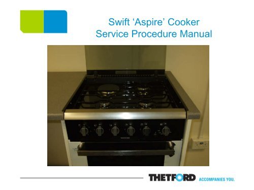
<strong>Swift</strong> ‘<strong>Aspire</strong>’ Cooker<br />
Service Procedure Manual
Contents page<br />
Slide 1: Front Page<br />
Slide 2: Contents Page<br />
Slides 3 & 4: The Fascia<br />
Slides 5 – 7: The Hob Pressing<br />
Slides 8 – 10: The Thermocouple<br />
Slides 11 & 12: The Ignition Electrode<br />
Slide 13 – 15: The Shut Off Mechanism<br />
Slides 16 & 17: The 12v Spark Generator<br />
Slide 18: Hotplate, Switch and 230v Generator Wiring Drawing<br />
Slides 19 – 21: The 12v Fans<br />
Slides 22 – 25: The Grill Burner<br />
Slides: 26 & 27: The Hob/Grill Gas Burner Valve<br />
Slides 28 – 30: The Thermostatic Valve<br />
Slides 31 – 33: Dealer Time Allowances
The Fascia<br />
Remove control knobs<br />
Remove 2 x 16mm locking nuts<br />
and fibre washers<br />
Remove 2 x screws below electric<br />
hotplate switch and below oven<br />
valve<br />
Remove 2 x screws from profile
The Fascia, continued<br />
Lift and pull profile forward in<br />
order to remove fascia from<br />
pressing<br />
Remove 2 spade connectors<br />
from ignition switch (these are<br />
not polarity sensitive)
The Hob Pressing<br />
Remove pan support<br />
Remove 4 hob side trim screws<br />
(PZ2 screwdriver)<br />
Remove screws on burner caps<br />
(PZ1 screwdriver)<br />
Remove burner cup fixing studs<br />
(5mm socket)
The Hob Pressing, continued<br />
Loosen grub screws on hinges<br />
and lift out glass lid<br />
Loosen 4 dome headed screws<br />
on hinges<br />
Remove 2 screws on rear trim<br />
that secure pressing
Lift pressing from the front and<br />
remove cables and earth<br />
connection from hotplate<br />
(please note cable<br />
configuration – see diagram)<br />
The Hob Pressing, continued<br />
Slide back of pressing from<br />
under rear trim<br />
Reverse process when<br />
replacing hob panel with new.
Disconnect and remove <strong>cooker</strong><br />
from its housing.<br />
The Thermocouple<br />
Lift up the hob pressing to gain<br />
access to the components below.<br />
Both the oven and grill have earth<br />
straps coming attached to the<br />
thermocouples. Ensure that the<br />
earth strap is fitted/not loose before<br />
removing the fixing screw/locking<br />
nut holding the thermocouple to the<br />
respective burner. Remove the<br />
spade fitting from the valve and<br />
replace.
The Thermocouple, continued<br />
There are two thermocouples<br />
for the hob burners. One,<br />
which is black, goes from the<br />
valve to the shut off mechanism<br />
and the second, which is<br />
copper, goes from the burner to<br />
the shut off mechanism.<br />
Trace the relevant<br />
thermocouple back to the shut<br />
off mechanism and pull off the<br />
spade fitting. If the<br />
thermocouple is for the gas<br />
valve pull off the spade fitting<br />
and replace.
The Thermocouple, continued<br />
If the thermocouple is from the<br />
burner to the shut off<br />
mechanism. Trace back to the<br />
shut off valve and pull off the<br />
spade fitting. Use an 8mm<br />
spanner to remove the locking<br />
nut holding the thermocouple<br />
probe to the burner cup.
Disconnect and remove the<br />
<strong>cooker</strong> from its housing.<br />
The Ignition Electrode<br />
Lift the hob pressing and check<br />
the connection of the relevant<br />
electrode on the 12v generator.<br />
If the electrode is faulty then<br />
pull the spade fitting off the<br />
terminal point. The electrodes<br />
for the oven and grill are<br />
secured by a single self tapping<br />
screw. Remove this and gently<br />
pull the electrode through the<br />
cavity box and replace.
The Electrodes for the hob<br />
burners are retained on the<br />
burner cup by a silver<br />
‘crocodile’ clip. Squeeze and<br />
pull the clip off and then lift the<br />
probe out of the burner cup.<br />
The Ignition Electrode, continued
The Shut Off Mechanism<br />
Disconnect and remove <strong>cooker</strong><br />
from the housing.<br />
Remove the 4 x screws<br />
retaining the back plate to the<br />
<strong>cooker</strong>. This will allow you<br />
access to the shut off<br />
mechanism bracket.<br />
Remove the two silver screws<br />
noting which holes are used on<br />
the metal bracket.
The Shut Off Mechanism, continued<br />
The shut off’s wiring is as<br />
follows; 1. Hotplate (2 x Red<br />
wires), 2. Front left hob burner,<br />
3. Front right burner, 4. Rear<br />
right burner. Trace the black<br />
thermocouples back to their<br />
relevant burner valves. It is<br />
imperative to ensure that both<br />
types of thermocouples for<br />
each burner correspond on the<br />
shut off terminals. If both are<br />
not correctly matched then at<br />
least two hob burners will not<br />
function.
The Shut Off Mechanism, continued<br />
Pull off all spade fittings from all<br />
four terminals to remove the<br />
shut off mechanism from the<br />
<strong>cooker</strong>. Take care not to<br />
misplace the thin metal<br />
pin/barrel from the glass lid<br />
hinge.
Disconnect and remove <strong>cooker</strong><br />
from its housing.<br />
The 12v Spark Generator<br />
Remove the 4 x screws holding the<br />
rear galvanized plate to the <strong>cooker</strong>.<br />
The 12v spark generator is clipped<br />
onto this plate.<br />
To remove the generator gently<br />
push down on the generator and<br />
pull away from the galvanized plate<br />
until the top clip is free from the<br />
box. Lift bottom clip to remove the<br />
generator.
The 12v Spark Generator, continued<br />
The wiring on the 12v generator is<br />
as follows; Terminal 1. Purple 12v<br />
ignition wire. Terminal 2. Black<br />
negative wires for the two fans and<br />
12v ignition. Terminal A. Earth<br />
strap. The remaining terminals B<br />
to F are for the three hob burner,<br />
grill and oven electrodes. These<br />
five wires can go on any of these<br />
terminal points.<br />
2 1<br />
A<br />
Pull off all spade fittings from<br />
terminals to remove the generator<br />
completely.
Hotplate, Switch and 230v Generator
The 12v Fans<br />
Disconnect and remove <strong>cooker</strong><br />
from its housing.<br />
Remove the silver screws both left<br />
and right holding the galvanized<br />
plate to the <strong>cooker</strong>.<br />
Cut both positive and negative<br />
wires as close as possible to the<br />
crimps. See the wiring diagram on<br />
the next slide.
The 12v Fans, continued
The 12v Fans, continued<br />
Using an adjustable or 7mm<br />
spanner release both the top and<br />
bottom nuts and shake proof<br />
washers whilst you hold the screw<br />
still with a stubby screwdriver or<br />
your fingers.<br />
Replace fan or fans and connect<br />
both sets of positive and negative<br />
wires together using crimps. Be<br />
sure to correspond the wires to<br />
ensure correct polarity. The fan<br />
side that has the label on should<br />
face inward towards the appliance.
The Grill Burner<br />
Disconnect and remove <strong>cooker</strong>.<br />
Remove pressing, lid, side<br />
trims and unscrew shut off from<br />
hinge. Remove screws on the<br />
rear galvanized box.<br />
Unscrew and remove both<br />
galvanized side sheets.
The Grill Burner, continued<br />
Unscrew and slowly retract the flue<br />
diverter box housing the two 12v<br />
fans.<br />
Take care not to trap or snag any<br />
part of the wiring looms or to tear<br />
the grill box insulation cover.
The Grill Burner, continued<br />
Using a stanley knife or similar<br />
cut through the silver insulation<br />
tape holding the insulation<br />
cover to the grill box. Gently<br />
pull the insulation cover through<br />
the <strong>cooker</strong> and clear the top of<br />
the grill box of any ‘debris’.<br />
Using a thin flat headed<br />
screwdriver or similar carefully<br />
prize off the two starlock<br />
washers holding the grill burner<br />
spigots to the box roof.
The Grill Burner, continued<br />
Once the starlock washers<br />
have been removed the grill<br />
burner tube and attached mesh<br />
can then be lowered and from<br />
the grill box roof and removed<br />
from the <strong>cooker</strong>.<br />
It is advisable that new starlock<br />
washers are used when refitting<br />
or replacing the grill burner.
The Hob/Grill Gas Burner Valve<br />
It is advisable to remove the<br />
appliance when carrying out<br />
‘internal’ work so as to avoid<br />
any damage. Remove the hob<br />
pressing.<br />
Unscrew the bridging piece<br />
holding the burner valve to the<br />
gas rail or manifold.<br />
Pull off the push-fit<br />
thermocouple.
The Hob/Grill Gas Burner Valve, continued<br />
Using a 10mm spanner<br />
unscrew the nut holding the<br />
burner feed pipe to the burner<br />
valve. The burner valve can<br />
then be removed from the gas<br />
rail or manifold.
The Thermostatic Valve<br />
As with the ‘Hob/Grill Gas<br />
Burner Valve’, remove all<br />
necessary screws and parts to<br />
enable access to the gas rail or<br />
manifold.<br />
You will need a PZ2 size<br />
screwdriver to remove the<br />
screws holding the thermostat<br />
mounting bracket to the<br />
thermostat and the fascia<br />
mounting plate. Start by<br />
removing the screws at the<br />
back.
The Thermostatc Valve, continued<br />
A 13mm spanner will lossen the<br />
nut holding the oven burner feed<br />
pipe to the thermostat valve.<br />
Use a 17mm spanner or adjustable<br />
to loosen nut holding thermostat<br />
valve to the gas rail or manifold.
The Thermostatic Valve, continued<br />
Drop down the oven door and,<br />
using the PZ2 screwdriver, slacken<br />
up the two copper ‘P-clips’ located<br />
a third of the way down on the right<br />
hand oven cavity wall.<br />
Pull the capillary tube and phial<br />
(sensor probe) through the ‘P-clips’<br />
and through the back of the oven<br />
cavity.<br />
Reverse the entire process when<br />
replacing the thermostat valve.