

SP-2 and SP-5 User and installation manual - MGL Avionics
SP-2 and SP-5 User and installation manual - MGL Avionics
SP-2 and SP-5 User and installation manual - MGL Avionics

Create successful ePaper yourself
Turn your PDF publications into a flip-book with our unique Google optimized e-Paper software.
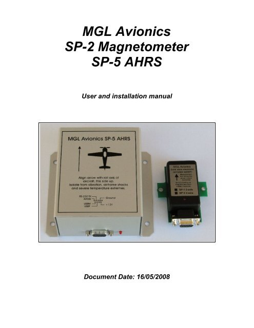
<strong>MGL</strong> <strong>Avionics</strong><br />
<strong>SP</strong>-2 Magnetometer<br />
<strong>SP</strong>-5 AHRS<br />
<strong>User</strong> <strong>and</strong> <strong>installation</strong> <strong>manual</strong><br />
Document Date: 16/05/2008
About this document<br />
This document describes <strong>installation</strong> <strong>and</strong> usage for the <strong>SP</strong>-2 magnetometer (electronic<br />
compass) <strong>and</strong> <strong>SP</strong>-5 AHRS (Attitude Heading Reference System) for connection to <strong>MGL</strong><br />
<strong>Avionics</strong> flight instrumentation systems.<br />
Connectivity<br />
These units are designed to be connected to the AV-1 Smart Single, AV-1 Infinity, AV-2 Maxi<br />
Single, Ultra H, Ultra HXL, Enigma, Voyager <strong>and</strong> Odyssey instruments.<br />
Further to this, these units may be used with compatible systems made by third parties.<br />
Please consult relevant documentation with your third party system.<br />
Interface<br />
The <strong>SP</strong>-2 <strong>and</strong> <strong>SP</strong>-5 units make use of the <strong>MGL</strong> <strong>Avionics</strong> propriety Airtalk link which is based<br />
on ordinary RCA audio or video cables for ease of <strong>installation</strong>.<br />
Airtalk is a low speed, low EMI (electrical noise) connection intended to be used with <strong>MGL</strong><br />
<strong>Avionics</strong> equipment data links containing modest data rates.<br />
Airtalk is a multi master link allowing several items to share a single connection. In particular,<br />
within context of this document, it is often required to share a single Airtalk link between both<br />
<strong>SP</strong>-2 <strong>and</strong> <strong>SP</strong>-5 units to form a full AHRS system.<br />
The <strong>SP</strong>-2 magnetometer<br />
The <strong>SP</strong>-2 magnetometer is a three axis, tilt compensated electronic compass system. It<br />
outputs magnetic heading information.<br />
Tilt compensation is performed by deriving the attitude of the <strong>SP</strong>-2 sensor using on-board<br />
accelerometers which are used to vector the direction of gravity. The magnetic field is<br />
measured using three magnetometers which are mounted perpendicular to each other<br />
resulting in three magnetic force vectors.
Using three magnetic force vectors <strong>and</strong> knowledge of attitude allows calculation of magnetic<br />
heading even if the <strong>SP</strong>-2 is not horizontal.<br />
There are limitations to this method. During turns the accelerometers will give incorrect<br />
indications due to centrifugal forces acting on the <strong>SP</strong>-2. This will result in incorrect heading<br />
readouts during the turn. However, compared to an ordinary mechanical compass, the<br />
heading is still usable as it tends to show heading changes in the correct manner (even if<br />
heading if not 100% correct) <strong>and</strong> will allow you to fall out of the turn on the intended heading.<br />
The moment you are flying straight, the heading is instantly correct. This is in contrast to a<br />
normal mechanical compass which tends to over or under swing <strong>and</strong> may need considerable<br />
settling time.<br />
As alternative, if you have a <strong>SP</strong>-5 AHRS connected to the same Airtalk bus as the <strong>SP</strong>-2, you<br />
can set the <strong>SP</strong>-2 to “gyro mode” for attitude data. This would be done in your connected<br />
instrument as part of the compass mode setup. <strong>MGL</strong> equipment refers to this as 3DG mode<br />
(3D gyro vs 3D accelerometer mode as 3DA).<br />
If your <strong>SP</strong>-2 is set to gyro mode <strong>and</strong> horizon data is being received, your <strong>SP</strong>-2 will use the<br />
gyro derived horizon rather than the built in accelerometers for tilt compensation. In this case,<br />
heading is correct even during turns. Be aware that in this mode, should your horizon be<br />
incorrect due to exceeding maximum rate of turns or prolonged maneuvering, your heading<br />
will be incorrect too.<br />
We recommend that for normal aircraft operations you leave the <strong>SP</strong>-2 in normal<br />
accelerometer mode (3DA). In this case the <strong>SP</strong>-2 heading can be used even if the horizon is<br />
unreliable. With many aircraft, attitude can be maintained by relying on compass heading <strong>and</strong><br />
slip indication if no valid horizon information is available.<br />
<strong>SP</strong>-2 Installation<br />
The most critical decision to make before installing your <strong>SP</strong>-2 is to decide on a good location<br />
inside your aircraft. Many aircraft, in particular those based on steel structures very significant<br />
magnetic deviation is present in many locations. Such locations are unsuitable.<br />
We recommend that you do a basic survey using a small h<strong>and</strong> held hiking compass inside<br />
your aircraft to help locate areas of high deviation. Note that you must orientate your aircraft<br />
on several headings <strong>and</strong> repeat the process to find a good location – doing this on just a<br />
single heading is seldom successful.<br />
Your aim is to find a location that will give you a heading error of less than 10º on any heading<br />
in normal flight attitude. Only in this case will you be able to use the built in compensation <strong>and</strong><br />
alignment functions to eliminate the remaining errors properly. If you start with a large error,<br />
perhaps 20º or larger, you have little chance of calibrating this error out. Rather find a better<br />
location.<br />
In extreme cases, consider locating the <strong>SP</strong>-2 outside the fuselage, perhaps in a wing tip. The<br />
wires running to the <strong>SP</strong>-2 can be lengthened if required.<br />
When attempting to find a suitable location for your <strong>SP</strong>-2, be aware of the following:<br />
Avoid any areas that have iron based metals in close or relatively close proximity.<br />
Avoid proximity of instrumentation containing magnets (many electrical “needle” based<br />
instruments contain magnets).
Avoid proximity to autopilot servo motors, electric fuel pumps <strong>and</strong> other electric motors.<br />
Avoid proximity to any wiring containing electrical supply currents (the currents will<br />
cause a magnetic field to build up around the cable).<br />
Avoid any proximity to ferro metallic fasteners such as nuts <strong>and</strong> bolts.<br />
Be suspicious of stainless steel – although non magnetic in its highest grade form, many<br />
grades will be magnetic as they are not pure. Test with a small magnet if unsure. If the<br />
magnet sticks, it is a problem.<br />
Be aware that the Earth magnetic field is very weak <strong>and</strong> is easily disturbed by any of the<br />
above items. If you want to experiment to find out just how easy it can be disturbed, move a<br />
screwdriver close to the <strong>SP</strong>-2 (once it is connected <strong>and</strong> operating) <strong>and</strong> observe the effect on<br />
your heading. You may be surprised!<br />
The <strong>SP</strong>-2 will in all cases faithfully show the direction of the magnetic field passing through it,<br />
even if this is not the direction of the Earth magnetic field at your location.<br />
The <strong>SP</strong>-2 is normally connected to a 12V or 24V DC power system. Power consumption is<br />
modest at less than 50mA. Power supplies must be protected from transient events that raise<br />
voltage levels above 35V (these events can be caused by solenoids <strong>and</strong> starter motors <strong>and</strong><br />
other electrical gear). Exceeding a voltage of 35V positive or 100V negative will destroy the<br />
<strong>SP</strong>-2.<br />
Mounting the <strong>SP</strong>-2<br />
Mount the <strong>SP</strong>-2 in a position that is not affected by ferro magnetic metals including nuts <strong>and</strong><br />
bolts. Mount the <strong>SP</strong>-2 using plastic, brass or aluminum fasteners. As alternative, consider<br />
industrial quick release fasteners such as self-adhesive Velcro or similar systems.<br />
Try <strong>and</strong> mount the <strong>SP</strong>-2 in such a way that it will be horizontal or close to horizontal during<br />
normal cruise flight. The internal tilt compensation is effective to about 60º pitch <strong>and</strong> bank but<br />
additional errors can still be introduced. These however are very negligible if only small<br />
amounts of tilt are present.<br />
<strong>SP</strong>-2 deviation compensation<br />
It is normal to have small amounts of deviation in an aircraft compass <strong>installation</strong>. Deviation is<br />
caused by nearby hard or soft iron <strong>and</strong> other effects.<br />
With a traditional mechanical compass small magnets are placed or rotated in close proximity<br />
to the compass to correct for most of the deviation. It is quite possible to do the same with an<br />
electronic compass but there is another way. Objects causing deviation tend to modify the<br />
strength of the magnetic field in their proximity. This can be used to help compensate for the<br />
deviation in many cases.<br />
Consult your display device's <strong>manual</strong> on how to enter <strong>and</strong> leave deviation compensation<br />
mode.<br />
Warning: Only proceed with deviation compensation if your deviation is relatively small<br />
(perhaps a maximum of 10º). Large deviation can seldom be corrected significantly this way –<br />
your only option is to either remove the offending source (such as a iron bolt perhaps) or to<br />
find a better location for your <strong>SP</strong>-2.
Deviation compensation consists of entering deviation compensation mode <strong>and</strong> rotating your<br />
aircraft through at least one full 360 turn on the ground. The <strong>SP</strong>-2 must during this procedure<br />
remain horizontal to the Earths surface. If you have a tail dragger, lift the tail while you<br />
perform this maneuver.<br />
Once the turn is completed you need to end the deviation compensation procedure. It is also<br />
possible to clear any deviation compensation <strong>and</strong> return the unit to factory calibration.<br />
Note: Be aware that many concrete reinforced aircraft aprons or runways may contain<br />
significant amounts of iron which may make it impossible to perform any meaningful deviation<br />
compensation on these surfaces. Also, do not attempt to calibrate your compass inside a<br />
hanger that contains significant amounts of iron based metals as part of the construction.<br />
<strong>SP</strong>-2 alignment<br />
Your <strong>SP</strong>-2 includes a second method to calibrate directly to the four major cardinal headings<br />
North, South, West <strong>and</strong> East. Consult your display instruments <strong>manual</strong> for details on how to<br />
use this function.<br />
The procedure requires that you have exact transits to the cardinal headings that you can use<br />
as reference. Note that you need magnetic headings. Use a small survey or good hiking<br />
compass to find suitable transits.<br />
This calibration is intended to be performed after normal deviation compensation to eliminate<br />
remaining deviation or to be used on its own if you only need to correct for very small<br />
deviation <strong>and</strong> the normal procedure does not fully compensate for any errors.<br />
Align your aircraft with the cardinal heading you wish to calibrate <strong>and</strong> select the heading to<br />
calibrate (view your display instruments <strong>manual</strong> on how to do this).<br />
This method works well if small deviations need to be compensated for (less than 10º) <strong>and</strong><br />
the normal method will not work due to the characteristic of the magnetic field at the <strong>SP</strong>-2<br />
location.<br />
The <strong>SP</strong>-2 will create a smooth interpolation between the four calibration headings.<br />
<strong>SP</strong>-2 general discussion<br />
The <strong>SP</strong>-2 is based on Honeywell magnetoresistive sensors. These sensors are very sensitive<br />
to magnetic fields <strong>and</strong> are able to measure tiny field variations. However, the sensors also<br />
have large undesired error components caused by temperature <strong>and</strong> aging.<br />
The design of the <strong>SP</strong>-2 uses techniques developed at <strong>MGL</strong> <strong>Avionics</strong> to cancel out most error<br />
components allowing accuracies of up to 1 degree to be obtained <strong>and</strong> maintained by<br />
continuously monitoring <strong>and</strong> correcting sensor performance. These are techniques developed<br />
over the last three generations of compass systems designed by <strong>MGL</strong> <strong>Avionics</strong>. The <strong>SP</strong>-2<br />
being our forth generation system.<br />
As a result the <strong>SP</strong>-2 maintains excellent temperature performance even over an unusually<br />
wide range of temperatures.<br />
All analog signal processing is done using laboratory grade instrumentation amplifiers<br />
coupled to a 16 bit data acquisition system to allow unprecedented resolution <strong>and</strong> accuracy<br />
during measurement of the small sensor output signals.
Inside the <strong>SP</strong>-2<br />
The <strong>SP</strong>-2 is based on a two layer double sided component PCB using mostly SMD<br />
components.<br />
<strong>SP</strong>-2 specifications<br />
Weight<br />
Excluding cables:<br />
Including cables:<br />
40 grams<br />
89 grams (RCA signal <strong>and</strong> DB9 power cable included)<br />
Power supply<br />
7.5V-28V DC, 50mA. Reverse polarity protection<br />
Magnetic sensors<br />
Sensor type:<br />
Magnetoresistive, three axis<br />
Measurement headroom: 3:1 based on field strength at magnetic equator<br />
Accuracy:<br />
1º typical, sensor horizontal, clean field<br />
Tilt compensation: Accelerometers or external gyro derived horizon<br />
Tilt compensation range: +/-60º with accelerometers<br />
+/-90º depending on external horizon data.<br />
Tilt compensation maximum error component at 60º pitch or bank (any heading): 5º<br />
<strong>SP</strong>-2 basic operating modes: 2D (two axis), 3D accelerometer, 3D gyro<br />
Maximum permissible G-force loading (any axis): 30 G<br />
Interface: <strong>MGL</strong> <strong>Avionics</strong> Airtalk compatible
<strong>SP</strong>-5 AHRS<br />
The <strong>SP</strong>-5 AHRS is <strong>MGL</strong> <strong>Avionics</strong>'s fifth generation AHRS system. The system contains:<br />
• three Silicon Sensing MEMS rate gyroscopes<br />
• three Analog Devices MEMS accelerometers<br />
• a Linear Technologies 16 bit data acquisition system <strong>and</strong><br />
• a ARM7 32 bit microprocessor system.<br />
<strong>SP</strong>-5 AHRS explained<br />
Before you proceed with the <strong>installation</strong> of your <strong>SP</strong>-5, it is wise to study how the <strong>SP</strong>-5 AHRS<br />
works so you can underst<strong>and</strong> how to perform the <strong>installation</strong> to ensure that the system<br />
performs at its best.<br />
While the <strong>SP</strong>-5 is much cheaper than a traditional AHRS system as installed in military<br />
aircraft or airliners, the very same principles of operation are used <strong>and</strong> the same restrictions<br />
<strong>and</strong> limitations are present. More than with any other system in your aircraft, the performance<br />
of the AHRS is dependent on the correct <strong>installation</strong> of the system.<br />
The <strong>SP</strong>-5 is a “strapdown AHRS”, a term used for a system that is not based on the traditional<br />
spinning body gyroscope (vacuum or electric gyro) but rather uses three separate gyroscopic<br />
devices to measure rotation rates around each of the three major axis. This is combined with<br />
three accelerometers that measure specific force in the same three axis.<br />
So how does it work ?<br />
The rate gyroscopes have no way of “knowing” where the Earth surface is in relation to your<br />
aircraft. During non-accelerating flight the measurement from the accelerometers can be used<br />
to calculate the attitude of the AHRS relative to the earth – but only if your aircraft is not
accelerating, deceleration or changing direction of flight. In principle, the accelerometers can<br />
give us the information we need if you average them over a long time (much longer than your<br />
average maneuver, like a turn, would take). But of course that would give you a very slow<br />
result that is all but usable. Enter the rate gyroscopes. Using a sophisticated piece of<br />
mathematics, it is possible to work out using turn rates around three axis how the horizon<br />
(that we know from the accelerometers) is changing in the short term. Unfortunately, while the<br />
gyros are very good at giving a good result following through a few maneuvers, accumulated<br />
measurement errors will eventually cause the calculated horizon to drift out of true. The<br />
interesting part is that this applies to any <strong>and</strong> all strapdown systems, regardless of how<br />
expensive the gyros are – it may just take a little longer until the errors become a problem.<br />
So how does this affect us? The system will work fine if we allow the accelerometers<br />
opportunity to correct any error that has accumulated during a maneuver that relied on only<br />
the gyros to calculate the movement of the horizon relative to your aircraft.<br />
In practice, with careful <strong>and</strong> clever design of the software in your AHRS, your AHRS will work<br />
fine for normal flight which would normally consist of much straight <strong>and</strong> level inter spaced with<br />
relatively short maneuvers (such as turns). During the straight <strong>and</strong> level parts of the flight, the<br />
information from the accelerometers is dominant in determining your attitude while during any<br />
maneuver (or turbulence induced rotations) the gyros become dominant.<br />
Should you be flying a continuous maneuver without ever giving the AHRS a change to re<br />
vector Earth's gravity, your horizon will eventually drift out.<br />
Just how long this takes is dependent on two factors: The quality of the system as a whole<br />
(including the rate gyroscopes) AND the quality of your <strong>installation</strong>.<br />
<strong>SP</strong>-5 <strong>installation</strong><br />
The <strong>SP</strong>-5 <strong>and</strong> <strong>SP</strong>-2 must be rigidly fixed to your airframe (i.e. it must not move relative to your<br />
airframe).<br />
The AHRS must be aligned correctly to your airframe. The horizon picture you are seeing<br />
on your display is not that of your aircraft but that of the AHRS.<br />
Any undesired movement must be kept away from the AHRS as this will corrupt the horizon<br />
due to additional calculations <strong>and</strong> hence additional, small errors.<br />
Vibration, such as caused by an engine is poison to an AHRS. Vibration contains many<br />
linear <strong>and</strong> rotational movements at high frequency, many above the maximum rate of rotation<br />
that can be measured by the gyros. If your AHRS is exposed to engine vibration it will<br />
significantly reduce the performance of your system. Read this part again – it is the single<br />
biggest factor that you must underst<strong>and</strong>. Use any means possible to you to mount the <strong>SP</strong>-5<br />
such that vibration is minimized as far as possible.<br />
Temperature. Avoid exposing your AHRS to extreme temperatures, both hot <strong>and</strong> cold.<br />
Also avoid rapid temperature changes. The gyros react badly to temperature changes. Your<br />
<strong>SP</strong>-5 contains an internal heating element that will try <strong>and</strong> maintain a constant internal<br />
temperature of about 35º Celsius to assist in this matter.<br />
Location. The ideal location for the AHRS is in the center of rotation of your aircraft.<br />
This is seldom possible though. However, try <strong>and</strong> find a location that is as close as possible to<br />
the center of rotation. Any significant distance from the center of rotation will cause the<br />
accelerometers to read incorrect information. For example: Consider that you have installed
the <strong>SP</strong>-5 some distance behind the center of rotation. If your aircraft yaws, the X axis<br />
accelerometer will think that you are banking due to the centrifugal forces created by the yaw.<br />
Power. Last but not least – make sure your power supply is stable <strong>and</strong> provides<br />
sufficient voltage AT ALL TIMES. Undue electrical noise on the supply is not a good thing<br />
<strong>and</strong> will degrade performance – the AHRS has to measure extremely small signals to be<br />
accurate. A noisy electrical environment does not help.<br />
<strong>SP</strong>-5 mounting<br />
The <strong>SP</strong>-5 can be mounted by means of the four bolt holes in the flanges using metric 3mm or<br />
equivalent fasteners.<br />
Alternatively, industrial quick release fasteners such as self adhesive Velcro strips can prove<br />
to be an easy option.<br />
Should mounting require vibration absorption, a suggested technique would require the <strong>SP</strong>-5<br />
to be mounted on a heavy base plate (consider lead or other heavy material). This base plate<br />
would then be mounted onto a soft rubber sheet of sufficient thickness. In turn the rubber<br />
sheet would then be mounted to a suitable surface on the aircraft.<br />
The consistency of the rubber sheet must be chosen such that the <strong>SP</strong>-5 does not readily<br />
move on its own relative to the airframe if exposed to airframe shocks but is flexible enough to<br />
prevent vibrations from being transmitted mechanically to the <strong>SP</strong>-5.<br />
Good location,<br />
close to center<br />
of rotation<br />
Center of rotation<br />
Acceptable locations<br />
Bad alignment<br />
Bad location,<br />
too far from center of rotation<br />
<strong>SP</strong>-5 operational options<br />
Your <strong>SP</strong>-5 ships with internal filters set to default states which is likely all you need. These<br />
filters have been designed to optimize performance for the average aircraft <strong>and</strong> <strong>installation</strong>.<br />
What is a filter ?<br />
A filter in this context is a software algorithm that takes various factors like time <strong>and</strong> sensor<br />
signals <strong>and</strong> processes these depending on some criteria. Your <strong>SP</strong>-5 contains many such<br />
filters.
The slew filter<br />
Your <strong>SP</strong>-5 will use velocity of your aircraft in order to optimize some algorithms in order to be<br />
able to better judge some of the sensor data.<br />
Velocity information may be derived from airspeed (true airspeed is required) or from a GPS<br />
receiver. Instruments that provide this information to the <strong>SP</strong>-5 currently include the<br />
Stratomaster Ultra HXL, Enigma, Voyager <strong>and</strong> Odyssey.<br />
The slew filter is used if external velocity information is not available. In this case the<br />
algorithms operate in a reduced velocity compensation mode in very defined situations only.<br />
You use the slew filter to effectively tell the AHRS the speed that you will be flying most likely<br />
(normally your cruise speed).<br />
Lowest – 50 mph<br />
Lower – 70 mph<br />
medium – 100 mph<br />
higher -150 mph<br />
highest – 200 mph <strong>and</strong> higher<br />
Select the value that describes your normal operating speed (true airspeed) best.<br />
Consult your display units documentation for instructions on how to change this filter setting.<br />
<strong>SP</strong>-5 general operation<br />
The <strong>SP</strong>-5 would normally be switched on with the aircraft stationary. It quickly finds <strong>and</strong><br />
stabilizes current gyro bias <strong>and</strong> sets the horizon from the information measured by the<br />
accelerometers. This process typically takes up to 15 seconds.<br />
Maximum accuracy is achieved a few minutes after startup if at a relatively cold ambient<br />
temperature, less time is needed if you are operating on a warm summer day. The <strong>SP</strong>-5<br />
contains a built in heater element to speed up heating to operational needs (35º Celsius<br />
internal). This heater will operate at less effectiveness if your power supply voltage is low. The<br />
heater is intended to operate at full efficiency between 12 <strong>and</strong> 24V DC.<br />
Should power be cycled in flight, the <strong>SP</strong>-5 will track the horizon very quickly after startup if the<br />
aircraft is held in non-accelerated (such as straight <strong>and</strong> level) flight.<br />
The horizon should track well in straight <strong>and</strong> level flight, even with relatively severe aircraft<br />
motion caused by turbulence. The horizon should not show any noticeable error after flying a<br />
complete rate one turn (two minutes for 360º). As you turn out straight, the horizon should be<br />
instantly correct. If not, check your <strong>installation</strong> – something is upsetting the <strong>SP</strong>-5.<br />
<strong>SP</strong>-5 for blind flight operations (IFR flights)<br />
The <strong>SP</strong>-5 is not certified for professional level IFR usage.<br />
Should you find yourself in a position where you need to use the <strong>SP</strong>-5 as reference without<br />
any other available option proceed as follows:<br />
Place the aircraft in straight <strong>and</strong> level flight at a speed that results in best overall stability.<br />
Usually this is less than the rated cruise speed <strong>and</strong> below maneuvering speed.
Check your compass heading if you have an electronic compass such as the <strong>SP</strong>-2. You will<br />
be using the compass heading as backup to the horizon. Check your slip indicator (you<br />
should have a slip indicator display derived from the accelerometers in your <strong>SP</strong>-5). You will<br />
be using the slip indicator as backup as well.<br />
Ensure that you are in a stable flight with the ball centered <strong>and</strong> on the desired heading.<br />
Crosscheck your position with GPS. You need to know exactly where you are <strong>and</strong> where you<br />
are going.<br />
You need to ascertain that you will regain VFR flight conditions before hitting the ground!<br />
When you descend into the cloud your sole aim is to maintain heading, wings level <strong>and</strong> ball<br />
centered. Check your VSI to ensure that you descend at the required rate. Only use engine<br />
power to control your descent. Crosscheck your airspeed with your pitch attitude. Watch your<br />
rate of turn indicator (if you have one). You don't want to turn.<br />
Do not maneuver. Your most reliable instruments are the slip indicator, compass (if <strong>SP</strong>-2) <strong>and</strong><br />
airspeed. Your horizon is secondary at this stage. Remain in this attitude until you break free<br />
of cloud.<br />
Note: This procedure is very dangerous <strong>and</strong> should never be attempted without training. Be<br />
aware that you may encounter severe turbulence inside the cloud that you will not be able to<br />
counter <strong>and</strong> that may render your horizon information invalid due to drift or exceeding of<br />
maximum rate of turns that the AHRS can measure. In this case your only options are related<br />
to using the <strong>SP</strong>-2 heading with help of airspeed <strong>and</strong> slip indicator. Even so, recovery from<br />
unusual attitudes using these indicators may be impossible.<br />
Depending on the natural stability of your aircraft, it may be best to allow the aircraft to regain<br />
normal flight regime: Stick neutral to slightly forward, engine power low, rudder center <strong>and</strong><br />
wait...
Typical raw data recording<br />
The image below has been obtained from raw data recorded during a touch <strong>and</strong> go. This<br />
recording was done using an <strong>SP</strong>-3 AHRS, a predecessor of the <strong>SP</strong>-5.<br />
The <strong>SP</strong>-3 was installed on a ultralight aircraft. No special provision was made to dampen any<br />
engine or airframe vibrations. The <strong>SP</strong>-3 was simply taped to one of the airframe members.<br />
The resulting horizon display was correct throughout the flight. This serves to give an<br />
indication of the abilities of the <strong>SP</strong>-3 firmware.<br />
The data obtained during this flight was made available by the <strong>SP</strong>-3 set to mode four data<br />
output (raw data, 40 samples per second).<br />
Interpreting this data, you can observe large inputs from the three gyros during finals. The<br />
very light aircraft was exposed to significant turbulence until the point of touchdown. Also<br />
interesting are the large pitch accelerometer measurements (Y axis) during this phase of<br />
flight. Accelerations in the X axis (roll) <strong>and</strong> Z axis (yaw) where relatively small.<br />
The l<strong>and</strong>ing was performed on a concrete runway that is quite smooth. Nevertheless it is<br />
apparent that large accelerations are present during the l<strong>and</strong>ing roll <strong>and</strong> subsequent take-off.<br />
The aircraft did not have benefit of any form of shock absorbers. The gyros are also<br />
outputting rate of turn information during this phase suggesting a relatively rough runway.<br />
The point of take-off is easy to recognize, a large pitch rate of turn signals the exact point of<br />
rotation.<br />
Climb out thereafter is relatively smooth with only minor bank input from the pilot. Notice<br />
however the large vibration amplitudes recorded by the accelerometers. These are typical<br />
effects of airframe shaking <strong>and</strong> the engine running at full power.<br />
Interesting is also the yaw output directly at take-off. The aircraft did in fact yaw as the wheels<br />
left the ground due to a cross-wind.
<strong>SP</strong>-5 specifications<br />
Specifications published in this section are “typical”. Individual variations may result in some<br />
of these specifications to be better or worse.<br />
Weight<br />
Excluding cables:<br />
Including cables:<br />
281g<br />
330g (RCA signal <strong>and</strong> DB9 power cable included)<br />
Supply Voltage<br />
Input voltage range: 7.5V to 24V DC regulated preferred for maximum performance. 12V is<br />
suggested operating voltage.<br />
Current consumption<br />
Heater off: 64 mA at 12VDC input voltage<br />
Heater on: 191 mA at 12VDC input voltage<br />
Temperature Regulation<br />
Internal, maintained temperature: 35 ºC<br />
Sensor Technology<br />
Rate Gyroscopes: MEMS<br />
Accelerometers: MEMS<br />
Mechanical alignment error total:
Attitude calculations<br />
Quaternion system, IEEE Single floating point, normalized.<br />
No attitude angle restrictions in any axis.<br />
Quaternion update rate: 40Hz (40 per second)<br />
Euler angle output rate: 10Hz (10 per second)<br />
Output Message Latency<br />
Normal output message: 50 mS (average)<br />
Raw data output message:12 mS (average)<br />
Electrical connections for <strong>SP</strong>-2 <strong>and</strong> <strong>SP</strong>-5<br />
Principle components required to connect the <strong>SP</strong>-5<br />
The cannon DB9 connector (with gray shell in this picture) provides a black <strong>and</strong> red wire as<br />
well as a female RCA connector.<br />
The RCA connector connects to the RCA female Airtalk connector on your display unit using<br />
a st<strong>and</strong>ard RCA to RCA audio or video cable. These cables can be obtained at low cost from<br />
a variety of outlets <strong>and</strong> super markets.<br />
We recommend to use relatively good quality cables as we find that some cheap makes may<br />
provide intermittent contact or may disconnect easily.<br />
Slightly bend the male connector shields towards the inner conductor to ensure a tight fit.<br />
Secure with a heat shrink sleeve or self-adhesive tape.<br />
Power is supplied via the red <strong>and</strong> black cable. Connect the red cable to your 12V DC source<br />
positive (+12V). If the <strong>SP</strong>-5 <strong>and</strong> your display unit share the same ground / negative, the<br />
black cable does not need connecting as the negative supply connection will be made<br />
through the RCA cable to the negative supply of the instrument. The black cable is only<br />
needed should the <strong>SP</strong>-2 or <strong>SP</strong>-5 be connected to a PC or third party instrument. In this case<br />
the black cable should be connected to ground or the power supply negative. If you do not<br />
need to connect the black cable, wind it in a tight loop <strong>and</strong> isolate it using electrical tape.
If you own both a <strong>SP</strong>-2 <strong>and</strong> <strong>SP</strong>-5 you can connect both RCA connectors to a single RCA<br />
cable using commonly available RCA splitters. You need to get a splitter that provides two<br />
male RCA <strong>and</strong> one female RCA connector.<br />
Pin Number<br />
Function/Description<br />
1,2,3 Ground (GND) / Battery minus<br />
4 RS232 TX<br />
5 Airtalk<br />
6,7 Vin / Vcc / Battery positive / +12V<br />
8 USBP (not currently used)<br />
9 USBM (not currently used)<br />
Cannon D-9 connector pin descriptions for the <strong>SP</strong>-5<br />
Alternatively, you can cut off the female RCA connectors on the <strong>SP</strong>-2 <strong>and</strong> <strong>SP</strong>-5 leaving you<br />
with bare wires, red <strong>and</strong> green in color.<br />
Take a RCA cable of sufficient length <strong>and</strong> cut off one of the connectors. Connect the two red<br />
wires (the two red wires that use to go to the RCA connectors) to the inner conductor of the<br />
RCA cable. Connect the two green cables to the outer conductor of the RCA cable. Isolate<br />
the two conductors using electrical tape or heat shrink sleeving so they will not short to<br />
anything.<br />
On the larger instruments from <strong>MGL</strong> <strong>Avionics</strong>, two female RCA Airtalk connectors are<br />
provided. You can use them both with one RCA cable to each <strong>SP</strong>-2 <strong>and</strong> <strong>SP</strong>-5 or you can use<br />
a single cable as described above.<br />
It is suggested to install a 33V transorb plus a 10 000uF capacitor across your power supply<br />
wires if there is a possibility of power supply noise or voltage spikes caused by starter motors<br />
or other electrical equipment.<br />
The <strong>SP</strong>-2 <strong>and</strong> <strong>SP</strong>-5 are required to be supplied through a fuse or over current protection<br />
circuit. It is acceptable to supply both through a single fuse. A fuse rating of 500mA slow blow<br />
is recommended for either one or both units.<br />
The <strong>SP</strong>-2 <strong>and</strong> <strong>SP</strong>-5 must be connected to your supply after your main power switch (master<br />
switch). The units should not receive power when your master switch is in the “off” position.
Applications<br />
The <strong>SP</strong>-2 <strong>and</strong> <strong>SP</strong>-5 are intended for use in the following applications:<br />
Camera stabilization<br />
Antenna stabilization<br />
Attitude <strong>and</strong> heading reference systems<br />
Short term autonomous navigation<br />
Dead reckoning reference systems<br />
UAV applications (autonomous aerial vehicle)<br />
Autopilot applications<br />
Almost anything that requires knowledge of attitude…<br />
It remains the responsibility of the customer buying these sensors packs to ensure that the<br />
accuracy is sufficient for his application, <strong>and</strong> that adequate sensor redundancy is in place.<br />
Customization<br />
The <strong>SP</strong>-5 units are designed to fulfill the need of AHRS applications in smaller aircraft<br />
(including helicopters, ultralight aircraft <strong>and</strong> gyroplanes) that do not provide a stable platform,<br />
preventing the use of many ordinary systems.<br />
You may have an application that requires changes to the performance, perhaps higher rate<br />
of turn etc.<br />
Talk to us at <strong>MGL</strong> <strong>Avionics</strong>. We are there to help. If we can do it, we will.


