Viessmann Anleitung 5134 - Seilzug - Reynaulds
Viessmann Anleitung 5134 - Seilzug - Reynaulds
Viessmann Anleitung 5134 - Seilzug - Reynaulds

You also want an ePaper? Increase the reach of your titles
YUMPU automatically turns print PDFs into web optimized ePapers that Google loves.
5. Montage<br />
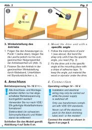
1. Bohren Sie an der Montagestelle ein Loch mit<br />
einem Durchmesser von 4 mm (Abb. 1).<br />
2. Führen Sie die Anschlusskabel zuerst durch<br />
das Montageloch und stecken Sie dann den<br />
<strong>Seilzug</strong> mit dem Befestigungsstift voran hinein.<br />
3. Befestigen Sie die Montageplatte des <strong>Seilzug</strong>es<br />
ggf. mit einem Tropfen Klebstoff am<br />
Montageort.<br />
4. Schrauben Sie das Schaltmodul nahe beim Antrieb<br />
unterflur an einen geeigneten Träger (z. B.<br />
Anlagengrundplatte oder Spanten). Die Kabel<br />
des <strong>Seilzug</strong>s müssen ohne mechanische Spannung<br />
bis zum Schaltmodul reichen.<br />
6. Anschluss und Betrieb<br />
Alle Anschluss- und Montagearbeiten dürfen<br />
nur bei abgeschalteter Betriebsspannung<br />
durchgeführt werden!<br />
Verwenden Sie nur nach VDE /EN-gefertigte<br />
Modellbahntransformatoren!<br />
Sichern Sie die Stromquellen unbedingt so<br />
ab, dass es bei einem Kurzschluss nicht<br />
zum Kabelbrand kommen kann.<br />
Die Betriebsspannung beträgt 16 V = / ~.<br />
Schließen Sie den <strong>Seilzug</strong> und das Schaltmodul<br />
gemäß den Abbildungen 3 oder 4 an.<br />
Gleichstrombetrieb: Schließen Sie das gelbe<br />
Kabel an den Minuspol des Trafos an.<br />
Analoge Ansteuerung<br />
Abbildung 3 zeigt, wie Sie den <strong>Seilzug</strong> mit Hilfe<br />
des <strong>Viessmann</strong> Tastenstellpultes 5547 anschließen<br />
können. Taster anderer Hersteller können Sie<br />
natürlich auch nutzen.<br />
Digitale Ansteuerung<br />
Der <strong>Viessmann</strong>-<strong>Seilzug</strong> kann auch von einem Digitalsystem<br />
angesteuert werden (Abb. 4). Beim<br />
Anschluss z. B. an den <strong>Viessmann</strong>-Magnetartikeldecoder<br />
5212 müssen Sie darauf achten, dass<br />
der rote und grüne Anschluss zur Steuerung gemeinsam<br />
beschaltet werden, damit jeder Tastendruck<br />
die Funktion des <strong>Seilzug</strong>es auslöst. Zum digitalen<br />
Schalten des <strong>Seilzug</strong>es benötigen Sie eine<br />
Ausgangsgruppe eines Magnetartikeldecoders.<br />
Der Magnetartikeldecoder 5212 (4-fach) ist kompatibel<br />
zu Märklin-Motorola und DCC. Damit lässt<br />
er sich mit den meisten am Markt vorhandenen<br />
Digitalzentralen wie z. B. <strong>Viessmann</strong> Commander,<br />
Digital plus (Lenz), Roco Digital, Fleischmann<br />
Twin Center, Digitrax, Uhlenbrock Intellibox, Tillig<br />
Digital, Märklin CS2 usw. steuern.<br />
5. Mounting<br />
1. Check that the electrical cable winch works<br />
properly as per the instructions above before<br />
you start installing it on the layout.<br />
2. Drill a hole of 4 mm diameter at the mounting<br />
place (Fig. 1).<br />
3. Insert the connection wires into the hole first.<br />
Then put the winch with the mounting foot<br />
into the hole.<br />
4. If needed, stick the mounting plate with a<br />
little bit of glue to the wall.<br />
5. Fix the switching module with screws near to<br />
the electrical cable winch on a suitable support<br />
(e. g. the ground plate of your model railway).<br />
The cables of the winch unit have to reach<br />
the switching module.<br />
6. Connections & Wiring<br />
The operation voltage is 16 V AC or DC.<br />
Installation and electrical wiring may only<br />
be carried out while the power supply is<br />
switched off.<br />
Only use transfor mers compliant with<br />
VDE / EN standards.<br />
The power sources must be protected to<br />
prevent the risk of burning wires.<br />
Now make the electrical connection as per<br />
figures 3 or 4.<br />
Direct current: Connect the yellow cable to the<br />
negative pole of the power supply.<br />
Analogue Wiring<br />
The conventional wiring is shown in figure 3. It<br />
shows how you can connect the electrical winch<br />
to a push-button panel (e. g. 5547).<br />
Digital Control<br />
The <strong>Viessmann</strong> electrical cable winch can also<br />
be operated with a digital system. Refer to figure<br />
4 (see below) for the correct wiring.<br />
Simply connect the wires to a digital solenoid<br />
drive decoder (e.g. <strong>Viessmann</strong> 5212 for Mot.<br />
and DCC).<br />
Remind, that the control cable (green) is connected<br />
to the red and green output of the digital<br />
solenoid drive decoder.<br />
The digital decoder 5212 (4 outputs) is compatible<br />
to Märklin-Motorola and DCC. Therefore<br />
it is compatible with many digital command<br />
stations: <strong>Viessmann</strong> Commander, Digital plus<br />
(Lenz), Roco Digital, Fleischmann Twin Center,<br />
4