Manual for creation of milling file - Architektur TU Berlin
Manual for creation of milling file - Architektur TU Berlin
Manual for creation of milling file - Architektur TU Berlin

You also want an ePaper? Increase the reach of your titles
YUMPU automatically turns print PDFs into web optimized ePapers that Google loves.
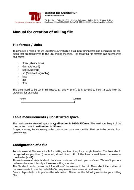
<strong>Manual</strong> <strong>for</strong> <strong>creation</strong> <strong>of</strong> <strong>milling</strong> <strong>file</strong><br />
File <strong>for</strong>mat / Units<br />
To generate a <strong>milling</strong> <strong>file</strong> we use RhinoCAM which is plug-in <strong>for</strong> Rhinoceros and generates the tool<br />
paths that are transferred to the CNC-<strong>milling</strong>-machine. The following <strong>file</strong> <strong>for</strong>mats can be imported<br />
and edited:<br />
• .3dm (Rhinoceros)<br />
• .dwg (Autocad)<br />
• .skp (Sketchup)<br />
• .stl (Stereolithography)<br />
• .iges<br />
• .dxf<br />
• .3ds<br />
The units need to be set in millimetres (1 unit = 1mm). It is advised to insert a scale into the<br />
drawings, <strong>for</strong> example:<br />
0mm<br />
100mm<br />
| |<br />
Table measurements / Constructed space<br />
The maximum constructed space in x,y-direction is 1000x750mm. The maximum height <strong>of</strong> the<br />
construction parts in z-direction is 50mm.<br />
In special cases, like engraving, taller construction parts are possible. That has to be decided from<br />
case to case.<br />
Configuration <strong>of</strong> a <strong>file</strong><br />
Two-dimensional <strong>file</strong>s are suitable <strong>for</strong> cutting contour lines, <strong>for</strong> example facades. The lines should<br />
be applied as poly-lines (connected, closed lines). All <strong>of</strong> the lines should have the same z-<br />
coordinates (z=0).<br />
Three-dimensional objects should be closed volumes without open surfaces. We can´t produce<br />
undercuts because it is only a three-axe <strong>milling</strong> machine.<br />
The <strong>file</strong> should only contain the in<strong>for</strong>mation <strong>of</strong> the volume to be cut. Think about the position <strong>of</strong><br />
the components to use the material effectively (saves time, material and costs).<br />
Created layers help us to process the in<strong>for</strong>mation. Please use the following names <strong>for</strong> your <strong>milling</strong><br />
<strong>file</strong>s:
• Außenkontur/outer contours (to cut the outer geometries [2D])<br />
• Innenkontur/ inner contours (to cut the inner geometries [2D])<br />
• Gravur/ engrave (to engrave [2D and 3D])<br />
• Tasche/ pocket (to mark a recess, <strong>for</strong> example relief façades [2D and 3D])<br />
• Geometry (<strong>for</strong> volumes [3D])<br />
Costs<br />
To compensate mechanical wear we have to charge a user fee:<br />
15 Cent/Min | 9 Euro/Std<br />
The given costs depend on the <strong>milling</strong> time which depend on the size and complexity <strong>of</strong> your<br />
model and the choice <strong>of</strong> material.<br />
Materials and material thickness<br />
the following materials can be used:<br />
• solid wood<br />
• medium density fibreboard (MDF)<br />
• chipboard<br />
• plywood<br />
• block-board<br />
• acrylic glass (only casted acrylic glass [GS], no extruded acrylic glass [XT])<br />
• polyurethane (known as PU or PUR)<br />
• styrodur<br />
The material thickness depend on the diameter <strong>of</strong> the miller. In general the thinner the miller the<br />
smaller the cutting depth.<br />
miller<br />
miller depth<br />
• 1,0mm 4mm<br />
• 1,5mm 8mm<br />
• 2,0mm 10mm<br />
• 3,0mm 15mm<br />
• 6,0mm 30mm