Testing Report - RhinoCo Technology
Testing Report - RhinoCo Technology
Testing Report - RhinoCo Technology

Create successful ePaper yourself
Turn your PDF publications into a flip-book with our unique Google optimized e-Paper software.
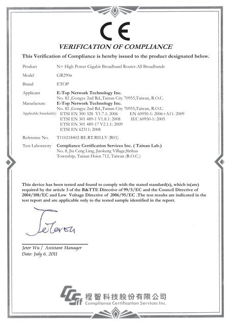
VERIFICATION OF COMPLIANCE<br />
This Verification of Compliance is hereby issued to the product designated below.<br />
Product<br />
Model<br />
Brand<br />
N+ High Power Gigabit Broadband Router-All Broadbands<br />
GR290n<br />
ETOP<br />
Applicant E-Top Network <strong>Technology</strong> Inc.<br />
No. 82 ,Gongye 2nd Rd.,Tainan City 70955,Taiwan, R.O.C.<br />
Manufacture E-Top Network <strong>Technology</strong> Inc.<br />
No. 82 ,Gongye 2nd Rd.,Tainan City 70955,Taiwan, R.O.C.<br />
Applicable Standard(s) ETSI EN 300 328 V1.7.1: 2006 EN 60950-1: 2006+A11: 2009<br />
ETSI EN 301 489-1 V1.8.1: 2008 IEC 60950-1: 2005<br />
ETSI EN 301 489-17 V2.1.1: 2009<br />
ETSI EN 62311: 2008<br />
Reference No.<br />
Test Laboratory<br />
T110218402-RE.RT.RH.LV (R01)<br />
Compliance Certification Services Inc. ( Tainan Lab.)<br />
No. 8, Jiu Ceng Ling, Jiaokeng Village,Sinhua<br />
Township, Tainan Hsien 712, Taiwan (R.O.C.)<br />
This device has been tested and found to comply with the stated standard(s), which is(are)<br />
required by the article 3 of the R&TTE Directive of 99/5/EC and the Council Directive of<br />
2004/108/EC and Low Voltage Directive of 2006/95/EC .The test results are indicated in the<br />
test report and are applicable only to the tested sample identified in the report.<br />
Jeter Wu / Assistant Manager<br />
Date: July 6, 2011
The following equipment:<br />
EC-Declaration of Conformity<br />
N+ High Power Gigabit Broadband Router-All Broadbands<br />
(Product Name)<br />
GR290n / ETOP<br />
(Model Designation / Trade Name)<br />
E-Top Network <strong>Technology</strong> Inc.<br />
(Manufacture Name)<br />
No. 82 ,Gongye 2nd Rd.,Tainan City 70955,Taiwan, R.O.C.<br />
(Manufacture Address)<br />
is hereby confirmed to comply with the requirements set out in the Council Directive on the<br />
Approximation of the Laws of the Member States relating to Radio Equipment and<br />
Telecommunications Terminal Equipment Directive (1999/5/EC) and Electromagnetic Compatibility<br />
Directive (2004/108/EC) and Low Voltage Directive (2006/95/EC). For the evaluation regarding the<br />
Radio Equipment and Telecommunications Terminal Equipment Directive (1999/5/EC) and<br />
Electromagnetic Compatibility Directive (2004/108/EC) and Low Voltage Directive (2006/95/EC),<br />
the following standards were applied:<br />
ETSI EN 300 328 V1.7.1: 2006 EN 60950-1: 2006+A11: 2009<br />
ETSI EN 301 489-1 V1.8.1: 2008 IEC 60950-1: 2005<br />
ETSI EN 301 489-17 V2.1.1: 2009<br />
ETSI EN 62311: 2008<br />
The following manufacturer / importer or authorized representative established within the EUT is<br />
responsible for this declaration:<br />
(Company Name)<br />
(Company Address)<br />
Person responsible for making this declaration:<br />
(Name, Surname)<br />
(Position / Title)<br />
(Place) (Date) (Legal Signature)
Multiple listing:<br />
Company & Address Brand Model Product Name<br />
GR290n<br />
N+ High Power Gigabit Broadband<br />
Router - All Broadbands<br />
E-Top Network <strong>Technology</strong> Inc.<br />
No. 82 ,Gongye 2nd Rd.,Tainan City<br />
70955,Taiwan,R.O.C.<br />
ETOP<br />
GR291d<br />
GS298d<br />
Wireless-N Concurrent Gigabit Router<br />
Wireless-N Concurrent Gigabit Server<br />
Router<br />
GR292n<br />
Wireless-N High Power Gigabit<br />
Broadband Router - All Broadbands<br />
RB-1733<br />
N+ Gigabit High Power Broadband<br />
Router - All Broadbands<br />
Sapido <strong>Technology</strong> Inc.<br />
No. 383., Sec. 2, Minsheng Rd., West<br />
Central District, Tainan 700, Taiwan,<br />
R.O.C.<br />
SAPIDO<br />
DR-1733<br />
DS-1763<br />
Simultaneous Dual-N Gigabit Router - All<br />
Broadbands<br />
Simultaneous Dual-N Gigabit NES<br />
Server - All Broadbands<br />
GR-1733<br />
N+ Gigabit Broadband Router - All<br />
Broadbands
Reference No: 90522403-RT<br />
<strong>Report</strong> No: T110218402-RT<br />
ETSI EN 300 328<br />
TEST REPORT<br />
For<br />
N+ High Power Gigabit Broadband Router-All Broadbands<br />
Model: GR290n<br />
Brand : ETOP<br />
Issued for<br />
E-Top Network <strong>Technology</strong> Inc.<br />
No. 82 ,Gongye 2nd Rd.,Tainan City 70955,Taiwan, R.O.C.<br />
Issued by<br />
Compliance Certification Services Inc.<br />
Tainan Lab.<br />
No. 8, Jiu Ceng Ling, Jiaokeng Village,Sinhua<br />
Township, Tainan Hsien 712, Taiwan (R.O.C.)<br />
TEL: 886-6-580-2201<br />
FAX: 886-6-580-2202<br />
Date of Issue: March 18, 2011<br />
Note: This report shall not be reproduced except in full, without the written approval of Compliance<br />
Certification Services Inc. Ltd. This document may be altered or revised by Compliance Certification<br />
Services Inc. personnel only, and shall be noted in the revision section of the document.<br />
Page 1 / 65
Reference No: 90522403-RT<br />
<strong>Report</strong> No: T110218402-RT<br />
Revision History<br />
Rev. Issue Date Revisions Effect Page Revised By<br />
00 March 18, 2011 Initial Issue ALL Daphne Liang<br />
01 July 07, 2011<br />
Add Model Name &<br />
Product Name<br />
Page 1, 2, 6<br />
Sunny Chang<br />
Page 2 / 65
Reference No: 90522403-RT<br />
<strong>Report</strong> No: T110218402-RT<br />
TABLE OF CONTENTS<br />
1. TEST REPORT CERTIFICATION.................................................................... 4<br />
2. EUT DESCRIPTION......................................................................................... 5<br />
3. DESCRIPTION OF TEST MODES................................................................... 7<br />
4. TEST METHODOLOGY................................................................................... 8<br />
5. FACILITIES AND ACCREDITATIONS ............................................................ 8<br />
5.1 FACILITIES ...............................................................................................................8<br />
5.2 EQUIPMENT .............................................................................................................8<br />
5.3 LABORATORY ACCREDITATIONS LISTINGS........................................................9<br />
5.4 TABLE OF ACCREDITATIONS AND LISTINGS ......................................................9<br />
6. CALIBRATION AND UNCERTAINTY................................................................. 10<br />
6.1 MEASURING INSTRUMENT CALIBRATION ...........................................................10<br />
6.2 MEASUREMENT UNCERTAINTY............................................................................10<br />
7. SETUP OF EQUIPMENT UNDER TEST............................................................. 11<br />
7.1 SETUP CONFIGURATION OF EUT .........................................................................11<br />
7.2 SUPPORT EQUIPMENT...........................................................................................11<br />
8. APPLICABLE LIMITS AND TEST RESULTS .................................................... 12<br />
8.1 EQUIVALENT ISOTROPIC RADIATED POWER .....................................................13<br />
8.2 MAXIMUM SPECTRAL POWER DENSITY..............................................................18<br />
8.3 FREQUENCY RANGE ..............................................................................................21<br />
8.4 TRANSMITTER SPURIOUS EMISSIONS ................................................................24<br />
8.5 RECEIVER SPURIOUS EMISSIONS .......................................................................44<br />
APPENDIX I PHOTOGRPHS OF TEST SETUP..................................................... 64<br />
APPENDIX II - PHOTOGRAPHS OF EUT…………………………………………....A1<br />
Page 3 / 65
Reference No: 90522403-RT<br />
<strong>Report</strong> No: T110218402-RT<br />
1. TEST REPORT CERTIFICATION<br />
Applicant<br />
Address<br />
Manufacture<br />
Address<br />
E-Top Network <strong>Technology</strong> Inc.<br />
No. 82 ,Gongye 2nd Rd.,Tainan City<br />
70955,Taiwan, R.O.C.<br />
E-Top Network <strong>Technology</strong> Inc.<br />
No. 82 ,Gongye 2nd Rd.,Tainan City<br />
70955,Taiwan, R.O.C.<br />
Equipment Under TestN+ High Power Gigabit Broadband<br />
Router-All Broadbands<br />
Model Number<br />
Brand Name<br />
GR290n<br />
ETOP<br />
Date of Test March 08, 2011 ~ March 16, 2011<br />
APPLICABLE STANDARD<br />
STANDARD<br />
TEST RESULT<br />
ETSI EN 300 328 V1.7.1 (2006)<br />
No non-compliance noted<br />
Approved by:<br />
Reviewed by:<br />
Jeter Wu<br />
Assistant Manager<br />
Eric Huang<br />
Assistant Section Engineer<br />
Page 4 / 65
Reference No: 90522403-RT<br />
<strong>Report</strong> No: T110218402-RT<br />
2. EUT DESCRIPTION<br />
Product Name<br />
Model Number<br />
Brand<br />
N+ High Power Gigabit Broadband Router-All Broadbands<br />
GR290n<br />
ETOP<br />
Received Date February 18, 2011<br />
IEEE 802.11b/g ,802.11n HT20:2412MHz2472MHz<br />
Frequency Range<br />
IEEE 802.11n HT40:2422MHz2462MHz<br />
IEEE 802.11b: 18.38 dBm<br />
IEEE 802.11g: 17.83 dBm<br />
Transmit Power<br />
IEEE 802.11n HT20: 18.55 dBm<br />
IEEE 802.11n HT40: 18.28 dBm<br />
Channel Spacing IEEE 802.11b/g, 802.11n HT20/HT40: 5MHz<br />
IEEE 802.11b/g, 802.11n HT20:13 Channels<br />
Channel Number<br />
IEEE 802.11n HT40 :9 Channels<br />
IEEE 802.11b:1,2,5.5,11Mbps<br />
IEEE 802.11g:6,9,12,18,24,36,48,54Mbps<br />
IEEE 802.11n HT20: 6.5,13,19.5,26,39,52,58.5,65,78,104,<br />
Transmit Data Rate<br />
117,130Mbps<br />
IEEE 802.11n HT40: 13.5,27,40.5,54,81,108,121.5,135,162,<br />
216,243,270Mbps<br />
IEEE 802.11bDSSS (CCK, DQPSK, DBPSK)<br />
IEEE 802.11gOFDM (64QAM, 16QAM, QPSK, BPSK)<br />
Type of Modulation<br />
IEEE 802.11n HT20/40OFDM (64QAM, 16QAM, QPSK,<br />
BPSK)<br />
Frequency Selection by software / firmware<br />
Two Antenna (2Tx 2RX)<br />
Dipole Antenna (2T2R)<br />
Manufacture: XINXIE TECHNOLOGYSHENZHENCO.LTD.<br />
Antenna Type<br />
Model: S22-XY30925<br />
Connector: i-pex<br />
Gain: 5 dBi<br />
Powered from adapter<br />
Manufacturer: Keen Ocean Industrial Ltd.<br />
Power Source<br />
Model: S02-012-0120-01000<br />
Input:100-240Vac, 50/60Hz 0.40A<br />
Output:12Vdc,1000mA<br />
NOTE: 1. Client consigns one model sample to test (Model Number: GR290n).<br />
Therefore, the testing Lab. just guarantees the unit, which has been tested.<br />
2. For more details, please refer to the User’s manual of the EUT.<br />
3. To add a series model is for business necessary. The different of the each model is<br />
shown as bellows:<br />
Page 5 / 65
<strong>Report</strong> No: T110218402-RT<br />
Multiple listing:<br />
I/O PORT<br />
I/O PORT TYPES Q’TY TESTED WITH<br />
N/A N/A N/A<br />
Page 6 / 65
<strong>Report</strong> No: T110218402-RT<br />
Reference No: 90522403-RT Date of Issue: March 18, 2011<br />
3. DESCRIPTION OF TEST MODES<br />
The EUT is a 11n router. It has two transmitter chains and two receiver<br />
chains (2x2 configurations). The 2x2 configuration is implemented with two<br />
outside chains (Chain 0 and Chain 1).<br />
The RF chipset is manufactured by Realtek Semiconductor Corp.<br />
The antenna peak gain 5dBi (highest gain) were chosen for full testing.<br />
IEEE 802.11 b ,802.11g ,802.11n HT20 mode (DTS Band)<br />
The EUT had been tested under operating condition.<br />
There are three channels have been tested as following:<br />
Channel<br />
Frequency (MHz)<br />
Low 2412<br />
Middle 2442<br />
High 2472<br />
IEEE 802.11b mode: 11Mbps data rate (worst case) were chosen for full testing.<br />
IEEE 802.11g mode: 6Mbps data rate (worst case) were chosen for full testing.<br />
IEEE 802.11n HT20 mode: 13Mbps data rate (worst case) were chosen for full<br />
testing.<br />
IEEE 802.11n HT40 mode (DTS Band)<br />
The EUT had been tested under operating condition.<br />
There are three channels have been tested as following:<br />
Channel<br />
Frequency (MHz)<br />
Low 2422<br />
Middle 2442<br />
High 2462<br />
IEEE 802.11n HT40 mode: 27Mbps data rate (worst case) were chosen for full<br />
testing.<br />
The worst-case data rates are determined according to the description above, based<br />
on the investigations by measuring the PSD, peak power and average power across<br />
all the data rates, bandwidths, modulations and spatial stream modes.<br />
Page 7
<strong>Report</strong> No: T110218402-RT<br />
Reference No: 90522403-RT Date of Issue: March 18, 2011<br />
4. TEST METHODOLOGY<br />
The tests documented in this report were performed in accordance with ETSI EN<br />
300 328 V1.7.1 : 2006 – Electromagnetic compatibility and Radio spectrum Matters<br />
(ERM) ; wideband transmission systems; data transmission equipment operating in<br />
the 2.4GHz ISM band and using spread spectrum modulation techniques:<br />
Harmonized EN covering essential requirements under article 3.2 of the R&TTE<br />
Directive.<br />
5. FACILITIES AND ACCREDITATIONS<br />
5.1 FACILITIES<br />
All measurement facilities used to collect the measurement data are located at<br />
No. 8, Jiu Ceng Ling, Jiaokeng Village,Sinhua Township, Tainan Hsien 712,<br />
Taiwan (R.O.C.)<br />
The sites are constructed in conformance with the requirements of ANSI C63.7,<br />
ANSI C63.4 and CISPR Publication 22.<br />
5.2 EQUIPMENT<br />
Radiated emissions are measured with one or more of the following types of<br />
linearly polarized antennas: tuned dipole, biconical, log periodic, bi-log, and/or<br />
ridged waveguide, horn. Spectrum analyzers with preselectors and quasi-peak<br />
detectors are used to perform radiated measurements.<br />
Conducted emissions are measured with Line Impedance Stabilization Networks<br />
and EMI Test Receivers.<br />
Calibrated wideband preamplifiers, coaxial cables, and coaxial attenuators are also<br />
used for making measurements.<br />
All receiving equipment conforms to CISPR Publication 16-1, “Radio Interference<br />
Measuring Apparatus and Measurement Methods.”<br />
Page 8
<strong>Report</strong> No: T110218402-RT<br />
Reference No: 90522403-RT Date of Issue: March 18, 2011<br />
5.3 LABORATORY ACCREDITATIONS LISTINGS<br />
The test facilities used to perform radiated and conducted emissions tests are<br />
accredited by Taiwan Accreditation Foundation for the specific scope of<br />
accreditation under Lab Code: 1109 to perform Electromagnetic Interference tests<br />
according to FCC PART 15 AND CISPR 22 requirements. No part of this report<br />
may be used to claim or imply product endorsement by TAF or any agency of the<br />
Government. In addition, the test facilities are listed with Federal Communications<br />
Commission (registration no: TW-1037 ).<br />
5.4 TABLE OF ACCREDITATIONS AND LISTINGS<br />
Our laboratories are accredited and approved by the following accreditation body<br />
according to ISO/IEC 17025.<br />
Taiwan<br />
TAF<br />
The measuring facility of laboratories has been authorized or registered by the following<br />
approval agencies.<br />
Canada<br />
Germany<br />
Taiwan<br />
USA<br />
Industry Canada<br />
TUV Rheinland<br />
BSMI<br />
FCC<br />
Copies of granted accreditation certificates are available for downloading from our web<br />
site, http:///www.ccsrf.com<br />
Page 9
<strong>Report</strong> No: T110218402-RT<br />
Reference No: 90522403-RT Date of Issue: March 18, 2011<br />
6. CALIBRATION AND UNCERTAINTY<br />
6.1 MEASURING INSTRUMENT CALIBRATION<br />
The measuring equipment utilized to perform the tests documented in this report<br />
has been calibrated in accordance with the manufacturer’s recommendations, and<br />
is traceable to recognized national standards.<br />
6.2 MEASUREMENT UNCERTAINTY<br />
Where relevant, the following measurement uncertainty levels have been estimated<br />
for tests performed on the apparatus:<br />
Parameter<br />
Uncertainty<br />
Radio Frequency ±0.523 x 10⁻⁵<br />
Total RF power, conducted<br />
±1.3dB<br />
RF power density, conducted<br />
±2.5dB<br />
Spurious emissions, conducted<br />
±2.6dB<br />
All emissions, radiated<br />
±4dB<br />
Temperature ±1℃<br />
Humidity ±3.2%<br />
DC and low frequency voltages ±1.8%<br />
Uncertainty figures are valid to a confidence level of 95%, k=2<br />
Page 10
<strong>Report</strong> No: T110218402-RT<br />
Reference No: 90522403-RT Date of Issue: March 18, 2011<br />
7. SETUP OF EQUIPMENT UNDER TEST<br />
7.1 SETUP CONFIGURATION OF EUT<br />
(A)<br />
(B)<br />
E.U.T.<br />
Adapter<br />
NB<br />
(1)<br />
7.2 SUPPORT EQUIPMENT<br />
No. Product Manufacturer Model No. Certify No. Signal cable<br />
1 3G Modem NOVATEL<br />
Qualcomm<br />
3G CDMA<br />
PKRNVWMC<br />
727<br />
2 Note Book IBM R51 R33026 Power cable, unshd, 1.6m<br />
3 Note Book IBM T43 DOC Power cable, unshd, 1.6m<br />
N/A<br />
No. Signal cable description<br />
A DC Unshielded, 1.8m, 1pcs.<br />
B LAN Unshielded, 10m, 1pcs.<br />
Remark:<br />
1. All the above equipment/cables were placed in worse case positions to maximize emission<br />
signals during emission test.<br />
2. Grounding was established in accordance with the manufacturer’s requirements and<br />
conditions for the intended use.<br />
Page 11
<strong>Report</strong> No: T110218402-RT<br />
Reference No: 90522403-RT Date of Issue: March 18, 2011<br />
7.3 EUT OPERATING CONDITION<br />
RF Setup<br />
1. Set up all computers like the setup diagram.<br />
2. The “Realtek MP Test Program” software was used for testing<br />
TX Mode:<br />
Tx Mode:CCK 、OFDM、 HT MixMode (Bandwidth: 20、40)<br />
Tx Data Rate: 11Mbps long (IEEE 802.11b mode ,chain 0 TX)<br />
6Mbps (IEEE 802.11g mode ,chain 0 TX)<br />
13Mbps (IEEE 802.11n HT20 mode ,chain 0, chain 1 TX)<br />
27Mbps (IEEE 802.11n HT40 mode, chain 0, chain 1 TX)<br />
Power control mode<br />
Target Power: IEEE 802.11b Channel Low (2412MHz) = 32 (Chain 0)<br />
IEEE 802.11b Channel Middle (2442MHz) = 32 (Chain 0)<br />
IEEE 802.11b Channel High (2472MHz) = 32 (Chain 0)<br />
Target Power: IEEE 802.11g Channel Low (2412MHz) = 40 (Chain 0)<br />
IEEE 802.11g Channel Middle (2442MHz) = 40 (Chain 0)<br />
IEEE 802.11g Channel High (2472MHz) = 40 (Chain 0)<br />
Target Power: IEEE 802.11n HT20 Channel Low (2412MHz) = 33 (Chain 0)<br />
IEEE 802.11 n HT20 Channel Middle (2442MHz) = 33 (Chain 0)<br />
IEEE 802.11 n HT20 Channel High (2472MHz) = 33 (Chain 0)<br />
IEEE 802.11n HT20 Channel Low (2412MHz) = 33 (Chain 1)<br />
IEEE 802.11 n HT20 Channel Middle (2442MHz) = 33 (Chain 1)<br />
IEEE 802.11 n HT20 Channel High (2472MHz) = 33 (Chain 1)<br />
Target Power: IEEE 802.11n HT40 Channel Low (2422MHz) = 33 (Chain 0)<br />
IEEE 802.11 n HT40 Channel Middle (2442MHz) = 33 (Chain 0)<br />
IEEE 802.11 n HT40 Channel High (2462MHz) = 33 (Chain 0)<br />
IEEE 802.11n HT40 Channel Low (2422MHz) = 33 (Chain 1)<br />
IEEE 802.11 n HT40 Channel Middle (2442MHz) = 33 (Chain 1)<br />
IEEE 802.11 n HT40 Channel High (2462MHz) = 33 (Chain 1)<br />
(2) RX Mode:<br />
Start RX<br />
3. All of the function are under run.<br />
4. Start test.<br />
Normal Link Setup<br />
1. Set up all computers like the setup diagram.<br />
2. All of the function are under run.<br />
3. Notebook PC (2) ping 192.168.0.10 –t to Notebook PC (1).<br />
4. Notebook PC (1) ping 192.168.0.20 –t to Notebook PC (2).<br />
5. Notebook PC (1) ping 192.168.0.50 –t to Wireless Access Point (3).<br />
Start test.<br />
Page 12
<strong>Report</strong> No: T110218402-RT<br />
Reference No: 90522403-RT Date of Issue: March 18, 2011<br />
8. APPLICABLE LIMITS AND TEST RESULTS<br />
8.1 EQUIVALENT ISOTROPIC RADIATED POWER<br />
LIMIT<br />
EN 300 328 Clause 4.3.1<br />
The equivalent isotropic radiated power shall be equal to or less than -10 dBW (100<br />
mW) e.i.r.p. This limit shall apply for any combination of power level and intended<br />
antenna assembly.<br />
TEST EQUIPMENTS<br />
Name of<br />
Equipment<br />
Manufacturer Model Serial Number Calibration Due<br />
Temp./Humidity<br />
Chamber<br />
K.SON THS-M1 242 AUG. 11, 2011<br />
Power Meter Anritsu ML2487A 6K00003888 MAY 11, 2011<br />
TEST SETUP<br />
Temperature Chamber<br />
Power Meter<br />
EUT<br />
Variable power supply<br />
TEST PROCEDURE<br />
1. .Please refer to ETSI EN 300 328 (V1.6.1) clause 5.3 for the test conditions.<br />
2. Please refer to ETSI EN 300 328 (V1.7.1) clause 5.7.2.2 for the measurement<br />
method.<br />
TEST RESULTS<br />
No non-compliance noted<br />
Page 13
<strong>Report</strong> No: T110218402-RT<br />
Reference No: 90522403-RT Date of Issue: March 18, 2011<br />
N+ High Power Gigabit Broadband<br />
Product Name<br />
Router-All Broadbands<br />
Test Date 2011/3/10<br />
Model GR290n Test By John Chen<br />
Test Mode IEEE 802.11b TEMP& Humidity 23.2℃,55%<br />
Duty Cycle measurement X: (Ton/Ton + Toff) = 1.00<br />
10 * log (1/x) = 0.00 dB<br />
Antenna Assembly Gain: 5 dBi<br />
Cable Loss= 0.1 dB<br />
TEST CONDITIONS<br />
TRANSMITTER POWER (dBm)<br />
T nom ( 25 ° C ) T min ( 0 ° C ) T max ( 55 ° C )<br />
CHANNEL<br />
Low<br />
Middle<br />
High<br />
Voltage<br />
Power<br />
Limit<br />
Measurement<br />
Uncertainty<br />
230VAC 207VAC 253VAC 207VAC 253VAC<br />
Chain0 Total Chain0 Total Chain0 Total Chain0 Total Chain0 Total<br />
Measured<br />
11.33 13.03 13.15 9.15 9.12<br />
Power<br />
16.43<br />
18.13<br />
18.25<br />
14.25<br />
14.22<br />
EIRP 16.43<br />
18.13<br />
18.25<br />
14.25<br />
14.22<br />
Measured<br />
11.41 13.28 13.21 9.12 9.15<br />
Power<br />
16.51<br />
18.38<br />
18.31<br />
14.22<br />
EIRP 16.51<br />
18.38<br />
18.31<br />
14.22<br />
14.25<br />
Measured<br />
11.32 13.17 13.15 8.90 9.11<br />
Power<br />
16.42<br />
18.27<br />
18.25<br />
14.00<br />
EIRP 16.42<br />
18.27<br />
18.25<br />
14.00<br />
14.21<br />
Average Limit = 20 dBm<br />
+ 0.28dB / - 0.30dB<br />
14.25<br />
14.21<br />
Page 14
<strong>Report</strong> No: T110218402-RT<br />
Reference No: 90522403-RT Date of Issue: March 18, 2011<br />
N+ High Power Gigabit Broadband<br />
Product Name<br />
Router-All Broadbands<br />
Test Date 2011/3/10<br />
Model GR290n Test By John Chen<br />
Test Mode IEEE 802.11g TEMP& Humidity 23.2℃,55%<br />
Duty Cycle measurement X: (Ton/Ton + Toff) = 1.00<br />
10 * log (1/x) = 0.00 dB<br />
Antenna Assembly Gain: 5 dBi<br />
Cable Loss= 0.1 dB<br />
TEST CONDITIONS<br />
TRANSMITTER POWER (dBm)<br />
T nom ( 25 ° C ) T min ( 0 ° C ) T max ( 55 ° C )<br />
CHANNEL<br />
Low<br />
Middle<br />
High<br />
Voltage<br />
Power<br />
Limit<br />
Measurement<br />
Uncertainty<br />
230VAC 207VAC 253VAC 207VAC 253VAC<br />
Chain0 Total Chain0 Total Chain0 Total Chain0 Total Chain0 Total<br />
Measured<br />
10.87 12.52 12.35 8.27 8.26<br />
Power<br />
15.97<br />
17.62<br />
17.45<br />
13.37<br />
13.36<br />
EIRP 15.97<br />
17.62<br />
17.45<br />
13.37<br />
13.36<br />
Measured<br />
10.85 12.62 12.38 8.38 8.26<br />
Power<br />
15.95<br />
17.72<br />
17.48<br />
13.48<br />
EIRP 15.95<br />
17.72<br />
17.48<br />
13.48<br />
13.36<br />
Measured<br />
10.86 12.73 12.28 8.56 8.24<br />
Power<br />
15.96<br />
17.83<br />
17.38<br />
13.66<br />
EIRP 15.96<br />
17.83<br />
17.38<br />
13.66<br />
13.34<br />
Average Limit = 20 dBm<br />
+ 0.28dB / - 0.30dB<br />
13.36<br />
13.34<br />
Page 15
<strong>Report</strong> No: T110218402-RT<br />
Reference No: 90522403-RT Date of Issue: March 18, 2011<br />
N+ High Power Gigabit Broadband<br />
Product Name<br />
Router-All Broadbands<br />
Test Date 2011/03/10<br />
Model GR290n Test By John Chen<br />
Test Mode IEEE 802.11HT20 TEMP& Humidity 23.2℃,55%<br />
Duty Cycle measurement X: (Ton/Ton + Toff) = 1.00<br />
10 * log (1/x) = 0.00 dB<br />
Antenna Assembly Gain: 5 dBi<br />
Cable Loss= 0.1 dB<br />
TEST<br />
CONDITIONS<br />
TRANSMITTER POWER (dBm)<br />
T nom ( 25 ° C ) T min ( 0 ° C ) T max ( 55 ° C )<br />
CHANN<br />
EL<br />
Low<br />
Voltage<br />
Power<br />
230VAC 207VAC 253VAC 207VAC 253VAC<br />
Chain0 Chain1 Total Chain0 Chain1 Total Chain0 Chain1 Total Chain0 Chain1 Total Chain0 Chain1 Total<br />
Measured<br />
6.86 9.08 8.40 11.60 8.37 11.56 4.83 6.71 4.85 6.75<br />
Power<br />
16.22<br />
18.40<br />
18.36<br />
13.98<br />
14.01<br />
EIRP 11.96 14.18<br />
13.50 16.70<br />
13.47 16.66<br />
9.93 11.81<br />
9.95 11.85<br />
Measured<br />
6.87 9.13 8.52 11.76 8.35 11.57 4.81 6.78 4.84 6.77<br />
Power<br />
Middle<br />
16.26<br />
18.55<br />
18.36<br />
14.02<br />
14.02<br />
EIRP 11.97 14.23<br />
13.62 16.86<br />
13.45 16.67<br />
9.91 11.88<br />
9.94 11.87<br />
High<br />
Measured<br />
6.67 9.12 8.51 11.65 8.42 11.48 4.67 6.59 4.80 6.64<br />
Power<br />
16.18<br />
18.47<br />
18.32<br />
13.85<br />
EIRP 11.77 14.22<br />
13.61 16.75<br />
13.52 16.58<br />
9.77 11.69<br />
9.90 11.74<br />
Limit<br />
Measurement<br />
Uncertainty<br />
Average Limit = 20 dBm<br />
+ 0.28dB / - 0.30dB<br />
13.93<br />
Page 16
<strong>Report</strong> No: T110218402-RT<br />
Reference No: 90522403-RT Date of Issue: March 18, 2011<br />
N+ High Power Gigabit Broadband<br />
Product Name<br />
Router-All Broadbands<br />
Test Date 2011/03/10<br />
Model GR290n Test By John Chen<br />
Test Mode IEEE 802.11HT40 TEMP& Humidity 23.2℃,55%<br />
Duty Cycle measurement X: (Ton/Ton + Toff) = 1.00<br />
10 * log (1/x) = 0.00 dB<br />
Antenna Assembly Gain: 5 dBi<br />
Cable Loss= 0.1 dB<br />
TEST<br />
CONDITIONS<br />
TRANSMITTER POWER (dBm)<br />
T nom ( 25 ° C ) T min ( 0 ° C ) T max ( 55 ° C )<br />
CHANN<br />
EL<br />
Low<br />
Voltage<br />
Power<br />
230VAC 207VAC 253VAC 207VAC 253VAC<br />
Chain0 Chain1 Total Chain0 Chain1 Total Chain0 Chain1 Total Chain0 Chain1 Total Chain0 Chain1 Total<br />
Measured<br />
6.58 8.82 8.09 11.45 8.26 11.45 4.56 6.37 4.62 6.34<br />
Power<br />
15.95<br />
18.20<br />
18.25<br />
13.67<br />
13.67<br />
EIRP 11.68 13.92<br />
13.19 16.55 13.36 16.55<br />
9.66 11.47<br />
9.72 11.44<br />
Measured<br />
6.57 8.87 8.41 11.42 8.34 11.46 4.47 6.31 4.61 6.28<br />
Power<br />
Middle<br />
15.98<br />
18.28<br />
18.28<br />
13.60<br />
EIRP 11.67 13.97<br />
13.51 16.52 13.44 16.56<br />
9.57 11.41<br />
9.71 11.38<br />
High<br />
Measured<br />
6.46 8.81 8.29 11.46 8.18 11.44 4.39 6.32 4.58 6.31<br />
Power<br />
15.90<br />
18.27<br />
18.22<br />
13.57<br />
EIRP 11.56 13.91<br />
13.39 16.56 13.28 16.54<br />
9.49 11.42<br />
9.68 11.41<br />
Limit<br />
Measurement<br />
Uncertainty<br />
Average Limit = 20 dBm<br />
+ 0.28dB / - 0.30dB<br />
13.64<br />
13.64<br />
Page 17
<strong>Report</strong> No: T110218402-RT<br />
Reference No: 90522403-RT Date of Issue: March 18, 2011<br />
8.2 MAXIMUM SPECTRAL POWER DENSITY<br />
LIMIT<br />
EN 300 328 Clause 4.3.2.2<br />
For wide band modulations other then FHSS (e.g. DSSS, OFDM, etc.), the maximum<br />
spectrum power density is limited to 10 mW per MHz e.i.r.p.<br />
TEST EQUIPMENTS<br />
Name of<br />
Equipment<br />
Manufacturer Model Serial Number Calibration Due<br />
Temp./Humidity<br />
Chamber<br />
K.SON THS-M1 242 AUG. 11, 2011<br />
Power Meter Anritsu ML2487A 6K00003888 MAY 11, 2011<br />
TEST SETUP<br />
Spectrum<br />
Analzyer<br />
IF<br />
RF<br />
Anritsu<br />
Power meter<br />
EUT<br />
TEST PROCEDURE<br />
1. Please refer to ETSI EN 300 328 (V1.7.1) clause 5.3 for the test conditions.<br />
2. Please refer to ETSI EN300 328 (V1.7.1) clause 5.7.3 for the measurement<br />
method.<br />
TEST RESULTS<br />
No non-compliance noted<br />
Page 18
<strong>Report</strong> No: T110218402-RT<br />
Reference No: 90522403-RT Date of Issue: March 18, 2011<br />
N+ High Power Gigabit Broadband<br />
Product Name<br />
Router-All Broadbands<br />
Test Date 2011/3/10<br />
Model GR290n Test By John Chen<br />
Mode IEEE 802.11b TEMP & Humidity 23.2℃,55%<br />
TEST<br />
CONDITIONS<br />
Low<br />
(dBm/MHz)<br />
Measured<br />
Mid<br />
Power<br />
(dBm/MHz)<br />
Density<br />
High<br />
(dBm/MHz)<br />
Limit<br />
Measurement<br />
Uncertainty<br />
Measured Power Density<br />
Reading<br />
(A) Chain 0<br />
Antenna<br />
Gain<br />
(B)<br />
10*log<br />
(1/x) (C)<br />
Cable<br />
loss<br />
(D)<br />
Measured Power<br />
Density<br />
Result (A+B+C+D)<br />
-1.62 4.88<br />
-1.57 5.00 0.00 1.50<br />
4.93<br />
-1.66<br />
10 dBm / MHz<br />
+1.5dB / -1.4dB<br />
N+ High Power Gigabit Broadband<br />
Product Name<br />
Router-All Broadbands<br />
Test Date 2011/3/10<br />
Model GR290n Test By John Chen<br />
Mode IEEE 802.11g TEMP & Humidity 23.2℃,55%<br />
4.84<br />
TEST<br />
CONDITIONS<br />
Low<br />
(dBm/MHz)<br />
Measured<br />
Mid<br />
Power<br />
(dBm/MHz)<br />
Density<br />
High<br />
(dBm/MHz)<br />
Limit<br />
Measurement<br />
Uncertainty<br />
Measured Power Density<br />
Reading Chain 0<br />
(A)<br />
Antenna<br />
Gain<br />
(B)<br />
10*log<br />
(1/x) (C)<br />
Cable<br />
loss<br />
(D)<br />
Measured Power<br />
Density<br />
Result (A+B+C+D)<br />
-1.45 5.05<br />
-1.53 5.00 0.00 1.50<br />
4.97<br />
-1.58<br />
10 dBm / MHz<br />
+1.5dB / -1.4dB<br />
4.92<br />
Page 19
<strong>Report</strong> No: T110218402-RT<br />
Reference No: 90522403-RT Date of Issue: March 18, 2011<br />
N+ High Power Gigabit Broadband<br />
Product Name<br />
Router-All Broadbands<br />
Test Date 2011/3/10<br />
Model GR290n Test By John Chen<br />
Mode IEEE 802.11n HT20 TEMP & Humidity 23.2℃,55%<br />
TEST<br />
CONDITIONS<br />
Measured Measured<br />
Power Power<br />
Density Density<br />
Reading(A0) Reading(A<br />
ChainA 1) ChainC<br />
Antenna<br />
Gain (B)<br />
10*log<br />
(1/x) (C)<br />
Cable<br />
loss (D)<br />
Measured<br />
Power<br />
Density<br />
Result<br />
(A0+B+C+D)<br />
Chain0<br />
Measured<br />
Measured Power<br />
Power Density<br />
Density Result<br />
Result<br />
Total<br />
(A1+B+C+D)<br />
(ch0+ch1+ch2)<br />
Chain1<br />
Low<br />
(dBm/MHz)<br />
Measured<br />
Mid<br />
Power<br />
(dBm/MHz)<br />
Density<br />
High<br />
(dBm/MHz)<br />
Limit<br />
Measurement<br />
Uncertainty<br />
-3.74 -2.95 2.76 3.55 6.18<br />
-3.33 -2.74 5.00 0.00 1.50 3.17 3.76 6.49<br />
-3.50 -2.87<br />
3.00 3.63 6.34<br />
10 dBm / MHz<br />
+1.5dB / -1.4dB<br />
N+ High Power Gigabit Broadband<br />
Product Name<br />
Router-All Broadbands<br />
Test Date 2011/3/10<br />
Model GR290n Test By John Chen<br />
Mode IEEE 802.11n HT40 TEMP & Humidity 23.2℃,55%<br />
TEST<br />
CONDITIONS<br />
Measured Measured<br />
Power Power<br />
Density Density<br />
Reading(A0) Reading(A<br />
ChainA 1) ChainC<br />
Antenna<br />
Gain (B)<br />
10*log<br />
(1/x) (C)<br />
Cable<br />
loss (D)<br />
Measured<br />
Power<br />
Density<br />
Result<br />
(A0+B+C+D)<br />
Chain0<br />
Measured<br />
Measured Power<br />
Power Density<br />
Density Result<br />
Result<br />
Total<br />
(A1+B+C+D)<br />
(ch0+ch1+ch2)<br />
Chain1<br />
Low<br />
(dBm/MHz)<br />
Measured<br />
Mid<br />
Power<br />
(dBm/MHz)<br />
Density<br />
High<br />
(dBm/MHz)<br />
Limit<br />
Measurement<br />
Uncertainty<br />
-3.89 -3.05 2.61 3.45 6.06<br />
-4.12 -2.95 5.00 0.00 1.50 2.38 3.55 6.01<br />
-4.08 -3.14<br />
2.42 3.36 5.93<br />
10 dBm / MHz<br />
+1.5dB / -1.4dB<br />
Page 20
<strong>Report</strong> No: T110218402-RT<br />
Reference No: 90522403-RT Date of Issue: March 18, 2011<br />
8.3 FREQUENCY RANGE<br />
LIMIT<br />
EN 300 328 Clause 4.3.3.2<br />
For all equipment the frequency shall lie within the band 2.4GHz to 2.4835GHz<br />
(fL>2.4GHz and fH
<strong>Report</strong> No: T110218402-RT<br />
Reference No: 90522403-RT Date of Issue: March 18, 2011<br />
TEST RESULTS<br />
No non-compliance noted<br />
N+ High Power Gigabit Broadband<br />
Product Name<br />
Router-All Broadbands<br />
Test Date 2011/03/10<br />
Model GR290n Test By John Chen<br />
Mode IEEE 802.11b TEMP & Humidity 23.2℃,55%<br />
Frequency Range<br />
TEST CONDITIONS Low Frequency<br />
High Frequency<br />
MHz<br />
MHz<br />
T nom (25 ° C) 230V 2403.98 2479.72<br />
T min (0 ° C)<br />
207V 2403.53 2480.12<br />
253V 2403.55 2480.62<br />
T max (55 ° C)<br />
Measured frequencies<br />
(lowest and highest)<br />
207V 2404.43 2479.27<br />
253V 2404.25 2479.82<br />
2403.53 2480.62<br />
Limit FL > 2400MHz FH < 2483.5MHz<br />
Measurement uncertainty<br />
+/- 120kHz<br />
N+ High Power Gigabit Broadband<br />
Product Name<br />
Router-All Broadbands<br />
Test Date 2011/03/10<br />
Model GR290n Test By John Chen<br />
Mode IEEE 802.11g TEMP & Humidity 23.2℃,55%<br />
Frequency Range<br />
TEST CONDITIONS Low Frequency<br />
High Frequency<br />
MHz<br />
MHz<br />
T nom (25 ° C) 230V 2403.63 2480.37<br />
T min (0 ° C)<br />
207V 2403.43 2480.52<br />
253V 2403.60 2403.38<br />
T max (55 ° C)<br />
Measured frequencies<br />
(lowest and highest)<br />
207V 2403.63 2480.32<br />
253V 2403.63 2480.38<br />
2403.43 2480.52<br />
Limit FL > 2400MHz FH < 2483.5MHz<br />
Measurement uncertainty<br />
+/- 120kHz<br />
Page 22
<strong>Report</strong> No: T110218402-RT<br />
Reference No: 90522403-RT Date of Issue: March 18, 2011<br />
N+ High Power Gigabit Broadband<br />
Product Name<br />
Router-All Broadbands<br />
Test Date 2011/03/10<br />
Model GR290n Test By John Chen<br />
Mode IEEE 802.11n HT20 TEMP & Humidity 23.2℃,55%<br />
Frequency Range<br />
TEST CONDITIONS Low Frequency(MHz) High Frequency(MHz)<br />
Chain 0 Chain 1 Chain 0 Chain 1<br />
T nom (25 ° C) 230V 2403.03 2403.03 2480.92 2480.97<br />
T min (0 ° C)<br />
207V 2403.03 2402.98 2480.97 2480.97<br />
253V 2403.05 2403.05 2480.86 2480.88<br />
T max (55 ° C)<br />
Measured frequencies<br />
(lowest and highest)<br />
207V 2403.08 2403.03 2480.92 2480.92<br />
253V 2403.10 2403.08 2480.91 2480.91<br />
2403.03 2402.98 2480.97 2480.97<br />
Limit FL > 2400MHz FH < 2483.5MHz<br />
Measurement uncertainty<br />
+/- 120kHz<br />
N+ High Power Gigabit Broadband<br />
Product Name<br />
Router-All Broadbands<br />
Test Date 2011/03/10<br />
Model GR290n Test By John Chen<br />
Mode IEEE 802.11n HT40 TEMP & Humidity 23.2℃,55%<br />
Frequency Range<br />
TEST CONDITIONS Low Frequency(MHz) High Frequency(MHz)<br />
Chain 0 Chain 0<br />
T nom (25 ° C) 230V 2403.73 2403.68 2480.17 2480.27<br />
T min (0 ° C)<br />
207V 2403.68 2403.68 2480.27 2480.32<br />
253V 2403.68 2403.62 2480.25 2480.25<br />
T max (55 ° C)<br />
Measured frequencies<br />
(lowest and highest)<br />
207V 2403.73 2403.78 2480.27 2480.27<br />
253V 2403.73 2403.75 2480.25 2480.35<br />
2403.68 2403.62 2480.27 2480.35<br />
Limit FL > 2400MHz FH < 2483.5MHz<br />
Measurement uncertainty<br />
+/- 120kHz<br />
Page 23
<strong>Report</strong> No: T110218402-RT<br />
Reference No: 90522403-RT Date of Issue: March 18, 2011<br />
8.4 TRANSMITTER SPURIOUS EMISSIONS<br />
LIMIT<br />
ETSI EN 300 328 Subclause 4.3.4.2 limits : The spurious emissions of the transmitter<br />
shall not exceed the values in tables 2 and 3 in the indicated bands.<br />
Table 2: Transmitter limits for Narrowband Spurious emissions<br />
Frequency Range Limit when operating Limit when in standby<br />
30MHz to 1 GHz -36 dBm -57 dBm<br />
above 1 GHz to 12.75 GHz -30 dBm -47 dBm<br />
1.8 GHz to 1.9 GHz<br />
5.15 GHz to 5.3 GHz<br />
-47 dBm -47 dBm<br />
Table 3: Transmitter limits for Wideband Spurious emissions<br />
Frequency Range Limit when operating Limit when in standby<br />
30MHz to 1 GHz -86 dBm/Hz -107 dBm/Hz<br />
above 1 GHz to 12.75 GHz -80 dBm/Hz -97 dBm/Hz<br />
1.8 GHz to 1.9 GHz<br />
5.15 GHz to 5.3 GHz<br />
-97 dBm/Hz -97 dBm/Hz<br />
Page 24
<strong>Report</strong> No: T110218402-RT<br />
Reference No: 90522403-RT Date of Issue: March 18, 2011<br />
TEST EQUIPMENTS<br />
Name of<br />
Equipment<br />
TYPE N COAXIAL<br />
CABLE<br />
Open Area Test Site # 6<br />
Manufacturer Model Serial Number<br />
Calibration<br />
Due<br />
SUHNER CHA9513 6 AUG. 31, 2011<br />
BI-LOG Antenna Sunol JB1 A070506-2 NOV. 12, 2011<br />
LOOP ANTENNA EMCO 6502 8905-2356 JUN. 10, 2011<br />
Pre-Amplifier HP 8447F 2944A03817 AUG. 31, 2011<br />
EMI Receiver R&S ESVS10 833206/012 MAY 10, 2011<br />
RF Cable SUHNER SUCOFLEX104PEA 20520/4PEA NOV. 10, 2011<br />
Horn Antenna Com-Power AH-118 071032 DEC. 27, 2011<br />
Spectrum Analyzer R&S FSEK 30 835253/002 JUL. 14, 2011<br />
Pre-Amplifier MITEQ AFS44-00108650-42-10P-44 1205908 NOV. 10, 2011<br />
Turn Table Yo Chen 001 ---------- N.C.R.<br />
Antenna Tower AR TP1000A 309874<br />
Controller CT SC101 ----------<br />
RF Swicth<br />
E-INSTRUMENT<br />
TELH LTD<br />
N.C.R.<br />
N.C.R.<br />
ERS-180A EC1204141 N.C.R<br />
Power Meter Anritsu ML2487A 6K00003888 MAY 11, 2011<br />
Power Sensor Anritsu MA2491A 33265 MAY 10, 2011<br />
AC Power Source T-POWER TFC-3020 N930010 N.C.R<br />
Temp./Humidity<br />
Chamber<br />
K.SON THS-M1 242 AUG. 11, 2011<br />
Signal Generator HP 8673C 2938A00663 SEP. 12, 2011<br />
DC Power Source LOKO DSP-5050 L1507009282 N.C.R<br />
Page 25
<strong>Report</strong> No: T110218402-RT<br />
Reference No: 90522403-RT Date of Issue: March 18, 2011<br />
TEST SETUP<br />
Substitution Measurement setup below 1GHz<br />
Ground plane<br />
d: distance in meters<br />
Antenna mast<br />
1-4 meter<br />
d:3 meter<br />
1.5m<br />
Turntable<br />
Signal Generator Substituted Dipole antenna Biconical or LP antenna<br />
Spectrum analyzer/pre-amp<br />
Substitution Measurement setup above 1GHz<br />
Ground plane<br />
d: distance in meters<br />
Antenna mast<br />
1-4 meter<br />
d: 3 meter<br />
1.5m<br />
Turntable<br />
Signal Generator Substituted Horn antenna Horn antenna<br />
Spectrum analyzer/pre-amp<br />
Page 26
<strong>Report</strong> No: T110218402-RT<br />
Reference No: 90522403-RT Date of Issue: March 18, 2011<br />
The diagram below shows the test setup that is utilized to make the measurements for<br />
emission from 30 to 1GHz.<br />
3m<br />
EUT &<br />
PERIPHERALS<br />
PERIPHERALS<br />
Antenna Elevation Variable<br />
The diagram below shows the test setup that is utilized to make the measurements for<br />
emission above 1GHz.<br />
3m<br />
EUT &<br />
PERIPHERALS<br />
PERIPHERALS<br />
Antenna Elevation Variable<br />
TEST PROCEDURE<br />
1. Please refer to ETSI EN 300 328 (V1.7.1) clause 5.3 for the test conditions.<br />
2. Please refer to ETSI EN300 328 (V1.7.1) clause 5.7.5 for the measurement<br />
method.<br />
TEST RESULTS<br />
No non-compliance noted<br />
Page 27
<strong>Report</strong> No: T110218402-RT<br />
Reference No: 90522403-RT Date of Issue: March 18, 2011<br />
Below 1GHz<br />
Product Name<br />
N+ High Power Gigabit Broadband<br />
Router-All Broadbands<br />
Test Date 2011/03/11<br />
Model GR290n Test By John Chen<br />
Test Mode IEEE 802.11b / TX (CH Low) TEMP& Humidity 23.6℃, 61%<br />
Frequency<br />
(MHz)<br />
Reading<br />
(dBμV)<br />
Antenna<br />
Polarization<br />
(V/H)<br />
Emission<br />
level<br />
(dBm)<br />
Limit<br />
(dBm)<br />
Margin<br />
(dB)<br />
Correction<br />
Factor<br />
(dB)<br />
124.99 40.19 H -72.41 -36.00 -36.41 -3.45<br />
249.96 44.25 H -67.94 -36.00 -31.94 -3.04<br />
374.98 31.18 H -78.01 -36.00 -42.01 -0.04<br />
499.99 36.14 H -70.13 -36.00 -34.13 2.88<br />
625.00 33.12 H -70.45 -36.00 -34.45 5.58<br />
749.98 31.25 H -70.75 -36.00 -34.75 7.15<br />
124.94 43.89 V -64.90 -36.00 -28.90 0.36<br />
249.99 40.25 V -69.90 -36.00 -33.90 -1.00<br />
375.00 32.29 V -75.48 -36.00 -39.48 1.38<br />
499.99 36.71 V -66.85 -36.00 -30.85 5.59<br />
624.98 31.24 V -68.99 -36.00 -32.99 8.92<br />
749.98 29.74 V -71.16 -36.00 -35.16 8.25<br />
Remark:<br />
1. The emission behaviour belongs to narrowband spurious emission.<br />
2. According to technical experiences, all spurious emissions at all channels are almost the<br />
same below 1GHz, so that the channel low was chosen as representative for the test.<br />
Page 28
<strong>Report</strong> No: T110218402-RT<br />
Reference No: 90522403-RT Date of Issue: March 18, 2011<br />
Product Name<br />
N+ High Power Gigabit Broadband<br />
Router-All Broadbands<br />
Test Date 2011/03/11<br />
Model GR290n Test By John Chen<br />
Test Mode IEEE 802.11b / TX (CH High) TEMP& Humidity 23.6℃, 61%<br />
Frequency<br />
(MHz)<br />
Reading<br />
(dBμV)<br />
Antenna<br />
Polarization<br />
(V/H)<br />
Emission<br />
level<br />
(dBm)<br />
Limit<br />
(dBm)<br />
Margin<br />
(dB)<br />
Correction<br />
Factor<br />
(dB)<br />
125.00 40.39 H -72.20 -36.00 -36.20 -3.44<br />
249.98 44.65 H -67.54 -36.00 -31.54 -3.04<br />
374.96 31.39 H -77.80 -36.00 -41.80 -0.04<br />
499.98 36.74 H -69.53 -36.00 -33.53 2.88<br />
624.98 33.58 H -70.00 -36.00 -34.00 5.57<br />
749.98 31.97 H -70.03 -36.00 -34.03 7.15<br />
124.99 44.29 V -64.50 -36.00 -28.50 0.36<br />
249.97 40.36 V -69.79 -36.00 -33.79 -1.00<br />
374.99 32.54 V -75.13 -36.00 -39.13 1.48<br />
500.00 36.40 V -67.10 -36.00 -31.10 5.65<br />
625.00 31.68 V -68.43 -36.00 -32.43 9.04<br />
749.97 30.23 V -70.67 -36.00 -34.67 8.25<br />
Remark:<br />
1. The emission behaviour belongs to narrowband spurious emission.<br />
2. According to technical experiences, all spurious emissions at all channels are almost the<br />
same below 1GHz, so that the channel low was chosen as representative for the test.<br />
Page 29
<strong>Report</strong> No: T110218402-RT<br />
Reference No: 90522403-RT Date of Issue: March 18, 2011<br />
Product Name<br />
N+ High Power Gigabit Broadband<br />
Router-All Broadbands<br />
Test Date 2011/03/11<br />
Model GR290n Test By John Chen<br />
Test Mode IEEE 802.11g / TX (CH Low) TEMP& Humidity 23.6℃, 61%<br />
Frequency<br />
(MHz)<br />
Reading<br />
(dBμV)<br />
Antenna<br />
Polarization<br />
(V/H)<br />
Emission<br />
level<br />
(dBm)<br />
Limit<br />
(dBm)<br />
Margin<br />
(dB)<br />
Correction<br />
Factor<br />
(dB)<br />
125.00 40.62 H -71.97 -36.00 -35.97 -3.44<br />
250.01 45.95 H -66.20 -36.00 -30.20 -3.00<br />
375.00 32.15 H -77.02 -36.00 -41.02 -0.02<br />
500.00 36.74 H -69.54 -36.00 -33.54 2.87<br />
625.01 33.85 H -69.72 -36.00 -33.72 5.58<br />
749.99 31.48 H -70.52 -36.00 -34.52 7.15<br />
124.99 44.85 V -63.94 -36.00 -27.94 0.36<br />
250.00 42.19 V -67.90 -36.00 -31.90 -0.94<br />
375.03 33.08 V -74.69 -36.00 -38.69 1.38<br />
500.00 35.74 V -67.76 -36.00 -31.76 5.65<br />
625.02 31.52 V -68.59 -36.00 -32.59 9.04<br />
750.00 30.04 V -70.82 -36.00 -34.82 8.29<br />
Remark:<br />
1. The emission behaviour belongs to narrowband spurious emission.<br />
2. According to technical experiences, all spurious emissions at all channels are almost the<br />
same below 1GHz, so that the channel low was chosen as representative for the test.<br />
Page 30
<strong>Report</strong> No: T110218402-RT<br />
Reference No: 90522403-RT Date of Issue: March 18, 2011<br />
Product Name<br />
N+ High Power Gigabit Broadband<br />
Router-All Broadbands<br />
Test Date 2011/03/11<br />
Model GR290n Test By John Chen<br />
Test Mode IEEE 802.11g / TX (CH High) TEMP& Humidity 23.6℃, 61%<br />
Frequency<br />
(MHz)<br />
Reading<br />
(dBμV)<br />
Antenna<br />
Polarization<br />
(V/H)<br />
Emission<br />
level<br />
(dBm)<br />
Limit<br />
(dBm)<br />
Margin<br />
(dB)<br />
Correction<br />
Factor<br />
(dB)<br />
124.98 40.39 H -72.21 -36.00 -36.21 -3.45<br />
250.02 44.65 H -67.50 -36.00 -31.50 -3.00<br />
375.00 31.39 H -77.78 -36.00 -41.78 -0.02<br />
500.00 36.74 H -69.54 -36.00 -33.54 2.87<br />
625.01 33.58 H -69.99 -36.00 -33.99 5.58<br />
749.98 31.97 H -70.03 -36.00 -34.03 7.15<br />
125.00 44.29 V -63.47 -36.00 -27.47 1.39<br />
250.01 40.36 V -69.73 -36.00 -33.73 -0.94<br />
375.00 32.54 V -75.23 -36.00 -39.23 1.38<br />
500.01 36.40 V -67.10 -36.00 -31.10 5.65<br />
624.98 31.68 V -68.55 -36.00 -32.55 8.92<br />
750.00 30.23 V -70.63 -36.00 -34.63 8.29<br />
Remark:<br />
1. The emission behaviour belongs to narrowband spurious emission.<br />
2. According to technical experiences, all spurious emissions at all channels are almost the<br />
same below 1GHz, so that the channel low was chosen as representative for the test.<br />
Page 31
<strong>Report</strong> No: T110218402-RT<br />
Reference No: 90522403-RT Date of Issue: March 18, 2011<br />
Product Name<br />
N+ High Power Gigabit Broadband<br />
Router-All Broadbands<br />
Test Date 2011/03/11<br />
Model GR290n Test By John Chen<br />
Test Mode IEEE 802.11n HT20 / TX (CH Low) TEMP& Humidity 23.6℃, 61%<br />
Frequency<br />
(MHz)<br />
Reading<br />
(dBμV)<br />
Antenna<br />
Polarization<br />
(V/H)<br />
Emission<br />
level<br />
(dBm)<br />
Limit<br />
(dBm)<br />
Margin<br />
(dB)<br />
Correction<br />
Factor<br />
(dB)<br />
125.01 41.32 H -71.27 -57.00 -14.27 -3.44<br />
250.00 44.98 H -67.17 -57.00 -10.17 -3.00<br />
375.02 32.25 H -76.92 -57.00 -19.92 -0.02<br />
500.02 37.62 H -68.66 -57.00 -11.66 2.87<br />
625.03 33.47 H -70.10 -57.00 -13.10 5.58<br />
750.00 32.06 H -69.96 -57.00 -12.96 7.13<br />
124.99 45.63 V -63.16 -57.00 -6.16 0.36<br />
250.01 42.96 V -67.13 -57.00 -10.13 -0.94<br />
375.00 32.15 V -75.62 -57.00 -18.62 1.38<br />
500.00 35.95 V -67.55 -57.00 -10.55 5.65<br />
625.00 31.57 V -68.54 -57.00 -11.54 9.04<br />
750.00 30.29 V -70.57 -57.00 -13.57 8.29<br />
Remark:<br />
1. The emission behaviour belongs to narrowband spurious emission.<br />
2. According to technical experiences, all spurious emissions at all channels are almost the<br />
same below 1GHz, so that the channel low was chosen as representative for the test.<br />
Page 32
<strong>Report</strong> No: T110218402-RT<br />
Reference No: 90522403-RT Date of Issue: March 18, 2011<br />
Product Name<br />
N+ High Power Gigabit Broadband<br />
Router-All Broadbands<br />
Test Date 2011/03/11<br />
Model GR290n Test By John Chen<br />
Test Mode IEEE 802.11n HT20 / TX (CH High) TEMP& Humidity 23.6℃, 61%<br />
Frequency<br />
(MHz)<br />
Reading<br />
(dBμV)<br />
Antenna<br />
Polarization<br />
(V/H)<br />
Emission<br />
level<br />
(dBm)<br />
Limit<br />
(dBm)<br />
Margin<br />
(dB)<br />
Correction<br />
Factor<br />
(dB)<br />
125.00 41.32 H -71.27 -57.00 -14.27 -3.44<br />
249.99 43.95 H -68.24 -57.00 -11.24 -3.04<br />
374.98 33.26 H -75.93 -57.00 -18.93 -0.04<br />
500.03 35.85 H -70.43 -57.00 -13.43 2.87<br />
625.00 33.17 H -70.40 -57.00 -13.40 5.58<br />
750.01 32.02 H -70.00 -57.00 -13.00 7.13<br />
125.00 43.74 V -64.02 -57.00 -7.02 1.39<br />
250.03 41.26 V -68.83 -57.00 -11.83 -0.94<br />
375.02 33.52 V -74.25 -57.00 -17.25 1.38<br />
500.00 36.85 V -66.65 -57.00 -9.65 5.65<br />
624.98 31.41 V -68.82 -57.00 -11.82 8.92<br />
750.00 31.05 V -69.81 -57.00 -12.81 8.29<br />
Remark:<br />
1. The emission behaviour belongs to narrowband spurious emission.<br />
2. According to technical experiences, all spurious emissions at all channels are almost the<br />
same below 1GHz, so that the channel low was chosen as representative for the test.<br />
Page 33
<strong>Report</strong> No: T110218402-RT<br />
Reference No: 90522403-RT Date of Issue: March 18, 2011<br />
Product Name<br />
N+ High Power Gigabit Broadband<br />
Router-All Broadbands<br />
Test Date 2011/03/11<br />
Model GR290n Test By John Chen<br />
Test Mode IEEE 802.11n HT40 / TX (CH Low) TEMP& Humidity 23.6℃, 61%<br />
Frequency<br />
(MHz)<br />
Reading<br />
(dBμV)<br />
Antenna<br />
Polarization<br />
(V/H)<br />
Emission<br />
level<br />
(dBm)<br />
Limit<br />
(dBm)<br />
Margin<br />
(dB)<br />
Correction<br />
Factor<br />
(dB)<br />
125.00 41.32 H -71.27 -36.00 -35.27 -3.44<br />
250.01 44.62 H -67.53 -36.00 -31.53 -3.00<br />
374.98 31.52 H -77.67 -36.00 -41.67 -0.04<br />
500.00 36.85 H -69.43 -36.00 -33.43 2.87<br />
625.01 33.40 H -70.17 -36.00 -34.17 5.58<br />
750.00 31.49 H -70.53 -36.00 -34.53 7.13<br />
125.00 44.75 V -63.01 -36.00 -27.01 1.39<br />
250.02 39.58 V -70.51 -36.00 -34.51 -0.94<br />
374.99 33.97 V -73.70 -36.00 -37.70 1.48<br />
500.00 36.71 V -66.79 -36.00 -30.79 5.65<br />
625.03 31.52 V -68.59 -36.00 -32.59 9.04<br />
750.00 30.08 V -70.78 -36.00 -34.78 8.29<br />
Remark:<br />
1. The emission behaviour belongs to narrowband spurious emission.<br />
2. According to technical experiences, all spurious emissions at all channels are almost the<br />
same below 1GHz, so that the channel low was chosen as representative for the test.<br />
Page 34
<strong>Report</strong> No: T110218402-RT<br />
Reference No: 90522403-RT Date of Issue: March 18, 2011<br />
Product Name<br />
N+ High Power Gigabit Broadband<br />
Router-All Broadbands<br />
Test Date 2011/03/11<br />
Model GR290n Test By John Chen<br />
Test Mode IEEE 802.11n HT40 / TX (CH High) TEMP& Humidity 23.6℃, 61%<br />
Frequency<br />
(MHz)<br />
Reading<br />
(dBμV)<br />
Antenna<br />
Polarization<br />
(V/H)<br />
Emission<br />
level<br />
(dBm)<br />
Limit<br />
(dBm)<br />
Margin<br />
(dB)<br />
Correction<br />
Factor<br />
(dB)<br />
124.99 40.62 H -71.98 -36.00 -35.98 -3.45<br />
250.00 43.85 H -68.30 -36.00 -32.30 -3.00<br />
375.00 32.04 H -77.13 -36.00 -41.13 -0.02<br />
499.99 36.52 H -69.75 -36.00 -33.75 2.88<br />
625.00 33.76 H -69.81 -36.00 -33.81 5.58<br />
750.00 32.03 H -69.99 -36.00 -33.99 7.13<br />
125.00 45.71 V -62.05 -36.00 -26.05 1.39<br />
250.00 40.06 V -70.03 -36.00 -34.03 -0.94<br />
375.01 33.52 V -74.25 -36.00 -38.25 1.38<br />
500.00 37.85 V -65.65 -36.00 -29.65 5.65<br />
625.00 32.09 V -68.02 -36.00 -32.02 9.04<br />
750.00 31.28 V -69.58 -36.00 -33.58 8.29<br />
Remark:<br />
1. The emission behaviour belongs to narrowband spurious emission.<br />
2. According to technical experiences, all spurious emissions at all channels are almost the<br />
same below 1GHz, so that the channel low was chosen as representative for the test.<br />
Page 35
<strong>Report</strong> No: T110218402-RT<br />
Reference No: 90522403-RT Date of Issue: March 18, 2011<br />
Above 1GHz<br />
Product Name<br />
N+ High Power Gigabit Broadband<br />
Router-All Broadbands<br />
Test Date 2011/03/11<br />
Model GR290n Test By John Chen<br />
Test Mode IEEE 802.11b / TX (CH Low) TEMP& Humidity 23.6℃, 61%<br />
Frequency<br />
(MHz)<br />
Reading<br />
(dBμV)<br />
Antenna<br />
Polarization<br />
(V/H)<br />
Emission<br />
level<br />
(dBm)<br />
Limit<br />
(dBm)<br />
Margin<br />
(dB)<br />
Correction<br />
Factor<br />
(dB)<br />
1500.01 43.04 H -68.34 -30.00 -38.34 -2.23<br />
4823.98 43.59 H -59.16 -30.00 -29.16 6.40<br />
1500.03 43.57 V -67.90 -30.00 -37.90 -2.32<br />
4823.96 49.44 V -54.57 -30.00 -24.57 5.14<br />
Remark:<br />
1. The emission behaviour belongs to narrowband spurious emission.<br />
2. Measurements above show only up to 6 maximum emissions noted, or would be lesser if<br />
no specific emissions from the EUT are recorded (i.e.: margin>20dB from the applicable<br />
limit) and considered that's already beyond the background noise floor.<br />
Page 36
<strong>Report</strong> No: T110218402-RT<br />
Reference No: 90522403-RT Date of Issue: March 18, 2011<br />
Product Name<br />
N+ High Power Gigabit Broadband<br />
Router-All Broadbands<br />
Test Date 2011/03/11<br />
Model GR290n Test By John Chen<br />
Test Mode IEEE 802.11b / TX (CH High) TEMP& Humidity 23.6℃, 61%<br />
Frequency<br />
(MHz)<br />
Reading<br />
(dBμV)<br />
Antenna<br />
Polarization<br />
(V/H)<br />
Emission<br />
level<br />
(dBm)<br />
Limit<br />
(dBm)<br />
Margin<br />
(dB)<br />
Correction<br />
Factor<br />
(dB)<br />
1500.03 44.57 H -66.81 -30.00 -36.81 -2.23<br />
4943.99 43.24 H -59.10 -30.00 -29.10 6.81<br />
1500.00 43.65 V -67.82 -30.00 -37.82 -2.32<br />
4943.98 49.98 V -53.70 -30.00 -23.70 5.47<br />
Remark:<br />
1. The emission behaviour belongs to narrowband spurious emission.<br />
2. Measurements above show only up to 6 maximum emissions noted, or would be lesser if<br />
no specific emissions from the EUT are recorded (i.e.: margin>20dB from the applicable<br />
limit) and considered that's already beyond the background noise floor.<br />
Page 37
<strong>Report</strong> No: T110218402-RT<br />
Reference No: 90522403-RT Date of Issue: March 18, 2011<br />
Product Name<br />
N+ High Power Gigabit Broadband<br />
Router-All Broadbands<br />
Test Date 2011/03/11<br />
Model GR290n Test By John Chen<br />
Test Mode IEEE 802.11g / TX (CH Low) TEMP& Humidity 23.6℃, 61%<br />
Frequency<br />
(MHz)<br />
Reading<br />
(dBμV)<br />
Antenna<br />
Polarization<br />
(V/H)<br />
Emission<br />
level<br />
(dBm)<br />
Limit<br />
(dBm)<br />
Margin<br />
(dB)<br />
Correction<br />
Factor<br />
(dB)<br />
1500.00 43.85 H -67.53 -30.00 -37.53 -2.23<br />
4824.02 44.26 H -58.49 -30.00 -28.49 6.40<br />
1499.99 43.85 V -67.69 -30.00 -37.69 -2.39<br />
4824.01 50.11 V -53.90 -30.00 -23.90 5.14<br />
Remark:<br />
1. The emission behaviour belongs to narrowband spurious emission.<br />
2. Measurements above show only up to 6 maximum emissions noted, or would be lesser if<br />
no specific emissions from the EUT are recorded (i.e.: margin>20dB from the applicable<br />
limit) and considered that's already beyond the background noise floor.<br />
Page 38
<strong>Report</strong> No: T110218402-RT<br />
Reference No: 90522403-RT Date of Issue: March 18, 2011<br />
Product Name<br />
N+ High Power Gigabit Broadband<br />
Router-All Broadbands<br />
Test Date 2011/03/11<br />
Model GR290n Test By John Chen<br />
Test Mode IEEE 802.11g / TX (CH High) TEMP& Humidity 23.6℃, 61%<br />
Frequency<br />
(MHz)<br />
Reading<br />
(dBμV)<br />
Antenna<br />
Polarization<br />
(V/H)<br />
Emission<br />
level<br />
(dBm)<br />
Limit<br />
(dBm)<br />
Margin<br />
(dB)<br />
Correction<br />
Factor<br />
(dB)<br />
1499.99 44.17 H -67.27 -30.00 -37.27 -2.29<br />
4944.00 43.95 H -58.39 -30.00 -28.39 6.81<br />
1500.00 43.74 V -67.73 -30.00 -37.73 -2.32<br />
4943.99 50.07 V -53.61 -30.00 -23.61 5.47<br />
Remark:<br />
1. The emission behaviour belongs to narrowband spurious emission.<br />
2. Measurements above show only up to 6 maximum emissions noted, or would be lesser if<br />
no specific emissions from the EUT are recorded (i.e.: margin>20dB from the applicable<br />
limit) and considered that's already beyond the background noise floor.<br />
Page 39
<strong>Report</strong> No: T110218402-RT<br />
Reference No: 90522403-RT Date of Issue: March 18, 2011<br />
Product Name<br />
N+ High Power Gigabit Broadband<br />
Router-All Broadbands<br />
Test Date 2011/03/11<br />
Model GR290n Test By John Chen<br />
Test Mode IEEE 802.11n HT20 / TX (CH Low) TEMP& Humidity 23.6℃, 61%<br />
Frequency<br />
(MHz)<br />
Reading<br />
(dBμV)<br />
Antenna<br />
Polarization<br />
(V/H)<br />
Emission<br />
level<br />
(dBm)<br />
Limit<br />
(dBm)<br />
Margin<br />
(dB)<br />
Correction<br />
Factor<br />
(dB)<br />
1499.99 43.96 H -67.48 -30.00 -37.48 -2.29<br />
4823.99 44.52 H -58.23 -30.00 -28.23 6.40<br />
1500.01 44.30 V -67.17 -30.00 -37.17 -2.32<br />
4824.02 50.49 V -53.52 -30.00 -23.52 5.14<br />
Remark:<br />
1. The emission behaviour belongs to narrowband spurious emission.<br />
2. Measurements above show only up to 6 maximum emissions noted, or would be lesser if<br />
no specific emissions from the EUT are recorded (i.e.: margin>20dB from the applicable<br />
limit) and considered that's already beyond the background noise floor.<br />
Page 40
<strong>Report</strong> No: T110218402-RT<br />
Reference No: 90522403-RT Date of Issue: March 18, 2011<br />
Product Name<br />
N+ High Power Gigabit Broadband<br />
Router-All Broadbands<br />
Test Date 2011/03/11<br />
Model GR290n Test By John Chen<br />
Test Mode IEEE 802. 11n HT20 / TX (CH High) TEMP& Humidity 23.6℃, 61%<br />
Frequency<br />
(MHz)<br />
Reading<br />
(dBμV)<br />
Antenna<br />
Polarization<br />
(V/H)<br />
Emission<br />
level<br />
(dBm)<br />
Limit<br />
(dBm)<br />
Margin<br />
(dB)<br />
Correction<br />
Factor<br />
(dB)<br />
1499.98 45.39 H -66.05 -30.00 -36.05 -2.29<br />
4944.02 43.52 H -58.82 -30.00 -28.82 6.81<br />
1500.01 43.89 V -67.58 -30.00 -37.58 -2.32<br />
4944.00 50.36 V -53.32 -30.00 -23.32 5.47<br />
Remark:<br />
1. The emission behaviour belongs to narrowband spurious emission.<br />
2. Measurements above show only up to 6 maximum emissions noted, or would be lesser if<br />
no specific emissions from the EUT are recorded (i.e.: margin>20dB from the applicable<br />
limit) and considered that's already beyond the background noise floor.<br />
Page 41
<strong>Report</strong> No: T110218402-RT<br />
Reference No: 90522403-RT Date of Issue: March 18, 2011<br />
Product Name<br />
N+ High Power Gigabit Broadband<br />
Router-All Broadbands<br />
Test Date 2011/03/11<br />
Model GR290n Test By John Chen<br />
Test Mode IEEE 802. 11n HT40 / TX (CH Low) TEMP& Humidity 23.6℃, 61%<br />
Frequency<br />
(MHz)<br />
Reading<br />
(dBμV)<br />
Antenna<br />
Polarization<br />
(V/H)<br />
Emission<br />
level<br />
(dBm)<br />
Limit<br />
(dBm)<br />
Margin<br />
(dB)<br />
Correction<br />
Factor<br />
(dB)<br />
1499.99 43.74 H -67.70 -30.00 -37.70 -2.29<br />
4844.02 44.03 H -58.65 -30.00 -28.65 6.47<br />
1500.00 43.85 V -67.62 -30.00 -37.62 -2.32<br />
4843.98 49.98 V -53.98 -30.00 -23.98 5.19<br />
Remark:<br />
1. The emission behaviour belongs to narrowband spurious emission.<br />
2. Measurements above show only up to 6 maximum emissions noted, or would be lesser if<br />
no specific emissions from the EUT are recorded (i.e.: margin>20dB from the applicable<br />
limit) and considered that's already beyond the background noise floor.<br />
Page 42
<strong>Report</strong> No: T110218402-RT<br />
Reference No: 90522403-RT Date of Issue: March 18, 2011<br />
Product Name<br />
N+ High Power Gigabit Broadband<br />
Router-All Broadbands<br />
Test Date 2011/03/11<br />
Model GR290n Test By John Chen<br />
Test Mode IEEE 802. 11n HT40 / TX (CH High) TEMP& Humidity 23.6℃, 61%<br />
Frequency<br />
(MHz)<br />
Reading<br />
(dBμV)<br />
Antenna<br />
Polarization<br />
(V/H)<br />
Emission<br />
level<br />
(dBm)<br />
Limit<br />
(dBm)<br />
Margin<br />
(dB)<br />
Correction<br />
Factor<br />
(dB)<br />
1500.04 44.04 H -67.34 -30.00 -37.34 -2.23<br />
4923.97 43.93 H -58.48 -30.00 -28.48 6.74<br />
1499.98 43.06 V -68.48 -30.00 -38.48 -2.39<br />
4924.02 50.33 V -53.41 -30.00 -23.41 5.41<br />
Remark:<br />
1. The emission behaviour belongs to narrowband spurious emission.<br />
2. Measurements above show only up to 6 maximum emissions noted, or would be lesser if<br />
no specific emissions from the EUT are recorded (i.e.: margin>20dB from the applicable<br />
limit) and considered that's already beyond the background noise floor.<br />
Page 43
<strong>Report</strong> No: T110218402-RT<br />
Reference No: 90522403-RT Date of Issue: March 18, 2011<br />
8.5 RECEIVER SPURIOUS EMISSIONS<br />
LIMIT<br />
ETSI EN 300 328 Subclause 4.3.5.2 Limits : The spurious emissions of the receiver<br />
shall not exceed the values in table 4 and 5 in the indicated bands.<br />
Table 4: Narrowband spurious emission limits for receivers<br />
Frequency Range<br />
30MHz to 1 GHz<br />
above 1 GHz to 12.75 GHz<br />
Limit<br />
-57 dBm<br />
-47 dBm<br />
Table 5: Wideband spurious emission limits for receivers<br />
Frequency Range<br />
30MHz to 1 GHz<br />
above 1 GHz to 12.75 GHz<br />
Limit<br />
-107 dBm/Hz<br />
-97 dBm/Hz<br />
Page 44
<strong>Report</strong> No: T110218402-RT<br />
Reference No: 90522403-RT Date of Issue: March 18, 2011<br />
TEST EQUIPMENTS<br />
Name of<br />
Equipment<br />
TYPE N COAXIAL<br />
CABLE<br />
Open Area Test Site # 6<br />
Manufacturer Model Serial Number<br />
Calibration<br />
Due<br />
SUHNER CHA9513 6 AUG. 31, 2011<br />
BI-LOG Antenna Sunol JB1 A070506-2 NOV. 12, 2011<br />
LOOP ANTENNA EMCO 6502 8905-2356 JUN. 10, 2011<br />
Pre-Amplifier HP 8447F 2944A03817 AUG. 31, 2011<br />
EMI Receiver R&S ESVS10 833206/012 MAY 10, 2011<br />
RF Cable SUHNER SUCOFLEX104PEA 20520/4PEA NOV. 10, 2011<br />
Horn Antenna Com-Power AH-118 071032 DEC. 28, 2011<br />
Spectrum Analyzer R&S FSEK 30 835253/002 JUL. 14, 2011<br />
Pre-Amplifier MITEQ AFS44-00108650-42-10P-44 1205908 NOV. 10, 2011<br />
Turn Table Yo Chen 001 ---------- N.C.R.<br />
Antenna Tower AR TP1000A 309874<br />
Controller CT SC101 ----------<br />
RF Swicth<br />
E-INSTRUMENT<br />
TELH LTD<br />
N.C.R.<br />
N.C.R.<br />
ERS-180A EC1204141 N.C.R<br />
Power Meter Anritsu ML2487A 6K00003888 MAY 11, 2011<br />
Power Sensor Anritsu MA2491A 33265 MAY 10, 2011<br />
AC Power Source T-POWER TFC-3020 N930010 N.C.R<br />
Temp./Humidity<br />
Chamber<br />
K.SON THS-M1 242 AUG. 11, 2011<br />
Signal Generator HP 8673C 2938A00663 SEP. 12, 2011<br />
DC Power Source LOKO DSP-5050 L1507009282 N.C.R<br />
Page 45
<strong>Report</strong> No: T110218402-RT<br />
Reference No: 90522403-RT Date of Issue: March 18, 2011<br />
TEST SETUP<br />
Substitution Measurement setup below 1GHz<br />
Ground plane<br />
d: distance in meters<br />
Antenna mast<br />
1-4 meter<br />
d:3 meter<br />
1.5m<br />
Turntable<br />
Signal Generator Substituted Dipole antenna Biconical or LP antenna<br />
Spectrum analyzer/pre-amp<br />
Substitution Measurement setup above 1GHz<br />
Ground plane<br />
d: distance in meters<br />
Antenna mast<br />
1-4 meter<br />
d: 3 meter<br />
1.5m<br />
Turntable<br />
Signal Generator Substituted Horn antenna Horn antenna<br />
Spectrum analyzer/pre-amp<br />
Page 46
<strong>Report</strong> No: T110218402-RT<br />
Reference No: 90522403-RT Date of Issue: March 18, 2011<br />
The diagram below shows the test setup that is utilized to make the measurements for<br />
emission from 30 to 1GHz.<br />
3m<br />
EUT &<br />
PERIPHERALS<br />
PERIPHERALS<br />
Antenna Elevation Variable<br />
The diagram below shows the test setup that is utilized to make the measurements for<br />
emission above 1GHz.<br />
3m<br />
EUT &<br />
PERIPHERALS<br />
PERIPHERALS<br />
Antenna Elevation Variable<br />
TEST PROCEDURE<br />
1. Please refer to ETSI EN 300 328 (V1.7.1) clause 5.3 for the test conditions.<br />
2. Please refer to ETSI EN300 328 (V1.7.1) clause 5.7.6 for the measurement<br />
method.<br />
TEST RESULTS<br />
No non-compliance noted<br />
Page 47
<strong>Report</strong> No: T110218402-RT<br />
Reference No: 90522403-RT Date of Issue: March 18, 2011<br />
Below 1GHz<br />
Product Name<br />
N+ High Power Gigabit Broadband<br />
Router-All Broadbands<br />
Test Date 2011/03/11<br />
Model GR290n Test By John Chen<br />
Test Mode IEEE 802. 11b / RX (CH Low) TEMP& Humidity 23.6℃, 61%<br />
Frequency<br />
(MHz)<br />
Reading<br />
(dBμV)<br />
Antenna<br />
Polarization<br />
(V/H)<br />
Emission<br />
level<br />
(dBm)<br />
Limit<br />
(dBm)<br />
Margin<br />
(dB)<br />
Correction<br />
Factor<br />
(dB)<br />
124.99 40.27 H -72.33 -57.00 -15.33 -3.45<br />
249.98 45.39 H -66.80 -57.00 -9.80 -3.04<br />
375.00 31.57 H -77.60 -57.00 -20.60 -0.02<br />
499.99 36.28 H -69.99 -57.00 -12.99 2.88<br />
624.96 33.97 H -69.61 -57.00 -12.61 5.57<br />
749.96 31.48 H -70.52 -57.00 -13.52 7.15<br />
124.98 43.58 V -65.21 -57.00 -8.21 0.36<br />
249.99 40.95 V -69.20 -57.00 -12.20 -1.00<br />
374.99 32.17 V -75.50 -57.00 -18.50 1.48<br />
499.96 36.55 V -67.01 -57.00 -10.01 5.59<br />
624.99 31.80 V -68.43 -57.00 -11.43 8.92<br />
749.99 30.04 V -70.86 -57.00 -13.86 8.25<br />
Remark:<br />
1. The emission behaviour belongs to narrowband spurious emission.<br />
2. According to technical experiences, all spurious emissions at all channels are almost the<br />
same below 1GHz, so that the channel low was chosen as representative for the test.<br />
Page 48
<strong>Report</strong> No: T110218402-RT<br />
Reference No: 90522403-RT Date of Issue: March 18, 2011<br />
Product Name<br />
N+ High Power Gigabit Broadband<br />
Router-All Broadbands<br />
Test Date 2011/03/11<br />
Model GR290n Test By John Chen<br />
Test Mode IEEE 802. 11b / RX (CH High) TEMP& Humidity 23.6℃, 61%<br />
Frequency<br />
(MHz)<br />
Reading<br />
(dBμV)<br />
Antenna<br />
Polarization<br />
(V/H)<br />
Emission<br />
level<br />
(dBm)<br />
Limit<br />
(dBm)<br />
Margin<br />
(dB)<br />
Correction<br />
Factor<br />
(dB)<br />
124.98 40.26 H -72.34 -57.00 -15.34 -3.45<br />
249.97 44.36 H -67.83 -57.00 -10.83 -3.04<br />
375.00 31.59 H -77.58 -57.00 -20.58 -0.02<br />
499.98 36.59 H -69.68 -57.00 -12.68 2.88<br />
624.99 33.28 H -70.30 -57.00 -13.30 5.57<br />
750.00 31.47 H -70.55 -57.00 -13.55 7.13<br />
124.98 43.58 V -65.21 -57.00 -8.21 0.36<br />
249.99 40.95 V -69.20 -57.00 -12.20 -1.00<br />
374.99 32.17 V -75.50 -57.00 -18.50 1.48<br />
499.96 36.55 V -67.01 -57.00 -10.01 5.59<br />
624.99 31.80 V -68.43 -57.00 -11.43 8.92<br />
749.99 30.04 V -70.86 -57.00 -13.86 8.25<br />
Remark:<br />
1. The emission behaviour belongs to narrowband spurious emission.<br />
2. According to technical experiences, all spurious emissions at all channels are almost the<br />
same below 1GHz, so that the channel low was chosen as representative for the test.<br />
Page 49
<strong>Report</strong> No: T110218402-RT<br />
Reference No: 90522403-RT Date of Issue: March 18, 2011<br />
Product Name<br />
N+ High Power Gigabit Broadband<br />
Router-All Broadbands<br />
Test Date 2011/03/11<br />
Model GR290n Test By John Chen<br />
Test Mode IEEE 802. 11g / RX (CH Low) TEMP& Humidity 23.6℃, 61%<br />
Frequency<br />
(MHz)<br />
Reading<br />
(dBμV)<br />
Antenna<br />
Polarization<br />
(V/H)<br />
Emission<br />
level<br />
(dBm)<br />
Limit<br />
(dBm)<br />
Margin<br />
(dB)<br />
Correction<br />
Factor<br />
(dB)<br />
124.99 40.19 H -72.41 -57.00 -15.41 -3.45<br />
250.00 44.63 H -67.52 -57.00 -10.52 -3.00<br />
375.01 31.58 H -77.59 -57.00 -20.59 -0.02<br />
500.00 36.74 H -69.54 -57.00 -12.54 2.87<br />
624.97 32.41 H -71.17 -57.00 -14.17 5.57<br />
750.00 32.95 H -69.07 -57.00 -12.07 7.13<br />
125.00 43.62 V -64.14 -57.00 -7.14 1.39<br />
250.00 42.58 V -67.51 -57.00 -10.51 -0.94<br />
375.02 33.17 V -74.60 -57.00 -17.60 1.38<br />
500.01 35.95 V -67.55 -57.00 -10.55 5.65<br />
624.99 32.74 V -67.49 -57.00 -10.49 8.92<br />
749.98 30.18 V -70.72 -57.00 -13.72 8.25<br />
Remark:<br />
1. The emission behaviour belongs to narrowband spurious emission.<br />
2. According to technical experiences, all spurious emissions at all channels are almost the<br />
same below 1GHz, so that the channel low was chosen as representative for the test.<br />
Page 50
<strong>Report</strong> No: T110218402-RT<br />
Reference No: 90522403-RT Date of Issue: March 18, 2011<br />
Product Name<br />
N+ High Power Gigabit Broadband<br />
Router-All Broadbands<br />
Test Date 2011/03/11<br />
Model GR290n Test By John Chen<br />
Test Mode IEEE 802. 11g / RX (CH High) TEMP& Humidity 23.6℃, 61%<br />
Frequency<br />
(MHz)<br />
Reading<br />
(dBμV)<br />
Antenna<br />
Polarization<br />
(V/H)<br />
Emission<br />
level<br />
(dBm)<br />
Limit<br />
(dBm)<br />
Margin<br />
(dB)<br />
Correction<br />
Factor<br />
(dB)<br />
125.00 41.36 H -71.23 -57.00 -14.23 -3.44<br />
249.99 44.85 H -67.34 -57.00 -10.34 -3.04<br />
375.02 32.62 H -76.55 -57.00 -19.55 -0.02<br />
500.00 37.85 H -68.43 -57.00 -11.43 2.87<br />
625.01 32.69 H -70.88 -57.00 -13.88 5.58<br />
750.00 32.74 H -69.28 -57.00 -12.28 7.13<br />
125.02 44.19 V -63.57 -57.00 -6.57 1.39<br />
250.00 41.23 V -68.86 -57.00 -11.86 -0.94<br />
374.99 33.52 V -74.15 -57.00 -17.15 1.48<br />
500.00 36.84 V -66.66 -57.00 -9.66 5.65<br />
625.00 31.87 V -68.24 -57.00 -11.24 9.04<br />
749.99 31.59 V -69.31 -57.00 -12.31 8.25<br />
Remark:<br />
1. The emission behaviour belongs to narrowband spurious emission.<br />
2. According to technical experiences, all spurious emissions at all channels are almost the<br />
same below 1GHz, so that the channel low was chosen as representative for the test.<br />
Page 51
<strong>Report</strong> No: T110218402-RT<br />
Reference No: 90522403-RT Date of Issue: March 18, 2011<br />
Product Name<br />
N+ High Power Gigabit Broadband<br />
Router-All Broadbands<br />
Test Date 2011/03/11<br />
Model GR290n Test By John Chen<br />
Test Mode IEEE 802. 11n HT20 / RX (CH Low) TEMP& Humidity 23.6℃, 61%<br />
Frequency<br />
(MHz)<br />
Reading<br />
(dBμV)<br />
Antenna<br />
Polarization<br />
(V/H)<br />
Emission<br />
level<br />
(dBm)<br />
Limit<br />
(dBm)<br />
Margin<br />
(dB)<br />
Correction<br />
Factor<br />
(dB)<br />
125.01 41.32 H -71.27 -57.00 -14.27 -3.44<br />
250.00 44.98 H -67.17 -57.00 -10.17 -3.00<br />
375.02 32.25 H -76.92 -57.00 -19.92 -0.02<br />
500.02 37.62 H -68.66 -57.00 -11.66 2.87<br />
625.03 33.47 H -70.10 -57.00 -13.10 5.58<br />
750.00 32.06 H -69.96 -57.00 -12.96 7.13<br />
124.99 45.63 V -63.16 -57.00 -6.16 0.36<br />
250.01 42.96 V -67.13 -57.00 -10.13 -0.94<br />
375.00 32.15 V -75.62 -57.00 -18.62 1.38<br />
500.00 35.95 V -67.55 -57.00 -10.55 5.65<br />
625.00 31.57 V -68.54 -57.00 -11.54 9.04<br />
750.00 30.29 V -70.57 -57.00 -13.57 8.29<br />
Remark:<br />
1. The emission behaviour belongs to narrowband spurious emission.<br />
2. According to technical experiences, all spurious emissions at all channels are almost the<br />
same below 1GHz, so that the channel low was chosen as representative for the test.<br />
Page 52
<strong>Report</strong> No: T110218402-RT<br />
Reference No: 90522403-RT Date of Issue: March 18, 2011<br />
Product Name<br />
N+ High Power Gigabit Broadband<br />
Router-All Broadbands<br />
Test Date 2011/03/11<br />
Model GR290n Test By John Chen<br />
Test Mode IEEE 802. 11n HT20 / RX (CH High) TEMP& Humidity 23.6℃, 61%<br />
Frequency<br />
(MHz)<br />
Reading<br />
(dBμV)<br />
Antenna<br />
Polarization<br />
(V/H)<br />
Emission<br />
level<br />
(dBm)<br />
Limit<br />
(dBm)<br />
Margin<br />
(dB)<br />
Correction<br />
Factor<br />
(dB)<br />
125.00 41.32 H -71.27 -57.00 -14.27 -3.44<br />
249.99 43.95 H -68.24 -57.00 -11.24 -3.04<br />
374.98 33.26 H -75.93 -57.00 -18.93 -0.04<br />
500.03 35.85 H -70.43 -57.00 -13.43 2.87<br />
625.00 33.17 H -70.40 -57.00 -13.40 5.58<br />
750.01 32.02 H -70.00 -57.00 -13.00 7.13<br />
125.00 43.74 V -64.02 -57.00 -7.02 1.39<br />
250.03 41.26 V -68.83 -57.00 -11.83 -0.94<br />
375.02 33.52 V -74.25 -57.00 -17.25 1.38<br />
500.00 36.85 V -66.65 -57.00 -9.65 5.65<br />
624.98 31.41 V -68.82 -57.00 -11.82 8.92<br />
750.00 31.05 V -69.81 -57.00 -12.81 8.29<br />
Remark:<br />
1. The emission behaviour belongs to narrowband spurious emission.<br />
2. According to technical experiences, all spurious emissions at all channels are almost the<br />
same below 1GHz, so that the channel low was chosen as representative for the test.<br />
Page 53
<strong>Report</strong> No: T110218402-RT<br />
Reference No: 90522403-RT Date of Issue: March 18, 2011<br />
Product Name<br />
N+ High Power Gigabit Broadband<br />
Router-All Broadbands<br />
Test Date 2011/03/11<br />
Model GR290n Test By John Chen<br />
Test Mode IEEE 802. 11n HT40 / RX (CH Low) TEMP& Humidity 23.6℃, 61%<br />
Frequency<br />
(MHz)<br />
Reading<br />
(dBμV)<br />
Antenna<br />
Polarization<br />
(V/H)<br />
Emission<br />
level<br />
(dBm)<br />
Limit<br />
(dBm)<br />
Margin<br />
(dB)<br />
Correction<br />
Factor<br />
(dB)<br />
125.03 39.52 H -73.07 -57.00 -16.07 -3.44<br />
250.01 44.85 H -67.30 -57.00 -10.30 -3.00<br />
375.06 32.14 H -77.03 -57.00 -20.03 -0.02<br />
500.00 37.52 H -68.76 -57.00 -11.76 2.87<br />
625.01 33.47 H -70.10 -57.00 -13.10 5.58<br />
750.00 33.69 H -68.33 -57.00 -11.33 7.13<br />
124.96 43.52 V -65.27 -57.00 -8.27 0.36<br />
250.00 42.74 V -67.35 -57.00 -10.35 -0.94<br />
375.00 33.85 V -73.92 -57.00 -16.92 1.38<br />
500.03 35.10 V -68.40 -57.00 -11.40 5.65<br />
625.00 32.08 V -68.03 -57.00 -11.03 9.04<br />
750.01 30.79 V -70.07 -57.00 -13.07 8.29<br />
Remark:<br />
1. The emission behaviour belongs to narrowband spurious emission.<br />
2. According to technical experiences, all spurious emissions at all channels are almost the<br />
same below 1GHz, so that the channel low was chosen as representative for the test.<br />
Page 54
<strong>Report</strong> No: T110218402-RT<br />
Reference No: 90522403-RT Date of Issue: March 18, 2011<br />
Product Name<br />
N+ High Power Gigabit Broadband<br />
Router-All Broadbands<br />
Test Date 2011/03/11<br />
Model GR290n Test By John Chen<br />
Test Mode IEEE 802. 11n HT40 / RX (CH High) TEMP& Humidity 23.6℃, 61%<br />
Frequency<br />
(MHz)<br />
Reading<br />
(dBμV)<br />
Antenna<br />
Polarization<br />
(V/H)<br />
Emission<br />
level<br />
(dBm)<br />
Limit<br />
(dBm)<br />
Margin<br />
(dB)<br />
Correction<br />
Factor<br />
(dB)<br />
125.00 41.63 H -70.96 -57.00 -13.96 -3.44<br />
250.01 45.96 H -66.19 -57.00 -9.19 -3.00<br />
374.99 32.47 H -76.72 -57.00 -19.72 -0.04<br />
499.96 35.96 H -70.31 -57.00 -13.31 2.88<br />
624.99 32.71 H -70.87 -57.00 -13.87 5.57<br />
750.00 32.90 H -69.12 -57.00 -12.12 7.13<br />
125.00 43.04 V -64.72 -57.00 -7.72 1.39<br />
249.96 41.25 V -68.90 -57.00 -11.90 -1.00<br />
374.99 33.74 V -73.93 -57.00 -16.93 1.48<br />
500.00 35.85 V -67.65 -57.00 -10.65 5.65<br />
625.00 32.07 V -68.04 -57.00 -11.04 9.04<br />
750.00 30.73 V -70.13 -57.00 -13.13 8.29<br />
Remark:<br />
1. The emission behaviour belongs to narrowband spurious emission.<br />
2. According to technical experiences, all spurious emissions at all channels are almost the<br />
same below 1GHz, so that the channel low was chosen as representative for the test.<br />
Page 55
<strong>Report</strong> No: T110218402-RT<br />
Reference No: 90522403-RT Date of Issue: March 18, 2011<br />
Above 1GHz<br />
Product Name<br />
N+ High Power Gigabit Broadband<br />
Router-All Broadbands<br />
Test Date 2011/03/11<br />
Model GR290n Test By John Chen<br />
Test Mode IEEE 802. 11b / RX (CH Low) TEMP& Humidity 23.6℃, 61%<br />
Frequency<br />
(MHz)<br />
Reading<br />
(dBμV)<br />
Antenna<br />
Polarization<br />
(V/H)<br />
Emission<br />
level<br />
(dBm)<br />
Limit<br />
(dBm)<br />
Margin<br />
(dB)<br />
Correction<br />
Factor<br />
(dB)<br />
1500.03 43.55 H -67.83 -47.00 -20.83 -2.23<br />
4823.98 42.81 H -59.94 -47.00 -12.94 6.40<br />
1499.99 43.51 V -68.03 -47.00 -21.03 -2.39<br />
4823.96 45.67 V -58.34 -47.00 -11.34 5.14<br />
Remark:<br />
1. The emission behaviour belongs to narrowband spurious emission.<br />
2. Measurements above show only up to 6 maximum emissions noted, or would be lesser if<br />
no specific emissions from the EUT are recorded (i.e.: margin>20dB from the applicable<br />
limit) and considered that's already beyond the background noise floor.<br />
Page 56
<strong>Report</strong> No: T110218402-RT<br />
Reference No: 90522403-RT Date of Issue: March 18, 2011<br />
Product Name<br />
N+ High Power Gigabit Broadband<br />
Router-All Broadbands<br />
Test Date 2011/03/11<br />
Model GR290n Test By John Chen<br />
Test Mode IEEE 802. 11b / RX (CH High) TEMP& Humidity 23.6℃, 61%<br />
Frequency<br />
(MHz)<br />
Reading<br />
(dBμV)<br />
Antenna<br />
Polarization<br />
(V/H)<br />
Emission<br />
level<br />
(dBm)<br />
Limit<br />
(dBm)<br />
Margin<br />
(dB)<br />
Correction<br />
Factor<br />
(dB)<br />
1500.02 43.58 H -67.80 -47.00 -20.80 -2.23<br />
4943.97 42.74 H -59.60 -47.00 -12.60 6.81<br />
1500.01 43.70 V -67.77 -47.00 -20.77 -2.32<br />
4944.00 45.59 V -58.09 -47.00 -11.09 5.47<br />
Remark:<br />
1. The emission behaviour belongs to narrowband spurious emission.<br />
2. Measurements above show only up to 6 maximum emissions noted, or would be lesser if<br />
no specific emissions from the EUT are recorded (i.e.: margin>20dB from the applicable<br />
limit) and considered that's already beyond the background noise floor.<br />
Page 57
<strong>Report</strong> No: T110218402-RT<br />
Reference No: 90522403-RT Date of Issue: March 18, 2011<br />
Product Name<br />
N+ High Power Gigabit Broadband<br />
Router-All Broadbands<br />
Test Date 2011/03/11<br />
Model GR290n Test By John Chen<br />
Test Mode IEEE 802. 11g / RX (CH Low) TEMP& Humidity 23.6℃, 61%<br />
Frequency<br />
(MHz)<br />
Reading<br />
(dBμV)<br />
Antenna<br />
Polarization<br />
(V/H)<br />
Emission<br />
level<br />
(dBm)<br />
Limit<br />
(dBm)<br />
Margin<br />
(dB)<br />
Correction<br />
Factor<br />
(dB)<br />
1500.01 43.85 H -67.53 -47.00 -20.53 -2.23<br />
4824.03 42.69 H -60.06 -47.00 -13.06 6.40<br />
1500.00 43.85 V -67.62 -47.00 -20.62 -2.32<br />
4824.01 46.24 V -57.77 -47.00 -10.77 5.14<br />
Remark:<br />
1. The emission behaviour belongs to narrowband spurious emission.<br />
2. Measurements above show only up to 6 maximum emissions noted, or would be lesser if<br />
no specific emissions from the EUT are recorded (i.e.: margin>20dB from the applicable<br />
limit) and considered that's already beyond the background noise floor.<br />
Page 58
<strong>Report</strong> No: T110218402-RT<br />
Reference No: 90522403-RT Date of Issue: March 18, 2011<br />
Product Name<br />
N+ High Power Gigabit Broadband<br />
Router-All Broadbands<br />
Test Date 2011/03/11<br />
Model GR290n Test By John Chen<br />
Test Mode IEEE 802. 11g / RX (CH High) TEMP& Humidity 23.6℃, 61%<br />
Frequency<br />
(MHz)<br />
Reading<br />
(dBμV)<br />
Antenna<br />
Polarization<br />
(V/H)<br />
Emission<br />
level<br />
(dBm)<br />
Limit<br />
(dBm)<br />
Margin<br />
(dB)<br />
Correction<br />
Factor<br />
(dB)<br />
1500.00 43.85 H -67.53 -47.00 -20.53 -2.23<br />
4944.03 42.99 H -59.35 -47.00 -12.35 6.81<br />
1499.99 43.29 V -68.25 -47.00 -21.25 -2.39<br />
4944.01 45.68 V -58.00 -47.00 -11.00 5.47<br />
Remark:<br />
1. The emission behaviour belongs to narrowband spurious emission.<br />
2. Measurements above show only up to 6 maximum emissions noted, or would be lesser if<br />
no specific emissions from the EUT are recorded (i.e.: margin>20dB from the applicable<br />
limit) and considered that's already beyond the background noise floor.<br />
Page 59
<strong>Report</strong> No: T110218402-RT<br />
Reference No: 90522403-RT Date of Issue: March 18, 2011<br />
Product Name<br />
N+ High Power Gigabit Broadband<br />
Router-All Broadbands<br />
Test Date 2011/03/11<br />
Model GR290n Test By John Chen<br />
Test Mode IEEE 802. 11n HT20 / RX (CH Low) TEMP& Humidity 23.6℃, 61%<br />
Frequency<br />
(MHz)<br />
Reading<br />
(dBμV)<br />
Antenna<br />
Polarization<br />
(V/H)<br />
Emission<br />
level<br />
(dBm)<br />
Limit<br />
(dBm)<br />
Margin<br />
(dB)<br />
Correction<br />
Factor<br />
(dB)<br />
1500.01 43.39 H -67.99 -47.00 -20.99 -2.23<br />
4824.03 42.74 H -60.01 -47.00 -13.01 6.40<br />
1500.02 43.82 V -67.65 -47.00 -20.65 -2.32<br />
4824.00 45.60 V -58.41 -47.00 -11.41 5.14<br />
Remark:<br />
1. The emission behaviour belongs to narrowband spurious emission.<br />
2. Measurements above show only up to 6 maximum emissions noted, or would be lesser if<br />
no specific emissions from the EUT are recorded (i.e.: margin>20dB from the applicable<br />
limit) and considered that's already beyond the background noise floor.<br />
Page 60
<strong>Report</strong> No: T110218402-RT<br />
Reference No: 90522403-RT Date of Issue: March 18, 2011<br />
Product Name<br />
N+ High Power Gigabit Broadband<br />
Router-All Broadbands<br />
Test Date 2011/03/11<br />
Model GR290n Test By John Chen<br />
Test Mode IEEE 802. 11n HT20 / RX (CH High) TEMP& Humidity 23.6℃, 61%<br />
Frequency<br />
(MHz)<br />
Reading<br />
(dBμV)<br />
Antenna<br />
Polarization<br />
(V/H)<br />
Emission<br />
level<br />
(dBm)<br />
Limit<br />
(dBm)<br />
Margin<br />
(dB)<br />
Correction<br />
Factor<br />
(dB)<br />
1500.05 43.81 H -67.57 -47.00 -20.57 -2.23<br />
4943.99 42.79 H -59.55 -47.00 -12.55 6.81<br />
1499.98 43.06 V -68.48 -47.00 -21.48 -2.39<br />
4944.03 45.82 V -57.86 -47.00 -10.86 5.47<br />
Remark:<br />
1. The emission behaviour belongs to narrowband spurious emission.<br />
2. Measurements above show only up to 6 maximum emissions noted, or would be lesser if<br />
no specific emissions from the EUT are recorded (i.e.: margin>20dB from the applicable<br />
limit) and considered that's already beyond the background noise floor.<br />
Page 61
<strong>Report</strong> No: T110218402-RT<br />
Reference No: 90522403-RT Date of Issue: March 18, 2011<br />
Product Name<br />
N+ High Power Gigabit Broadband<br />
Router-All Broadbands<br />
Test Date 2011/03/11<br />
Model GR290n Test By John Chen<br />
Test Mode IEEE 802. 11n HT40 / RX (CH Low) TEMP& Humidity 23.6℃, 61%<br />
Frequency<br />
(MHz)<br />
Reading<br />
(dBμV)<br />
Antenna<br />
Polarization<br />
(V/H)<br />
Emission<br />
level<br />
(dBm)<br />
Limit<br />
(dBm)<br />
Margin<br />
(dB)<br />
Correction<br />
Factor<br />
(dB)<br />
1499.98 43.02 H -68.42 -47.00 -21.42 -2.29<br />
4843.99 43.07 H -59.61 -47.00 -12.61 6.47<br />
1500.02 43.52 V -67.95 -47.00 -20.95 -2.32<br />
4844.00 46.29 V -57.67 -47.00 -10.67 5.19<br />
Remark:<br />
1. The emission behaviour belongs to narrowband spurious emission.<br />
2. Measurements above show only up to 6 maximum emissions noted, or would be lesser if<br />
no specific emissions from the EUT are recorded (i.e.: margin>20dB from the applicable<br />
limit) and considered that's already beyond the background noise floor.<br />
Page 62
<strong>Report</strong> No: T110218402-RT<br />
Reference No: 90522403-RT Date of Issue: March 18, 2011<br />
Product Name<br />
N+ High Power Gigabit Broadband<br />
Router-All Broadbands<br />
Test Date 2011/03/11<br />
Model GR290n Test By John Chen<br />
Test Mode IEEE 802. 11n HT40 / RX (CH High) TEMP& Humidity 23.6℃, 61%<br />
Frequency<br />
(MHz)<br />
Reading<br />
(dBμV)<br />
Antenna<br />
Polarization<br />
(V/H)<br />
Emission<br />
level<br />
(dBm)<br />
Limit<br />
(dBm)<br />
Margin<br />
(dB)<br />
Correction<br />
Factor<br />
(dB)<br />
1500.03 43.85 H -67.53 -47.00 -20.53 -2.23<br />
4923.98 44.19 H -58.22 -47.00 -11.22 6.74<br />
1500.00 42.99 V -68.48 -47.00 -21.48 -2.32<br />
4924.01 45.87 V -57.87 -47.00 -10.87 5.41<br />
Remark:<br />
1. The emission behaviour belongs to narrowband spurious emission.<br />
2. Measurements above show only up to 6 maximum emissions noted, or would be lesser if<br />
no specific emissions from the EUT are recorded (i.e.: margin>20dB from the applicable<br />
limit) and considered that's already beyond the background noise floor.<br />
Page 63
<strong>Report</strong> No: T110218402-RT<br />
Reference No: 90522403-RT Date of Issue: March 18, 2011<br />
APPENDIX I PHOTOGRPHS OF TEST SETUP<br />
Page 64
<strong>Report</strong> No: T110218402-RT<br />
Reference No: 90522403-RT Date of Issue: March 18, 2011<br />
Page 65
<strong>Report</strong> No T110218402-RE<br />
ETSI EN 301 489-17 V2.1.1: 2009<br />
TEST REPORT<br />
For<br />
N+ High Power Gigabit Broadband Router-All Broadbands<br />
Model Number: GR290n<br />
Brand : ETOP<br />
Issued to<br />
E-TOP Network <strong>Technology</strong> Inc.<br />
No. 82, Gongye 2nd Rd., Tainan City 70955, Taiwan, R.O.C.<br />
Issued by<br />
Compliance Certification Services Inc.<br />
Tainan Lab.<br />
No. 8, Jiu Ceng Ling, Jiaokeng Village,Sinhua<br />
Township, Tainan Hsien 712, Taiwan (R.O.C.)<br />
TEL: 886-6-580-2201<br />
FAX: 886-6-580-2202<br />
Date of Issue: July 07, 2011<br />
Note: This report shall not be reproduced except in full, without the written approval of Compliance<br />
Certification Services Inc. This document may be altered or revised by Compliance Certification<br />
Services Inc. personnel only, and shall be noted in the revision section of the document.<br />
Page 1 / 48
<strong>Report</strong> No T110218402-RE<br />
Revision History<br />
Rev. Issue Date Revisions Effect Page Revised By<br />
00 March 18, 2011 Initial Issue ALL Daphne Liang<br />
01 July 07, 2011 Add Model Name & Product Name Page 1, 2, 6 Sunny Chang<br />
Page 2 / 48
<strong>Report</strong> No T110218402-RE<br />
TABLE OF CONTENTS<br />
1. TEST RESULT CERTIFICATION......................................................................................4<br />
2. EUT DESCRIPTION ..........................................................................................................5<br />
3. TEST METHODOLOGY ....................................................................................................7<br />
3.1 UNIT OF MEASUREMENT ..............................................................................................7<br />
3.2 ANTENNA....................................................................................................................7<br />
3.3 MEASUREMENT EQUIPMENT USED .....................................................................8<br />
3.4 DECISION OF FINAL TEST MODE..................................................................................12<br />
4. INSTRUMENT AND CALIBRATION...............................................................................13<br />
4.1 MEASURING INSTRUMENT CALIBRATION .........................................................13<br />
5. FACILITIES AND ACCREDITATIONS ...........................................................................13<br />
5.1 FACILITIES ................................................................................................................13<br />
5.2 EQUIPMENT ..............................................................................................................13<br />
5.3 LABORATORY ACCREDITATIONS AND LISTINGS............................................................14<br />
5.4 TABLE OF ACCREDITATIONS AND LISTINGS ....................................................14<br />
6. SETUP OF EQUIPMENT UNDER TEST.........................................................................15<br />
6.1 SETUP CONFIGURATION OF EUT .................................................................................15<br />
6.2 SUPPORT EQUIPMENT ........................................................................................15<br />
6.3 TEST SETUP..............................................................................................................16<br />
7. ETSI EN 301 489-1/-17 REQUIREMENTS......................................................................17<br />
7.1 RADIATED EMISSION..................................................................................................17<br />
7.2 AC MAINS LINE CONDUCTED EMISSION........................................................................21<br />
7.3 CONDUCTED EMISSION MEASUREMENT AT TELECOMMUNICATION PORTS ..........24<br />
7.4 AC MAINS VOLTAGE FLUCTUATION AND FLICKER .........................................................27<br />
7.5 ELECTROSTATIC DISCHARGE .....................................................................................29<br />
7.6 RF ELECTROMAGNETIC FIELD.....................................................................................32<br />
7.7 AC MAINS FAST TRANSIENTS – COMMON MODE ...........................................................34<br />
7.8 AC MAINS SURGE ......................................................................................................36<br />
7.9 AC MAINS RF – COMMON MODE ..................................................................................38<br />
7.10 VOLTAGE DIPS AND INTERRUPTION ............................................................................40<br />
APPENDIX 1 PHOTOGRAPHS OF TEST SETUP………………………..….………………43<br />
APPENDIX 2 PHOTOGRAPHS OF EUT………………………………………….…………...A1<br />
Page 3 / 48
<strong>Report</strong> No T110218402-RE<br />
1. TEST RESULT CERTIFICATION<br />
Applicant<br />
E-TOP Network <strong>Technology</strong> Inc.<br />
Address<br />
No. 82, Gongye 2nd Rd., Tainan City 70955, Taiwan, R.O.C.<br />
Manufacture<br />
E-TOP Network <strong>Technology</strong> Inc.<br />
Address<br />
No. 82, Gongye 2nd Rd., Tainan City 70955, Taiwan, R.O.C.<br />
Equipment Under Test N+ High Power Gigabit Broadband Router-All Broadbands<br />
Model Number GR290n<br />
Brand Name<br />
ETOP<br />
Date of Test February 08, 2011 ~ March 16, 2011<br />
STANDARD<br />
APPLICABLE STANDARDS<br />
TEST RESULT<br />
ETSI EN 301 489-17 V2.1.1: 2009<br />
No non-compliance noted<br />
Applicable Standard Class/Limit/Criterion Test Result<br />
ETSI EN 301 489-1 V1.8.1: 2008<br />
EN 55022: 2006+A1: 2007 Class B No non-compliance noted<br />
EN 61000-3-3: 2008 Limit No non-compliance noted<br />
EN 61000-4-2: 2009 Transient Phenomena No non-compliance noted<br />
EN 61000-4-3: 2006+A1: 2008 Continuous Phenomena No non-compliance noted<br />
EN 61000-4-4: 2004 Transient Phenomena No non-compliance noted<br />
EN 61000-4-5: 2006 Transient Phenomena No non-compliance noted<br />
EN 61000-4-6: 2009 Continuous Phenomena No non-compliance noted<br />
EN 61000-4-11: 2004<br />
Transient Phenomena:<br />
>95% reduction 10ms<br />
Transient Phenomena:<br />
0% reduction 20ms<br />
Transient Phenomena:<br />
No non-compliance noted<br />
30% reduction 500ms<br />
By User Recoverable Phenomena:<br />
>95% reduction 5000ms<br />
Deviation from Applicable Standard<br />
None<br />
The above equipment was tested by Compliance Certification Services Inc. for<br />
compliance with the requirements set forth in ETSI EN 301 489-17 V2.1.1: 2009 . The results<br />
of testing in this report apply only to the product/system, which was tested. Other similar<br />
equipment will not necessarily produce the same results due to production tolerance and<br />
measurement uncertainties.<br />
Approved by:<br />
Reviewed by:<br />
Jeter Wu<br />
Assistant Manager<br />
Eric Huang<br />
Assistant Section Manager<br />
Page 4 / 48
<strong>Report</strong> No T110218402-RE<br />
2. EUT DESCRIPTION<br />
Product Name<br />
Model Number<br />
Brand Name<br />
Frequency Range<br />
Transmit Power<br />
Channel Spacing<br />
Channel Number<br />
Transmit Data Rate<br />
Type of Modulation<br />
Frequency Selection<br />
Antenna Type<br />
Power Source<br />
Temperature Range<br />
N+ High Power Gigabit Broadband Router-All Broadbands<br />
GR290n<br />
ETOP<br />
IEEE 802.11b/g ,802.11n HT20:2412MHz2472MHz<br />
IEEE 802.11n HT40:2422MHz2462MHz<br />
IEEE 802.11b: 18.38 dBm<br />
IEEE 802.11g: 17.83 dBm<br />
IEEE 802.11n HT20: 18.55 dBm<br />
IEEE 802.11n HT40: 18.28 dBm<br />
IEEE 802.11b/g, 802.11n HT20/HT40: 5MHz<br />
IEEE 802.11b/g, 802.11n HT20:13 Channels<br />
IEEE 802.11n HT40 :9 Channels<br />
IEEE 802.11b:1,2,5.5,11Mbps<br />
IEEE 802.11g:6,9,12,18,24,36,48,54Mbps<br />
IEEE 802.11n HT20: 6.5,13,19.5,26,39,52,58.5,65,78,104,<br />
117,130Mbps<br />
IEEE 802.11n HT40: 13.5,27,40.5,54,81,108,121.5,135,162,<br />
216,243,270Mbps<br />
IEEE 802.11bDSSS (CCK, DQPSK, DBPSK)<br />
IEEE 802.11gOFDM (64QAM, 16QAM, QPSK, BPSK)<br />
by software / firmware<br />
Two antennas 2Tx 2RX<br />
Dipole Antenna (2T2R)<br />
Manufacture: XINXIE TECHNOLOGYSHENZHENCO.LTD.<br />
Model: S22-XY30925<br />
Gain: 5 dBi<br />
Connector: i-pex<br />
Powered from adapter<br />
Manufacturer: Keen Ocean Industrial Ltd.<br />
Model: S02-012-0120-01000<br />
Input:100-240Vac, 50/60Hz 0.40A<br />
Output:12Vdc,1000mA<br />
0 ~ +55°C<br />
NOTE: 1. Client consigns one model sample and two adapters to test (Model Number: GR290n).<br />
Therefore, the testing Lab. just guarantees the unit, which has been tested.<br />
2. For more details, please refer to the User’s manual of the EUT.<br />
3. To add a series model is for business necessary, just for marketing purpose only.<br />
4. The different of the each model is shown as below:<br />
Page 5 / 48
<strong>Report</strong> No T110218402-RE<br />
Multiple listing:<br />
Page 6 / 48
<strong>Report</strong> No T110218402-RE<br />
3. TEST METHODOLOGY<br />
All tests were performed in accordance with the procedure documented in ETSI EN 301<br />
489-1 V1.6.1 (2005-09) as referenced in ETSI EN 301 489-17 V1.2.1 (2002-04) .<br />
3.1 UNIT OF MEASUREMENT<br />
Measurements of radiated interference are reported in terms of dB(uV/m) at a specified<br />
distance. The indicated readings on the Spectrum analyzers were converted to dB (uV/m)<br />
by use of appropriate conversion factors. Measurements of conducted interference are<br />
reported in terms of dB(uV).<br />
The field strength is calculated by adding the Antenna Factor and Cable Factors and<br />
subtracting the Amplifier Gain from the measured reading. The following is a sample<br />
calculation:<br />
FS = RA + AF + CF – AG<br />
Where FS = Field Strength<br />
RA = Receiver Amplitude<br />
AF = Antenna Factor<br />
CF = Cable Attenuation Factor<br />
AG = Amplifier Gain<br />
Assume a receiver reading of 52.5 dBuV is obtained. The Antenna Factor of 7.4dB/m<br />
and a Cable Factor of 1.1dB are added. The Amplifier Gain of 29 dB is subtracted, giving<br />
field strength of 32 dBuV/m. The 32-dBuV/m values was mathematically converted to its<br />
corresponding level in uV/m.<br />
FS = 52.5 + 7.4 + 1.1 – 29 = 32 dBuV/m<br />
Note: Level in uV/m = Common Antilogarithm [(32 dBuV/m)/20] = 39.8 uV/m<br />
3.2 ANTENNA<br />
The calibrated antennas used to sample the radiated field strength are mounted on a<br />
non-conductive, motorized antenna mast 10 meters from the leading edge of the<br />
turntable.<br />
Page 7 / 48
<strong>Report</strong> No T110218402-RE<br />
3.3 MEASUREMENT EQUIPMENT USED<br />
Open Area Test Site # 7<br />
Name of Equipment Manufacturer Model Serial Number Calibration Due<br />
TEST RECEIVER Rohde & Schwarz ESCS30 100343 DEC. 06, 2011<br />
TYPE N COAXIAL<br />
CABLE<br />
SUHNER RG_214_U/2X 7 NOV. 24, 2011<br />
BILOG ANTENNA Sunol sciences JB1 A013105-1 OCT. 07, 2011<br />
Test Software<br />
EMI e-3 / AUDIX (5.04211c)<br />
Above 1GHz Used<br />
Name of<br />
Serial<br />
Manufacturer<br />
Model<br />
Calibration Due<br />
Equipment<br />
Number<br />
RF Cable SUHNER SUCOFLEX104PEA 20520/4PEA NOV. 10, 2011<br />
Horn Antenna Com-Power AH-118 071032 DEC. 27, 2011<br />
Spectrum<br />
Analyzer<br />
Pre-Amplifier<br />
R&S FSEK 30 835253/002 JUL. 14, 2011<br />
MITEQ<br />
AFS44-00108650-42-10<br />
P-44<br />
1205908 NOV. 23, 2011<br />
Turn Table Yo Chen 001 ---------- N.C.R.<br />
Antenna Tower AR TP1000A 309874 N.C.R.<br />
Controller CT SC101 ---------- N.C.R.<br />
RF Swicth<br />
Test Software<br />
E-INSTRUMEN<br />
T TELH LTD<br />
ERS-180A EC1204141 N.C.R<br />
e-3 (5.04303e)<br />
Remark: Each piece of equipment is scheduled for calibration once a year.<br />
Name of<br />
Equipment<br />
Conducted Emission room<br />
Manufacturer Model Serial Number Calibration Due<br />
L.I.S.N.<br />
SCHWARZBECK<br />
NNLK<br />
8121<br />
8121-308 MAR. 09, 2011<br />
TEST RECEIVER Rohde & Schwarz ESCS 30 100348 JUL. 13, 2011<br />
TYPE N COAXIAL<br />
CCS BNC50 11 OCT. 04, 2011<br />
CABLE<br />
Test S/W<br />
e-3 (5.04211c)<br />
R&S (2.27)<br />
Page 8 / 48
<strong>Report</strong> No T110218402-RE<br />
Power Harmonic & Voltage Fluctuation/Flicker Measurement (EN 61000-3-2&-3-3)<br />
Name of Equipment Manufacturer Model Serial Number Calibration Due<br />
Harmonics Analyzer TTI HA1600 198202 DEC. 29, 2011<br />
Test S/W<br />
H/F HA 1600 PC LINK<br />
Field Probe<br />
Equipment Used for Immunity Measurement<br />
ESD Test Site (IEC/EN 61000-4-2)<br />
Name of<br />
Equipment<br />
Manufacturer Model Serial Number Calibration Due<br />
ESD Simulator NoiseKen ESS-2002 ESS04Z3762 OCT. 10, 2011<br />
Radiated Electromagnetic Field Immunity Test Site (IEC/EN 61000-4-3)<br />
Name of<br />
Equipment<br />
Computer<br />
Manufacturer Model Serial Number Calibration Due<br />
SYNNEX<br />
BTO -LMIW300 -<br />
GB<br />
A41202-0031 N.C.R.<br />
LCD Monitor Acer AL1715sm<br />
ETL1307199443<br />
02366RH01<br />
N.C.R.<br />
Keyboard SYNNEX 5211A G4430091266 N.C.R.<br />
Amplifier<br />
Freq.<br />
Range :80MHz <br />
1GHz<br />
Amplifier<br />
Freq.<br />
Range :0.8MHz <br />
3GHz<br />
Digital SIGNAL<br />
GENERATOR<br />
RF<br />
Power Meter<br />
Log – Periodic<br />
Antenna<br />
RF<br />
Communications<br />
test set<br />
Test S/W<br />
AR 150W1000M3 310037 N.C.R.<br />
AR 60S1G3M3 310102 N.C.R.<br />
HP ESG-D3000A US36260655 DEC. 27, 2011<br />
BOONTON 4232A-01-02 122202 DEC. 28, 2011<br />
AR AT5080 309817 N.C.R.<br />
HP 8920A 3412A04298 DEC. 28, 2011<br />
RS SW1005 R1_4<br />
Page 9 / 48
<strong>Report</strong> No T110218402-RE<br />
Fast Transients/Burst Test Site (IEC/EN 61000-4-4)<br />
Name of<br />
Equipment<br />
Manufacturer Model Serial Number Calibration Due<br />
Computer IBM M/T 8183 - ICV 99BG137 N.C.R.<br />
VGA Monitor Acer 1555<br />
9171602305842<br />
00572P5C431<br />
N.C.R.<br />
Keyboard HP KB - 0133<br />
B69360MGAPE<br />
OK5<br />
N.C.R.<br />
EMC Pro<br />
IMMUNITY TEST KeyTek EMCpro 0312231 JAN. 13, 2012<br />
SYSTEM<br />
Test S/W CE Ware 3.00b<br />
Surge Immunity Test Site (IEC/EN EN 61000-4-5)<br />
Name of<br />
Equipment<br />
Manufacturer Model Serial Number Calibration Due<br />
Computer IBM M/T 8183 - ICV 99BG137 N.C.R.<br />
VGA Monitor Acer 1555<br />
9171602305842<br />
00572P5C431<br />
N.C.R.<br />
Keyboard HP KB - 0133<br />
B69360MGAPE<br />
OK5<br />
N.C.R.<br />
EMC Pro<br />
IMMUNITY TEST KeyTek EMCpro 0312231 JAN. 13, 2012<br />
SYSTEM<br />
Test S/W CE Ware 3.00b<br />
CS Test Site (IEC/EN 61000-4-6)<br />
Name of<br />
Equipment<br />
Manufacturer Model Serial Number Calibration Due<br />
Computer HP d330 uT SGH3480LTH N.C.R.<br />
VGA Monitor NEC JC-1572VMA 6600645RA N.C.R.<br />
Keyboard IBM KB - 8923 1021424 N.C.R.<br />
CS Frankonia<br />
EMVMess-System FRANKONIA CIT-10/75 102C3220 SEP. 30, 2011<br />
Gmbh<br />
FCC Coupling<br />
Decoupling<br />
Network FRANKONIA CDN M2+M3 A3011095 MAR. 09, 2011<br />
Freq. range :<br />
150KHz~230MHz<br />
FCC EM Injection<br />
Clamp<br />
------------- F-203I-23mm 449 DEC. 02, 2011<br />
Test S/W<br />
CS-EN61000-4-6<br />
Page 10 / 48
<strong>Report</strong> No T110218402-RE<br />
Voltage Dips/Short Interruption and Voltage Variation Immunity Test Site<br />
(IEC/EN 61000-4-11)<br />
Name of<br />
Equipment<br />
Manufacturer Model Serial Number Calibration Due<br />
Computer IBM M/T 8183 - ICV 99BG137 N.C.R.<br />
VGA Monitor Acer 1555<br />
9171602305842<br />
N.C.R.<br />
Keyboard HP KB - 0133<br />
EMC Pro<br />
IMMUNITY TEST<br />
SYSTEM<br />
00572P5C431<br />
B69360MGAPE<br />
OK5<br />
N.C.R.<br />
KeyTek EMCpro 0312231 JAN. 13, 2012<br />
Test S/W CE Ware 3.00b<br />
Page 11 / 48
<strong>Report</strong> No T110218402-RE<br />
3.4 DECISION OF FINAL TEST MODE<br />
1. The following test mode was scanned during the preliminary test:<br />
Radiation Modes(Below 1GHz)<br />
1. Normal operation<br />
Radiation Modes(Above 1GHz)<br />
1. Normal operation<br />
Conduction (Power port) Modes<br />
1. Normal operation<br />
Conduction (Telecom port) Modes<br />
1. Normal operation<br />
Immunity Modes<br />
1. Normal operation<br />
2. After the preliminary scan, the following test mode was found to produce the highest<br />
emission level.<br />
Radiation Modes(Below 1GHz): Mode 1<br />
Radiation Modes(Above 1GHz): Mode 1<br />
Conduction (Power port) Modes: Mode 1<br />
Conduction (Telecom port) Modes: Mode 1<br />
Immunity Modes: Mode 1<br />
Then, the EUT configuration and cable configuration of the above highest emission<br />
mode was chosen for all final test items.<br />
Page 12 / 48
<strong>Report</strong> No T110218402-RE<br />
4. INSTRUMENT AND CALIBRATION<br />
4.1 MEASURING INSTRUMENT CALIBRATION<br />
The measuring equipment, which was utilized in performing the tests documented herein,<br />
has been calibrated in accordance with the manufacturer’s recommendations for utilizing<br />
calibration equipment, which is traceable to recognized national standards.<br />
5. FACILITIES AND ACCREDITATIONS<br />
5.1 FACILITIES<br />
All measurement facilities used to collect the measurement data are located at CCS<br />
Tainan Lab.<br />
No. 8, Jiu Ceng Ling, Jiaokeng Village,Sinhua Township, Tainan Hsien 712, Taiwan<br />
(R.O.C.)<br />
The sites are constructed in conformance with the requirements of ANSI C63.7, ANSI<br />
C63.4 and CISPR Publication 22.<br />
5.2 EQUIPMENT<br />
Radiated emissions are measured with one or more of the following types of linearly<br />
polarized antennas: tuned dipole, biconical, log periodic, bi-log, and/or ridged waveguide,<br />
horn. Spectrum analyzers with preselectors and quasi-peak detectors are used to<br />
perform radiated measurements.<br />
Conducted emissions are measured with Line Impedance Stabilization Networks and<br />
EMI Test Receivers.<br />
Calibrated wideband preamplifiers, coaxial cables, and coaxial attenuators are also used<br />
for making measurements.<br />
All receiving equipment conforms to CISPR Publication 16-1, “Radio Interference<br />
Measuring Apparatus and Measurement Methods.”<br />
Page 13 / 48
<strong>Report</strong> No T110218402-RE<br />
5.3 LABORATORY ACCREDITATIONS AND LISTINGS<br />
The test facilities used to perform radiated and conducted emissions tests are accredited<br />
by Taiwan Accreditation Foundation for the specific scope of accreditation under Lab<br />
Code: 1109 to perform Electromagnetic Interference tests according to FCC PART 15<br />
AND CISPR 22 requirements. No part of this report may be used to claim or imply<br />
product endorsement by TAF or any agency of the Government. In addition, the test<br />
facilities are listed with Federal Communications Commission (registration no:<br />
TW-1037 ).<br />
5.4 TABLE OF ACCREDITATIONS AND LISTINGS<br />
Our laboratories are accredited and approved by the following accreditation body<br />
according to ISO/IEC 17025.<br />
Taiwan<br />
TAF<br />
The measuring facility of laboratories has been authorized or registered by the following<br />
approval agencies.<br />
Canada<br />
Germany<br />
Taiwan<br />
USA<br />
Industry Canada<br />
TUV Rheinland<br />
BSMI<br />
FCC<br />
Copies of granted accreditation certificates are available for downloading from our web<br />
site, http:///www.ccsrf.com<br />
Page 14 / 48
<strong>Report</strong> No T110218402-RE<br />
6. SETUP OF EQUIPMENT UNDER TEST<br />
6.1 SETUP CONFIGURATION OF EUT<br />
(D)<br />
Adapter<br />
E.U.T.<br />
(1)<br />
(C)<br />
HUB<br />
(A)<br />
(B)<br />
NB<br />
NB<br />
6.2 SUPPORT EQUIPMENT<br />
No. Product Manufacturer Model No. Certify No. Signal cable<br />
Qualcomm PKRNVWMC<br />
1 3G Modem NOVATEL<br />
N/A<br />
3G CDMA 727<br />
2 Note Book IBM R51 R33026 Power cable, unshd, 1.6m<br />
3 Note Book IBM T43 DOC Power cable, unshd, 1.6m<br />
No. Signal cable description<br />
A LAN Unshielded, 10m, 1pcs.<br />
B LAN Unshielded, 10m, 1pcs.<br />
C LAN Unshielded, 1.8m, 3pcs.<br />
D Power Unshielded, 1.8m, 1pcs.<br />
REMARK:<br />
1. All the above equipment/cables were placed in worse case positions to maximize emission<br />
signals during emission test.<br />
2. Grounding was established in accordance with the manufacturer’s requirements and<br />
conditions for the intended use.<br />
Page 15 / 48
<strong>Report</strong> No T110218402-RE<br />
6.3 TEST SETUP<br />
The equipment under test was configured and operated in a manner to communicate<br />
with WLAN continuously. EUT tends to maximize its emission characteristics in a typical<br />
application for conducted and radiated emission measurement. The RF module plus<br />
ancillary (stand alone unit) was evaluated as per table 2 of clause 7.1 of ETSI Final draft<br />
ETSI EN 301 489-1 V1.8.1: 2008 . The transmitter was active during the conducted and<br />
radiated emission measurements.<br />
Software Used During the Test<br />
Operating System<br />
Program Sequence<br />
RF Management<br />
Software<br />
Windows XP<br />
Run ping.exe and link the auxiliary AP.<br />
S/W provided applicant.<br />
REMARK: During the test, no modification is made to the EUT to comply with Class B limit<br />
levels.<br />
Page 16 / 48
<strong>Report</strong> No T110218402-RE<br />
7. ETSI EN 301 489-1/-17 REQUIREMENTS<br />
7.1 RADIATED EMISSION<br />
LIMIT<br />
Please refer to ETSI EN 301 489-1 Clause 8.2.3, Table 4 and EN 55022 Clause 6, Table 6, Class B<br />
TEST CONFIGURATION<br />
Turntable<br />
1m ~ 4m<br />
Power<br />
Cable<br />
EUT<br />
0.8 m<br />
Coaxial<br />
Cable<br />
3/10m<br />
Filter<br />
To To power source<br />
Power<br />
EMI<br />
Receiver<br />
Ground Plane<br />
TEST PROCEDURE<br />
Please refer to ETSI EN 301 489-1 Clause 8.2.3 and EN 55022 Clause 6 for the<br />
measurement methods.<br />
TEST RESULTS<br />
No non-compliance noted.<br />
Page 17 / 48
<strong>Report</strong> No T110218402-RE<br />
TEST DATA<br />
Below 1GHz<br />
Model No. GR290n Test Mode Normal operation<br />
Environmental<br />
Resolution<br />
31 , 60 % RH<br />
Conditions<br />
Bandwidth<br />
120 kHz<br />
Antenna Pole Vertical Antenna Distance 10m<br />
Detector<br />
Function:<br />
Quasi-peak. Tested By Taiyu Cyu<br />
(The chart below shows the highest readings taken from the final data.)<br />
Note:<br />
1. QP= Quasi-peak Reading.<br />
2. The other emission levels were very low against the limit.<br />
Page 18 / 48
<strong>Report</strong> No T110218402-RE<br />
Model No. GR290n Test Mode Normal operation<br />
Environmental<br />
Resolution<br />
31 , 60 % RH<br />
Conditions<br />
Bandwidth<br />
120 kHz<br />
Antenna Pole Horizontal Antenna Distance 10m<br />
Detector<br />
Function<br />
Quasi-peak. Tested By Taiyu Cyu<br />
(The chart below shows the highest readings taken from the final data.)<br />
Note:<br />
1. QP= Quasi-peak Reading.<br />
2. The other emission levels were very low against the limit.<br />
Page 19 / 48
<strong>Report</strong> No T110218402-RE<br />
Above 1GHz<br />
Model No. GR290n Test Mode Normal Operation<br />
Environmental<br />
Conditions<br />
25.3deg.C, 44% RH 6dB Bandwidth 120 kHz<br />
Antenna Pole Vertical / Horizontal Antenna Distance 3m<br />
Highest frequency<br />
generated or used<br />
work clock frequency Upper frequency See Note<br />
Detector Function Peak & Average Tested by John Chen<br />
(The chart below shows the highest readings taken from the final data.) 2010/9/26 OATS 6<br />
Normal Operation Measurement Distance at 3m Horizontal polarity<br />
Freq. Reading AF Closs Pre-amp Filter Level Limit Margin Mark Height<br />
(MHz) (dBμV) (dBμV) (dB) (dB) dB (dBμV/m) (dBμV/m) (dB) (P/Q/A) (Meter)<br />
1250.01 45.63 25.55 2.10 41.75 0.74 32.27 70.00 -37.73 P 1.00<br />
1250.01 35.18 25.55 2.10 41.75 0.74 21.82 50.00 -28.18 A 1.00<br />
* 1500.00 50.39 26.60 2.17 41.71 0.79 38.24 70.00 -31.76 P 1.00<br />
* 1500.00 40.26 26.60 2.17 41.71 0.79 28.11 50.00 -21.89 A 1.00<br />
* 4843.69 52.63 33.23 3.74 42.40 0.70 47.89 74.00 -26.11 P 1.00<br />
* 4843.69 41.29 33.23 3.74 42.40 0.70 36.55 54.00 -17.45 A 1.00<br />
Normal Operation Measurement Distance at 3m Vertical polarity<br />
Freq. Reading AF Closs Pre-amp Filter Level Limit Margin Mark Height<br />
(MHz) (dBμV) (dBμV) (dB) (dB) dB (dBμV/m) (dBμV/m) (dB) (P/Q/A) (Meter)<br />
1250.01 44.35 25.55 2.10 41.75 0.74 30.99 70.00 -39.01 P 1.00<br />
1250.01 34.80 25.55 2.10 41.75 0.74 21.44 50.00 -28.56 A 1.00<br />
* 1499.98 49.32 26.60 2.17 41.71 0.79 37.17 70.00 -32.83 P 1.00<br />
* 1499.98 39.82 26.60 2.17 41.71 0.79 27.67 50.00 -22.33 A 1.00<br />
* 4843.70 53.74 33.23 3.74 42.40 0.70 49.00 74.00 -25.00 P 1.00<br />
* 4843.70 42.87 33.23 3.74 42.40 0.70 38.13 54.00 -15.87 A 1.00<br />
Note: 1. No applicable, when the highest frequency of the internal sources of the EUT is less than<br />
108MHz, the measurement shall only be made up to 1 GHz.<br />
2. P= Peak Reading; A= Average Reading.<br />
3. The other emission levels were very low against the limit.<br />
Page 20 / 48
<strong>Report</strong> No T110218402-RE<br />
7.2 AC MAINS LINE CONDUCTED EMISSION<br />
LIMIT<br />
Please refer to ETSI EN 301 489-1 Clause 8.4.3, Table 8 and EN 55022 Clause 5, Table 2,<br />
Class B.<br />
TEST CONFIGURATION<br />
Vert. reference plane<br />
EMI receiver<br />
40cm<br />
EUT<br />
80cm<br />
LISN<br />
Reference ground plane<br />
TEST PROCEDURE<br />
Please refer to ETSI EN 301 489-1 Clause 8.4.3 and EN 55022 Clause 5 for the<br />
measurement methods.<br />
TEST RESULTS<br />
No non-compliance noted.<br />
Page 21 / 48
<strong>Report</strong> No T110218402-RE<br />
TEST DATA<br />
Model No.<br />
Environmental<br />
Conditions<br />
Tested by<br />
GR290n<br />
Resolution<br />
Bandwidth<br />
9 kHz<br />
22°C, 55% Test Mode Normal operation<br />
Shiang Su<br />
Line<br />
(The chart below shows the highest readings taken from the final data.)<br />
NOTE:<br />
1. Measured Level (dBuV) = LISN Factor (dB) + Cable Loss (dB)+ Meter Reading (dBuV)<br />
2. Over Limit (dBuV) = Measured Level (dBuV) – Limits (dBuV)<br />
Page 22 / 48
<strong>Report</strong> No T110218402-RE<br />
Model No.<br />
Environmental<br />
Conditions<br />
Tested by:<br />
GR290n<br />
Resolution<br />
Bandwidth<br />
9 kHz<br />
22°C, 55% Test Mode Normal operation<br />
Shiang Su<br />
Neutral<br />
(The chart below shows the highest readings taken from the final data.)<br />
NOTE:<br />
1. Measured Level (dBuV) = LISN Factor (dB) + Cable Loss (dB)+ Meter Reading (dBuV)<br />
2. Over Limit (dBuV) = Measured Level (dBuV) – Limits (dBuV)<br />
Page 23 / 48
<strong>Report</strong> No T110218402-RE<br />
7.3 CONDUCTED EMISSION MEASUREMENT AT<br />
TELECOMMUNICATION PORTS<br />
LIMITS<br />
The telecommunication ports shall meet the class B limits given in EN 55022 [1].<br />
Voltage Limit<br />
(dBuV)<br />
Frequency<br />
(MHz)<br />
Current Limit<br />
(dBuA)<br />
Quasi-peak Average Quasi-peak Average<br />
0.15 - 0.5 84 ~ 74 74 ~ 64 40 ~ 30 30 ~ 20<br />
0.5 - 30.0 74 64 30 20<br />
Note: The limits decrease linearly with the logarithm of the frequency in the range 0,15 MHz to 0,5 MHz.<br />
Alternatively, for equipment intended to be used in telecommunication centres only, the class A limits<br />
given in EN 55022 [1] may be used.<br />
Voltage Limit<br />
Current Limit<br />
Frequency<br />
(dBuV)<br />
(dBuA)<br />
(MHz)<br />
Quasi-peak Average Quasi-peak Average<br />
0.15 ~ 0.5 97 ~ 87 84 ~ 74 53 ~ 43 40 ~ 30<br />
0.5 ~ 30.0 87 74 43 30<br />
NOTE: The limits decrease linearly with the logarithm of the frequency in the range 0.15 MHz to 0.5 MHz.<br />
TEST PROCEDURE<br />
Selecting ISN for unscreened cable or a current probe for screened cable to take<br />
measurement.<br />
The port of the EUT was connected to the remote side support equipment through the<br />
ISN/Current Probe and communication in normal condition.<br />
Making a overall range scan by using the test receiver controlled by controller and record at<br />
least six highest emissions for showing in the test report.<br />
Emission frequency and amplitude were recorded into a computer in which correction<br />
factors were used to calculate the emission level and compare reading to the applicable<br />
limit.<br />
In case of measuring on the screened cable, the current limit shall be applied; otherwise the<br />
voltage limit should be applied.<br />
The following test mode was scanned during the preliminary test:<br />
Mode 1: Normal operation<br />
After the preliminary scan, we found the following test mode(s) producing the highest<br />
emission level and test data of the worst case was recorded.<br />
Mode 1.<br />
Page 24 / 48
<strong>Report</strong> No T110218402-RE<br />
TEST SETUP<br />
● For the actual test configuration, please refer to the related item – Photographs of the<br />
Test Configuration.<br />
Page 25 / 48
<strong>Report</strong> No T110218402-RE<br />
TEST RESULTS<br />
Common Mode Conducted Emission (LAN Port)<br />
Model No.<br />
Environmental<br />
Conditions<br />
Tested by:<br />
GR290n<br />
Resolution<br />
Bandwidth<br />
9 kHz<br />
22°C, 55% Test Mode Normal operation<br />
Shiang Su<br />
REMARKS<br />
1. Level (dBuV) = Read Level (dBuV) + LISN Factor (dB) + Cable Loss<br />
(dB)<br />
2. Over Limit value (dB) = Level (dBuV) – Limit Line (dBuV)<br />
Page 26 / 48
<strong>Report</strong> No T110218402-RE<br />
7.4 AC MAINS VOLTAGE FLUCTUATION AND FLICKER<br />
LIMIT<br />
Please refer to EN 61000-3-3<br />
TEST CONFIGURATION<br />
(Same as the configuration of the AC MAINS HARMONIC CURRENT EMISSIONS<br />
TEST)<br />
TEST PROCEDURE<br />
Please refer to EN 61000-3-3 for the measurement methods.<br />
Ambient Condition of the Test Site<br />
Temperature 22 EUT AC Voltage Rating 230 Vac, 50 Hz<br />
Humidity 35%RH EUT DC Voltage Rating N/A<br />
Tested by Vision Chang Tested Date March 16, 2011<br />
Page 27 / 48
<strong>Report</strong> No T110218402-RE<br />
Test Result<br />
Supply Voltage : 228.9 Vrms 329.0 Vpk Frequency : 49.99 to 50.08 Hz<br />
Load Current : 3.5 to 72.5 mArms 21 to 306 mApk Crest Factor: 6.161<br />
Test Method: EN61000-3-3 +A1:2001<br />
Highest d(t) of 500ms: 0.00% PASS<br />
Present d(t) over 3.33%: 0.00 Seconds<br />
Longest d(t) over 3.33%: 0.00 Seconds<br />
Highest Steady State: +4.02%<br />
Lowest Steady State: +4.02%<br />
Highest Level: +4.13%<br />
Lowest Level: +3.80%<br />
d(max): 0.33% PASS<br />
Highest d(t) of 500ms: 0.00% PASS<br />
Present d(t) over 3.33%: 0.00 Seconds<br />
Longest d(t) over 3.33%: 0.00 Seconds<br />
Highest Steady State: +4.02%<br />
Lowest Steady State: +4.02%<br />
Max d(c) Between Adjacent: 0.00% PASS<br />
Flicker Results :<br />
Pst Classifier Plt Calculation<br />
Duration Flicker Interval Pst<br />
0.1% 0.02 1: 0.09<br />
0.7% 0.02 2: 0.09<br />
1.0% 0.02 3: 0.08<br />
1.5% 0.02 4: 0.08<br />
2.2% 0.02 5: 0.08<br />
3% 0.02 6: 0.08<br />
4% 0.02 7: 0.07<br />
6% 0.02 8: 0.07<br />
8% 0.02 9: 0.07<br />
10% 0.02 10: 0.07<br />
13% 0.02 11: 0.07<br />
17% 0.02 12: 0.07<br />
30% 0.01<br />
50% 0.01<br />
80% 0.01 Plt = 0.00<br />
Page 28 / 48
<strong>Report</strong> No T110218402-RE<br />
7.5 ELECTROSTATIC DISCHARGE<br />
LIMIT<br />
Please refer to EN 61000-4-2<br />
TEST CONFIGURATION<br />
VCP<br />
Indirect<br />
Support units<br />
>1m<br />
EUT & its<br />
direct<br />
Support Units<br />
HCP<br />
Wooden Table<br />
0.8m<br />
Ground Reference Plane<br />
TEST PROCEDURE<br />
Please refer to ETSI EN 301 489-1 Clause 9.3.2 and EN 61000-4-2 for the measurement<br />
methods.<br />
Page 29 / 48
<strong>Report</strong> No T110218402-RE<br />
TEST RESULTS<br />
Temperature 22 o C Humidity 35 % RH<br />
Pressure 1029 mbar Tested By Vision Chang<br />
Required Passing Performance<br />
Transient Phenomena<br />
Air Discharge<br />
Test<br />
Test Levels<br />
Results<br />
Points ± 2 KV ± 4 KV ± 8 KV ± 12 KV ± 15 KV Performance Criterion Pass Fail<br />
Front A B C D<br />
Back A B C D<br />
Left A B C D<br />
Right A B C D<br />
Top A B C D<br />
Bottom A B C D<br />
Test<br />
Contact Discharge<br />
Test Levels<br />
Results<br />
Points ± 2 KV ± 4 KV ± 6 KV ± 8 KV ± 12 KV Performance Criterion Pass Fail<br />
Front A B C D<br />
Back A B C D<br />
Left A B C D<br />
Right A B C D<br />
Top A B C D<br />
Bottom A B C D<br />
Discharge To Horizontal Coupling Plane<br />
SIDE OF EUT<br />
Test Levels<br />
Results<br />
± 2 KV ± 4 KV ± 6 KV ± 8 KV Performance Criterion Pass Fail<br />
Front A B C D<br />
Back A B C D<br />
Left A B C D<br />
Right A B C D<br />
Discharge To Vertical Coupling Plane<br />
SIDE OF EUT<br />
Test Levels<br />
Results<br />
± 2 KV ± 4 KV ± 6 KV ± 8 KV Performance Criterion Pass Fail<br />
Front A B C D<br />
Back A B C D<br />
Left A B C D<br />
Right A B C D<br />
Page 30 / 48
<strong>Report</strong> No T110218402-RE<br />
The Photo for Discharge Points of EUT<br />
Page 31 / 48
<strong>Report</strong> No T110218402-RE<br />
7.6 RF ELECTROMAGNETIC FIELD<br />
LIMIT<br />
Please refer to EN 61000-4-3.<br />
TEST CONFIGURATION<br />
9*6*6<br />
3 meter<br />
EUT &<br />
Support Units<br />
1.5 meter<br />
0.8m<br />
Power Amp<br />
Signal<br />
Generator<br />
EUT Monitoring by<br />
using a camera<br />
PC Controller to<br />
control S.G. & PA as<br />
well as forward<br />
power<br />
Control Room<br />
TEST PROCEDURE<br />
Please refer to ETSI EN 301 489-1 Clause 9.2.2 and EN 61000-4-3 for the measurement<br />
methods.<br />
Page 32 / 48
<strong>Report</strong> No T110218402-RE<br />
TEST RESULTS<br />
Temperature 22 o C Humidity 35 % RH<br />
Pressure 1029 mbar Tested By Vision Chang<br />
Dwell Time<br />
3 sec.<br />
Required Passing Performance<br />
Continuous Phenomena<br />
Frequency<br />
(MHz)<br />
Polarity<br />
Azimuth<br />
Field<br />
Strength<br />
(V/m)<br />
Criteria<br />
Result<br />
80 ~ 1000 V&H 0 3 A B C D PASS<br />
80 ~ 1000 V&H 90 3 A B C D PASS<br />
80 ~ 1000 V&H 180 3 A B C D PASS<br />
80 ~ 1000 V&H 270 3 A B C D PASS<br />
1400~2700 V&H 0 3 A B C D PASS<br />
1400~2700 V&H 90 3 A B C D PASS<br />
1400~2700 V&H 180 3 A B C D PASS<br />
1400~2700 V&H 270 3 A B C D PASS<br />
Page 33 / 48
<strong>Report</strong> No T110218402-RE<br />
7.7 AC MAINS FAST TRANSIENTS – COMMON MODE<br />
LIMIT<br />
Please refer to EN 61000-4-4.<br />
TEST CONFIGURATION<br />
EUT<br />
Support Units<br />
AC Line<br />
EFT/Burst/<br />
Surge Generator<br />
0.8m<br />
Non-Conductive Table<br />
Controller Computer<br />
To Load<br />
Comm. Line 3 m<br />
10cm<br />
EUT<br />
AC Line<br />
Burst Generator<br />
Injection Clamp<br />
Non-Conductive<br />
Table<br />
0.8m<br />
TEST PROCEDURE<br />
Please refer to ETSI EN 301 489-1 Clause 9.4.2 and EN 61000-4-4 for the measurement<br />
methods.<br />
Page 34 / 48
<strong>Report</strong> No T110218402-RE<br />
TEST RESULTS<br />
Temperature 22 o C Humidity 35 % RH<br />
Pressure 1029mbar Tested By Vision Chang<br />
Required Passing Performance<br />
Transient Phenomena<br />
POWER<br />
SIGNAL<br />
Test Point<br />
Polarity<br />
Test Level<br />
(kV)<br />
Criteria<br />
Result<br />
L +/- 1kV A B C D PASS<br />
N +/- 1kV A B C D PASS<br />
L+ N +/- 1kV A B C D PASS<br />
Test Point<br />
Polarity<br />
Test Level<br />
(kV)<br />
Criteria<br />
Result<br />
LAN Clamp 0.5kV A B C D PASS<br />
Characteristics of the fast transient/burst generator<br />
Burst<br />
duration<br />
Burst<br />
Period<br />
Repetition<br />
Rate<br />
Rise time<br />
Duration<br />
15 ms +<br />
_20% 300 ms +<br />
_20% 5 kHz 5 ns +<br />
_ 30% 50 ns +<br />
_ 30%<br />
Page 35 / 48
<strong>Report</strong> No T110218402-RE<br />
7.8 AC MAINS SURGE<br />
LIMIT<br />
Please refer to EN 61000-4-5.<br />
TEST CONFIGURATION<br />
To AC<br />
Source<br />
Surge Immunity<br />
Test<br />
EUT<br />
&<br />
Support Units<br />
0.8m<br />
Controller Computer<br />
TEST PROCEDURE<br />
Please refer to ETSI EN 301 489-1 Clause 9.8.2 and EN 61000-4-5 for the measurement<br />
methods.<br />
Page 36 / 48
<strong>Report</strong> No T110218402-RE<br />
TEST RESULTS<br />
Temperature 22 o C Humidity 35 % RH<br />
Pressure 1029 mbar Tested By Vision Chang<br />
Required Passing Performance<br />
Transient Phenomena<br />
Test Point<br />
Polarity<br />
Test Level<br />
(kV)<br />
Criteria<br />
Result<br />
L –N +/- 1kV A B C D PASS<br />
Phase shifting<br />
0°90°180°270°<br />
Repetition Rate<br />
30 sec<br />
Waveform<br />
parameter<br />
Combine Wave<br />
1.2μs/50μs<br />
8μs /20μs<br />
Impedance<br />
2 Ω / 12 Ω<br />
Coupling Rate<br />
5 times<br />
Each Angle<br />
and Polarity<br />
Page 37 / 48
<strong>Report</strong> No T110218402-RE<br />
7.9 AC MAINS RF – COMMON MODE<br />
LIMIT<br />
Please refer to EN 61000-4-6.<br />
TEST CONFIGURATION<br />
TEST PROCEDURE<br />
Please refer to ETSI EN 301 489-1 Clause 9.5.2, ETSI EN 301 489-17 Clause 7.2.2 and<br />
EN 61000-4-6 for the measurement methods.<br />
Page 38 / 48
<strong>Report</strong> No T110218402-RE<br />
TEST RESULTS<br />
Temperature 22 o C Humidity 35 % RH<br />
Pressure 1029 mbar Tested By Vision Chang<br />
Required Passing Performance<br />
Continuous Phenomena<br />
POWER<br />
Frequency<br />
Band<br />
(MHz)<br />
Field<br />
Strength<br />
(Vrms)<br />
Cable<br />
0.15 ~ 80 3 Power Cord<br />
Injection<br />
Method<br />
CDN-<br />
M2<br />
M3<br />
Criteria<br />
Result<br />
A B C D PASS<br />
SIGNAL<br />
Frequency<br />
Band<br />
(MHz)<br />
Field<br />
Strength<br />
(Vrms)<br />
Cable<br />
Injection<br />
Method<br />
Criteria<br />
Result<br />
0.15 ~ 80 3 LAN cable Clamp A B C D PASS<br />
Page 39 / 48
<strong>Report</strong> No T110218402-RE<br />
7.10 VOLTAGE DIPS AND INTERRUPTION<br />
LIMIT<br />
Please refer to EN 61000-4-11.<br />
TEST CONFIGURATION<br />
To AC<br />
Source<br />
Dips/Interruption<br />
and Variations<br />
Simulator<br />
EUT<br />
&<br />
Support Units<br />
0.8m<br />
Controller Computer<br />
TEST PROCEDURE<br />
Please refer to ETSI EN 301 489-1 Clause 9.7.2 and EN 61000-4-11 for the<br />
measurement methods.<br />
Page 40 / 48
<strong>Report</strong> No T110218402-RE<br />
TEST RESULTS<br />
Temperature 22 o C Humidity 35% RH<br />
Pressure 1029 mbar Tested By Vision Chang<br />
Transient Phenomena:<br />
Required Passing<br />
>95% reduction 10ms & >95% reduction 20ms & 30% reduction 500ms<br />
Performance<br />
By User Recoverable Phenomena: >95% reduction 5000ms<br />
Voltage<br />
( Reduction)<br />
Duration<br />
(ms)<br />
Test Power: 230Vac, 50Hz<br />
Criteria<br />
Test Result<br />
>95 0.5&1 A B C D PASS<br />
30 25 A B C D PASS<br />
>95 250 A B C D PASS<br />
Page 41 / 48
<strong>Report</strong> No T110218402-RE<br />
APPENDIX 1 PHOTOGRAPHS OF TEST SETUP<br />
CONDUCTED EMISSION TEST<br />
Page 42 / 48
<strong>Report</strong> No T110218402-RE<br />
RADIATED EMISSION TEST<br />
Page 43 / 48
<strong>Report</strong> No T110218402-RE<br />
FLICKER TEST<br />
ESD TEST<br />
Page 44 / 48
<strong>Report</strong> No T110218402-RE<br />
RS TEST<br />
EFT TEST<br />
Page 45 / 48
<strong>Report</strong> No T110218402-RE<br />
EFT TEST (Clamp)<br />
SURGE TEST<br />
Page 46 / 48
<strong>Report</strong> No T110218402-RE<br />
CS TEST<br />
CS TEST (Clamp)<br />
Page 47 / 48
<strong>Report</strong> No T110218402-RE<br />
VOLTAGE DIP TEST<br />
Page 48 / 48
Compliance Certification Services Inc.<br />
<strong>Report</strong> No:T110218402-LV Date of Issue: Jul. 15, 2011<br />
TEST REPORT<br />
IEC 60950-1:2005(2 nd Edition) and/or EN 60950-1:2006+A11:2009<br />
Information <strong>Technology</strong> Equipment – Safety – Part 1:General requirements<br />
<strong>Report</strong> No. ………………………….: T110218402-LV<br />
<strong>Report</strong> reference No. …………..….: N/A<br />
Date of duration…………………….: Jul., 2011<br />
<strong>Testing</strong> laboratory …………………:<br />
Location……………………………..:<br />
<strong>Testing</strong> place………………………..:<br />
Applicant…………………………….:<br />
Address:……………………………..:<br />
Manufacturer……………………….:<br />
Address:……………………………..:<br />
Standards……………………………: EN 60950-1:2006 + A11:2009<br />
IEC 60950-1:2005<br />
Procedure deviation………………..: N/A<br />
Non-standard test method…………: N/A<br />
Compliance Certification Services Inc.<br />
No 8 Jiu Ceng Ling, Jiaokeng Village, Sinhua Township, Tainan Hsien,<br />
712, Taiwan (R.O.C)<br />
6 F.,No.605, Jhongshan Rd., Sinhua Township, Tainan County 71243,<br />
Taiwan (R.O.C.)<br />
E-Top Network <strong>Technology</strong> Inc.<br />
No. 82 ,Gongye 2nd Rd.,Tainan City 70955,Taiwan,R.O.C.<br />
E-Top Network <strong>Technology</strong> Inc.<br />
No. 82 ,Gongye 2nd Rd.,Tainan City 70955,Taiwan,R.O.C.<br />
Type of test equipment ……………: 1) N+ High Power Gigabit Broadband Router - All Broadbands<br />
2) Wireless-N Concurrent Gigabit Router<br />
3) Wireless-N Concurrent Gigabit Server Router<br />
4) N+ Gigabit High Power Broadband Router - All Broadbands<br />
5) Simultaneous Dual-N Gigabit Router - All Broadbands<br />
6) Simultaneous Dual-N Gigabit NES Server - All Broadbands<br />
7) Wireless-N High Power Gigabit Broadband Router<br />
- All Broadbands<br />
8) N+ Gigabit Broadband Router - All Broadbands<br />
Trade mark………………………….: a) ETOP、b) SAPIDO<br />
Model/Type designation…………: 1) a) GR290n ; 2) a) GR291d ; 3) a) GS298d ; 4) b) RB-1733 ;<br />
5) b) DR-1733 ; 6) b) DS-1763; 7) a) GR292n; 8) b) GR-1733<br />
Multiple Listing …………………….: See page 3.<br />
Rating……………………………….: I/P : 12Vdc, 1.0A<br />
Copyright TRF………….…………..: This test report is based on a blank TRF(IEC60950_1C) that was<br />
prepared by Fimko. The copyright of blank test report is belong to the<br />
CCB body of SGS.<br />
Declaration:<br />
CCS represents to the client that testing is done in accordance with standard procedures as applicable and<br />
that test instruments used has been calibrated with the standards traceable to National Measurement<br />
Laboratory (NML) of R.O.C., or National Institute of Standards and <strong>Technology</strong> (NIST) of U.S.A.<br />
CCS's reports apply only to the specific samples tested under conditions. It is manufacture’s res-ponsibility to<br />
ensure that additional production units of this model are manufactured with the identical electrical and<br />
mechanical components.CCS shall have no liability for any declarations, inferences or generalizations drawn<br />
by the client or others from CCS issued reports.<br />
CCS’s reports must not be used by the client to claim product endorsement by the authorities or any agency<br />
of the Government.<br />
This report is the confidential property of the client. As a mutual protection to the clients, the public and CCSself,<br />
extracts from the test report shall not be reproduced except in full with CCS’s authorized written approval.<br />
Tested by:<br />
Eason Chiang<br />
Reviewed by:<br />
Amber Liao<br />
Page1<br />
Rev.01
Compliance Certification Services Inc.<br />
<strong>Report</strong> No:T110218402-LV Date of Issue: Jul. 15, 2011<br />
Test item particulars:<br />
Equipment mobility ...........…......……......................... Movable<br />
Connection to the mains…..…………………………… Not directly connected to the mains<br />
Operating Condition..…………………………………… Continuous<br />
Overvoltage category (OCV)…………………………… Other : no connection to the mains.<br />
Access location ………………………………….……… Operator accessible<br />
Mains supply tolerance (%)………………………..…… --<br />
Tested for IT power systems…………….…………….. NO<br />
IT testing, phase-phase voltage ( V)………………….. N/A<br />
Class of equipment……………………………………… Class III<br />
Altitude during operation (m)………………………….. Up to 2000<br />
Pollution degree (PD)…………………………………... PD 2<br />
Protection against ingress of water……………………<br />
Considered current rating (A)……..…………………… --<br />
Mass of equipment.(Kg)………………………………..<br />
<strong>Testing</strong> :<br />
IPX0<br />
Approx. 0.3Kg<br />
Date of receipt of test item Mar. 22, 2011<br />
Date(s) of performance of tests Mar. 22, 2011 to Mar. 29, 2011<br />
Possible test case verdicts:<br />
-Test case does not apply to the test object.<br />
-Test object does meet the requirement.<br />
-Test object does not meet the requirement.<br />
General Remarks:<br />
N(.A.)<br />
P(ass)<br />
F(ail)<br />
The test results presented in this report relate only to the object tested.<br />
This report shall not be reproduced, except in full, without the written approval of the testing laboratory.<br />
"(see Enclosure #) refers to additional information appended to the report.<br />
“(see appended table)” refers to a table appended to the report.<br />
This report shall not be reproduced except in full without the written approval of the testing laboratory.<br />
Factory :<br />
1. E-Top Network <strong>Technology</strong> Inc.<br />
No. 82 ,Gongye 2nd Rd.,Tainan City 70955,Taiwan,R.O.C.<br />
The report included following content:<br />
Total number of pages 61<br />
1 <strong>Report</strong> Page 1-50<br />
2 Attachment - A. EUT Photos Page 51-55<br />
3 Attachment - B. Product ID Label Page 56-57<br />
4 Attachment - C. Schematics and Layout Page 58<br />
5 Attachment - D. Users Instruction Page 59<br />
6 Attachment - E. Measuring Instrument List Page 60-61<br />
<strong>Report</strong> revise record:<br />
No. Issue Date <strong>Report</strong> Number Rev. Revisions Effect Page<br />
00 2011-03-30 T110218402-LV 00 Original report N/A<br />
Page2<br />
Rev.01
Compliance Certification Services Inc.<br />
<strong>Report</strong> No:T110218402-LV Date of Issue: Jul. 15, 2011<br />
Comments:<br />
Sample Number: Test sample(s) without serial number(s).<br />
General product information :<br />
1. The equipment is a movable equipment for general use in information technology equipment.<br />
2. All models are identical except product name, model designation and trade-mark, for marketing purpose.<br />
3. The external power adapters are approved products which were evaluated according to EN 60950-1, for<br />
detail information see appended table 1.5.1.<br />
4. The equipment’s top enclosure is secured to bottom enclosure by screw and snap-shelf.<br />
5. The equipment is incorporated with following critical parts :<br />
1) Plastic enclosure.<br />
2) Main board detail as below :<br />
- 5 x RJ45 port.<br />
- 1 x USB port.<br />
Engineering Considerations :<br />
1. The product was submitted and tested for use at the maximum ambient temperature(Tma) permitted by<br />
the manufacturer’s specification of : +40℃。<br />
2. Unless otherwise specified the tests were performed on model : GR290n.<br />
3. The load conditions used during testing :<br />
The unit operated under all connectors connected and transmit data continuously and USB port connector<br />
with a dummy load of 2.5W to represent the USB load.<br />
4. The external power adapter was in compliance with Limited Power Sources requirements. See appended<br />
table 1.5.1 for detail.<br />
5. The product is in compliance with the requirement of IEC/EN 60950-1.<br />
6. All output data ports have been evaluated complying with Limited Power Source.<br />
Multiple Listing :<br />
Company<br />
Address<br />
Name<br />
E-TOP No. 82, Gongye<br />
Network 2nd Rd., Tainan<br />
<strong>Technology</strong> City 70955,<br />
Inc.<br />
Taiwan, R.O.C.<br />
Sapido<br />
<strong>Technology</strong><br />
Inc.<br />
No. 383., Sec. 2,<br />
Minsheng Rd.,<br />
West Central<br />
District Tainan<br />
700, Taiwan,<br />
R.O.C.<br />
Brand<br />
name<br />
ETOP<br />
SAPIDO<br />
Product Name<br />
N+ High Power Gigabit Broadband Router - All<br />
Broadbands<br />
Wireless-N Concurrent Gigabit Router<br />
Wireless-N Concurrent Gigabit Server Router<br />
Wireless-N High Power Gigabit Broadband<br />
Router - All Broadbands<br />
N+ Gigabit High Power Broadband Router - All<br />
Broadbands<br />
Simultaneous Dual-N Gigabit Router - All<br />
Broadbands<br />
Simultaneous Dual-N Gigabit NES Server - All<br />
Broadbands<br />
Model name<br />
GR290n<br />
GR291d<br />
GS298d<br />
GR292n<br />
RB-1733<br />
DR-1733<br />
DS-1763<br />
N+ Gigabit Broadband Router - All Broadbands GR-1733<br />
Page3<br />
Rev.01
Compliance Certification Services Inc.<br />
<strong>Report</strong> No:T110218402-LV Date of Issue: Jul. 15, 2011<br />
IEC/EN 60950-1<br />
Clause Requirement - Test Result - Remark Verdict<br />
1 General P<br />
1.5 Components P<br />
1.5.1 General P<br />
Comply with IEC 60950 or relevant component<br />
standard<br />
Components that were found to affect<br />
safety aspects comply with the<br />
requirements of this standard or with the<br />
safety aspects of the relevant IEC<br />
component standards. (see appended<br />
table 1.5.1).<br />
1.5.2 Evaluation and testing components Components that were certified to IEC<br />
and/or national standards are used<br />
correctly within their ratings. Components<br />
not covered by IEC standards are tested<br />
under the conditions present in the<br />
equipment.<br />
1.5.3 Thermal controls No thermal controls. N<br />
1.5.4 Transformers Class III equipment. N<br />
1.5.5 Interconnecting cables No interconnecting cables. N<br />
1.5.6 Capacitors bridging insulation Not direct connect to the mains supply. N<br />
1.5.7 Resistors bridging insulation Not direct connect to the mains supply. N<br />
1.5.7.1 Resistors bridging functional, basic or<br />
supplementary insulation<br />
1.5.7.2 Resistors bridging double or reinforced<br />
insulation between a.c. mains and other circuits<br />
1.5.7.3 Resistors bridging double or reinforced<br />
insulation between a.c. mains and antenna or<br />
coaxial cable<br />
1.5.8 Components in equipment for IT power<br />
systems<br />
Class III equipment.<br />
1.5.9 Surge suppressors No such parts. N<br />
1.5.9.1 General N<br />
1.5.9.2 Protection of VDRs N<br />
1.5.9.3 Bridging of functional insulation by a VDR N<br />
1.5.9.4 Bridging of basic insulation by a VDR N<br />
1.5.9.5 Bridging of Supplementary, double or<br />
reinforced insulation by a VDR<br />
P<br />
P<br />
N<br />
N<br />
N<br />
N<br />
N<br />
1.6 Power interface P<br />
1.6.1 AC power distribution systems Not direct connect to the mains supply. N<br />
1.6.2 Input current (see appended table 1.6.2) P<br />
1.6.3 Voltage limit of hand-held equipment Not hand-held equipment. N<br />
1.6.4 Neutral conductor Class III equipment. N<br />
1.7 Marking and instructions P<br />
1.7.1 Power rating See below. P<br />
Page4<br />
Rev.01
Compliance Certification Services Inc.<br />
<strong>Report</strong> No:T110218402-LV Date of Issue: Jul. 15, 2011<br />
IEC/EN 60950-1<br />
Clause Requirement - Test Result - Remark Verdict<br />
Rated voltage(s) or voltage range(s) (V)<br />
Optional. (not connect to the mains<br />
supply).<br />
Symbol for nature of supply for d.c. only. Optional, IEC 60417, Symbol No. 5031<br />
used. (not connect to the mains supply)<br />
Rated frequency or rated frequency range (Hz) (not connect to the mains supply)<br />
Rated current (mA or A)<br />
Manufacturer’s name or Trade-mark or<br />
identification mark<br />
Model identification or type reference<br />
Optional. (not connect to the mains<br />
supply)<br />
ETOP、SAPIDO<br />
P<br />
N<br />
N<br />
P<br />
P<br />
P<br />
GR292n、GR-1733<br />
RB-1733、DR-1733、DS-1763、<br />
GR290n、GR291d、GS298d、<br />
Symbol for Class II equipment only Class III equipment. N<br />
Other markings and symbols<br />
Additional symbols or markings do not<br />
cause misunderstanding.<br />
Certification marks CE marking. P<br />
1.7.2 Safety instructions and marking See below. P<br />
1.7.2.1 General The user’s manual contains information<br />
for operation, installation and technical.<br />
1.7.2.2 Disconnect devices Class III equipment. N<br />
1.7.2.3 Overcurrent protective device No such part. N<br />
1.7.2.4 IT power distribution system Class III equipment. N<br />
1.7.2.5 Operator access with a tool No operator access with a tool. N<br />
1.7.2.6 Ozone No such part. N<br />
1.7.3 Short duty cycles Unit is designed for continuous operation. N<br />
1.7.4 Supply voltage adjustment Class III equipment. N<br />
Methods and means of adjustment;reference<br />
to installation instructions<br />
1.7.5 Power outlets on the equipment No outlet. N<br />
1.7.6 Fuse identification (marking, special fusing<br />
characteristics, cross-reference)<br />
In approved external power adapter.<br />
1.7.7 Wiring terminals See below. N<br />
1.7.7.1 Protective earthing and bonding terminals Class III equipment. N<br />
1.7.7.2 Terminal for a.c. mains supply conductors Class III equipment. N<br />
1.7.7.3 Terminal for d.c. mains supply conductors Class III equipment. N<br />
1.7.8 Controls and indicators No safety involved controls or indicators. N<br />
1.7.8.1 Identification, location and marking Ditto. N<br />
1.7.8.2 Colours Ditto. N<br />
1.7.8.3 Symbols according to IEC 60417 N<br />
1.7.8.4 Markings using figures No figures used. N<br />
1.7.9 Isolation of multiple power sources Class III equipment. N<br />
1.7.10 Thermostats and other regulating devices No thermostats or other regulating<br />
devices.<br />
Page5<br />
P<br />
P<br />
N<br />
N<br />
N<br />
Rev.01
Compliance Certification Services Inc.<br />
<strong>Report</strong> No:T110218402-LV Date of Issue: Jul. 15, 2011<br />
IEC/EN 60950-1<br />
Clause Requirement - Test Result - Remark Verdict<br />
1.7.11 Durability The label was subjected to the<br />
permanence of marking test. The label<br />
was rubbed with cloth soaked with water<br />
for 15s and then again for 15s with the<br />
cloth soaked with petroleum spirit. After<br />
this test there was no damage to the<br />
label. The marking on the label did not<br />
fade. There was no curling nor lifting of<br />
the label edge.<br />
1.7.12 Removable parts Marking shall not be placed on removable<br />
parts.<br />
1.7.13 Replaceable batteries No battery. N<br />
Language(s)<br />
1.7.14 Equipment for restricted access locations No restricted access locations. N<br />
P<br />
P<br />
─<br />
2 Protection from hazards P<br />
2.1 Protection from electric shock and energy hazards P<br />
2.1.1 Protection in operator access areas See below. P<br />
2.1.1.1 Access to energized parts The system is supplied from an approved<br />
external power adapter that provides only<br />
SELV and I/O ports energy level below<br />
240VA.<br />
Test by inspection<br />
The test finger and test pin unable to<br />
contact bare hazardous parts, basic<br />
insulation or ELV circuits.<br />
Test with test finger(Figure 2A) Ditto P<br />
Test with test pin(Figure 2B) No hazards. P<br />
Test with test probe(Figure 2C) No TNV circuit. N<br />
2.1.1.2 Battery compartments N<br />
2.1.1.3 Access to ELV wiring No ELV wiring in operator accessible<br />
area.<br />
Working voltage (Vpeak or Vrms); minimum<br />
distance through insulation(mm)<br />
2.1.1.4 Access to hazardous voltage circuit wiring No hazardous voltage wiring in operator<br />
accessible area.<br />
2.1.1.5 Energy hazards No energy hazards in equipment. N<br />
2.1.1.6 Manual controls No manual controls. N<br />
2.1.1.7 Discharge of capacitors in equipment Class III equipment. N<br />
Measured voltage(V);time-constant(s)<br />
2.1.1.8 Energy hazard-d.c. mains supply Not connect to the mains supply. N<br />
a) Capacitor connected to the d.c. mains<br />
supply<br />
b) Internal battery connected to the d.c. mains<br />
supply<br />
2.1.1.9 Audio amplifiers No such parts. N<br />
2.1.2 Protection in service access areas No maintenance work in operation mode<br />
necessary.<br />
P<br />
P<br />
N<br />
N<br />
N<br />
N<br />
N<br />
N<br />
N<br />
Page6<br />
Rev.01
Compliance Certification Services Inc.<br />
<strong>Report</strong> No:T110218402-LV Date of Issue: Jul. 15, 2011<br />
IEC/EN 60950-1<br />
Clause Requirement - Test Result - Remark Verdict<br />
2.1.3 Protection in restricted access locations The unit is not intended to be used in<br />
restricted locations.<br />
N<br />
2.2 SELV circuits P<br />
2.2.1 General requirements See below. P<br />
2.2.2 Voltage under normal conditions (V) Approved external power adapter used.<br />
Hence all other parts are supplied by<br />
SELV only and not carrying voltages<br />
exceeding the SELV limits.<br />
2.2.3 Voltage under fault conditions (V) See above. P<br />
2.2.4 Connection of SELV circuits to other circuits See 2.2.2 and 2.2.3.<br />
No direct connection between SELV and<br />
any primary circuits.<br />
P<br />
P<br />
2.3 TNV circuits N<br />
2.3.1 Limits No TNV circuits. N<br />
Type of TNV circuit<br />
N<br />
2.3.2 Separation from other circuits and from<br />
accessible parts<br />
N<br />
2.3.2.1 General requirements N<br />
2.3.2.2 Protection by basic insulation N<br />
2.3.2.3 Protection by earthing N<br />
2.3.2.4 Protection by other constructions N<br />
2.3.3 Separation from hazardous voltages N<br />
Insulation employed<br />
2.3.4 Connection of TNV circuits to other circuits N<br />
Insulation employed<br />
2.3.5 Test for operating voltages generated externally N<br />
2.4 Limited current circuits N<br />
2.4.1 General requirements N<br />
2.4.2 Limit values N<br />
Frequency (Hz) --<br />
Measured current (mA) --<br />
Measured voltage (V) --<br />
Measured circuit capacitance (nF or μF) --<br />
2.4.3 Connection of limited current circuits to other<br />
circuits<br />
─<br />
─<br />
N<br />
2.5 Limited power source P<br />
a) Inherently limited output N<br />
b) Impedance limited output (see appended table 2.5) P<br />
c) Regulating network limited output under<br />
normal operating and single fault condition<br />
(see appended table 2.5)<br />
d) Overcurrent protective device limited output N<br />
P<br />
Page7<br />
Rev.01
Compliance Certification Services Inc.<br />
<strong>Report</strong> No:T110218402-LV Date of Issue: Jul. 15, 2011<br />
IEC/EN 60950-1<br />
Clause Requirement - Test Result - Remark Verdict<br />
Max. output voltage (V), max. output current<br />
(A), max. apparent power (VA)<br />
Current rating of overcurrent protective device<br />
(A)<br />
(see appended table 2.5)<br />
P<br />
N<br />
2.6 Provisions for earthing and bonding N<br />
2.6.1 Protective earthing Class III equipment. N<br />
2.6.2 Functional earthing N<br />
2.6.3 Protective earthing and protective bonding<br />
conductors<br />
2.6.3.1 General N<br />
2.6.3.2 Size of protective earthing conductors N<br />
Rated current (A), cross-sectional area (mm²),<br />
AWG<br />
2.6.3.3 Size of protective bonding conductors N<br />
Rated current (A), cross-sectional area (mm²),<br />
AWG<br />
2.6.3.4 Resistance of earthing conductors and their<br />
terminations, resistance (Ω), voltage drop (V),<br />
test current (A), duration (min)<br />
2.6.3.5 Colour of insulation N<br />
2.6.4 Terminals N<br />
2.6.4.1 General N<br />
2.6.4.2 Protective earthing and bonding terminals N<br />
Rated current (A), type nominal thread diameter<br />
(mm)<br />
2.6.4.3 Separation of the protective earthing conductor<br />
from protective bonding conductors<br />
2.6.5 Integrity of protective earthing N<br />
2.6.5.1 Interconnection of equipment N<br />
2.6.5.2 Components in protective earthing conductors<br />
and protective bonding conductors<br />
2.6.5.3 Disconnection of protective earth N<br />
2.6.5.4 Parts that can be removed by an operator N<br />
2.6.5.5 Parts removed during servicing N<br />
2.6.5.6 Corrosion resistance N<br />
2.6.5.7 Screws for protective bonding N<br />
2.6.5.8 Reliance on telecommunication network or<br />
cable distribution system<br />
No telecommunication network.<br />
N<br />
─<br />
─<br />
N<br />
─<br />
N<br />
N<br />
N<br />
2.7 Overcurrent and earth fault protection in primary circuits N<br />
2.7.1 Basic requirements Class III equipment. N<br />
Instruction when protection relies on building<br />
installation<br />
2.7.2 Faults not simulated in 5.3.7 N<br />
N<br />
Page8<br />
Rev.01
Compliance Certification Services Inc.<br />
<strong>Report</strong> No:T110218402-LV Date of Issue: Jul. 15, 2011<br />
IEC/EN 60950-1<br />
Clause Requirement - Test Result - Remark Verdict<br />
2.7.3 Short-circuit backup protection N<br />
2.7.4 Number and location of protective devices N<br />
2.7.5 Protection by several devices N<br />
2.7.6 Warning to service personnel N<br />
2.8 Safety interlocks N<br />
2.8.1 General principles No safety interlocks. N<br />
2.8.2 Protection requirements N<br />
2.8.3 Inadvertent reactivation N<br />
2.8.4 Fail-safe operation N<br />
2.8.5 moving parts N<br />
2.8.6 Overriding N<br />
2.8.7 Switches and relays N<br />
2.8.7.1 Contact gaps (mm) N<br />
2.8.7.2 Overload test N<br />
2.8.7.3 Endurance test N<br />
2.8.7.4 Electric strength test (V) N<br />
2.8.8 Mechanical actuators N<br />
2.9 Electrical insulation P<br />
2.9.1 Properties of insulating materials Natural rubber, asbestos or hygroscopic<br />
materials are not used.<br />
2.9.2 Humidity conditioning Class III equipment. N<br />
Relative humidity (%), temperature (℃)<br />
2.9.3 Grade of insulation Insulation materials comply with relevant<br />
requirements.<br />
2.9.4 Separation from hazardous voltage Class III equipment. N<br />
P<br />
⎯<br />
P<br />
Method (s) used<br />
⎯<br />
2.10 Clearance, creepage distances and distances through insulation<br />
Only SELV circuit inside the unit and no TNV circuit. (See also sub clause 5.3.4)<br />
2.10.1 General N<br />
2.10.1.1 Frequency N<br />
2.10.1.2 Pollution degrees N<br />
2.10.1.3 Reduced values for functional insulation N<br />
2.10.1.4 Intervening unconnected conductive parts N<br />
2.10.1.5 Insulation with varying dimensions N<br />
2.10.1.6 Special separation requirements N<br />
2.10.1.7 Insulation in circuits generating Starting pulses N<br />
2.10.2 Determination of working voltage N<br />
2.10.2.1 General N<br />
2.10.2.2 RMS working voltage N<br />
2.10.2.3 Peak working voltage N<br />
N<br />
Page9<br />
Rev.01
Compliance Certification Services Inc.<br />
<strong>Report</strong> No:T110218402-LV Date of Issue: Jul. 15, 2011<br />
IEC/EN 60950-1<br />
Clause Requirement - Test Result - Remark Verdict<br />
2.10.3 Clearances N<br />
2.10.3.1 General N<br />
2.10.3.2 Main Transient voltage N<br />
a)AC mains supply<br />
b)Earthed d.c. mains supplies<br />
c)Unearthed d.c. mains supply<br />
d)Battery operation<br />
2.10.3.3 Clearance in primary circuits N<br />
2.10.3.4 Clearance in secondary circuits N<br />
2.10.3.5 Clearance in circuits having starting pulses N<br />
2.10.3.6 Transients from a.c. mains supply N<br />
2.10.3.7 Transients from d.c. mains supply N<br />
2.10.3.8 Transients from telecommunication networks<br />
and cable distribution systems<br />
2.10.3.9 Measurement of transient voltage levels N<br />
a)Transients from a mains supply<br />
For an a.c. mains supply<br />
For a d.c. mains supply<br />
b)Transients from a telecommunication network<br />
2.10.4 Creepage distance N<br />
2.10.4.1 General N<br />
2.10.4.2 Material group and caomparative tracking index N<br />
CTI tests<br />
2.10.4.3 Minimum creepage distances N<br />
2.10.5 Solid insulation N<br />
2.10.5.1 General N<br />
2.10.5.2 Distances through insulation N<br />
2.10.5.3 Insulating compound as solid insulation N<br />
2.10.5.4 Semiconductor devices N<br />
2.10.5.5 Cemented joints N<br />
2.10.5.6 Thin sheet material-General N<br />
2.10.5.7 Separable thin sheet material N<br />
Number of layers (pcs)<br />
2.10.5.8 Non-separable thin sheet material N<br />
2.10.5.9 Thin sheet material-standard test procedure N<br />
Electric strength test<br />
2.10.5.10 Thin sheet material-alternative test procedure N<br />
Electric strength test<br />
2.10.5.11 Insulation in wound components N<br />
2.10.5.12 Wire in wound components N<br />
Working voltage<br />
a)basic insulation not under stress<br />
b)basic supplementary, reinforced insulation<br />
N<br />
N<br />
N<br />
N<br />
N<br />
N<br />
N<br />
N<br />
N<br />
N<br />
N<br />
N<br />
N<br />
N<br />
N<br />
N<br />
Page10<br />
Rev.01
Compliance Certification Services Inc.<br />
<strong>Report</strong> No:T110218402-LV Date of Issue: Jul. 15, 2011<br />
IEC/EN 60950-1<br />
Clause Requirement - Test Result - Remark Verdict<br />
c)Compliance with Annex U<br />
Tow wires in contact inside wound<br />
component;angle between 45° and 90°<br />
2.10.5.13 Wire with solvent-based enamel in wound<br />
components<br />
Electric strength test<br />
Routine test<br />
2.10.5.14 Additional insulation in wound components N<br />
Working voltage<br />
-basic insulation not under stress<br />
-supplementary, reinforced insulation<br />
2.10.6 Construction of printed boards N<br />
2.10.6.1 Uncoated printed boards N<br />
2.10.6.2 Coated printed boards N<br />
2.10.6.3 Insulation between conductors on the same<br />
inner surface of a printed board<br />
2.10.6.4 Insulation between conductors on different<br />
layers of a printed board<br />
Distance through insulation<br />
Number of insulation layers (pcs)<br />
2.10.7 Component external terminations N<br />
2.10.8 Test on coated printed boards and coated<br />
components<br />
2.10.8.1 Sample preparation and preliminary inspection N<br />
2.10.8.2 Thermal conditioning N<br />
2.10.8.3 Electric strength test N<br />
2.10.8.4 Abrasion resistance test N<br />
2.10.9 Thermal cycling N<br />
2.10.10 Test for Pollution Degree 1 environment and<br />
insulation compound<br />
2.10.11 Test for semiconductor devices and cemented<br />
joints<br />
2.10.12 Enclosed and sealed parts N<br />
N<br />
N<br />
N<br />
N<br />
N<br />
N<br />
N<br />
N<br />
N<br />
N<br />
N<br />
N<br />
N<br />
N<br />
N<br />
3 WIRING, CONNECTIONS AND SUPPLY P<br />
3.1 General P<br />
3.1.1 Current rating and overcurrent protection All internal wires are UL recognized wiring<br />
which is PVC insulated, rated VW-1, min.<br />
80°C. Internal wiring is PVC insulated, the<br />
wiring gauge is suitable for current<br />
intended to be carried.<br />
P<br />
3.1.2 Protection against mechanical damage Class III equipment. N<br />
3.1.3 Securing of internal wiring Class III equipment. N<br />
3.1.4 Insulation of conductors Class III equipment. N<br />
3.1.5 Beads and ceramic insulators Not used. N<br />
3.1.6 Screws for electrical contact pressure No such screws used. N<br />
Page11<br />
Rev.01
Compliance Certification Services Inc.<br />
<strong>Report</strong> No:T110218402-LV Date of Issue: Jul. 15, 2011<br />
IEC/EN 60950-1<br />
Clause Requirement - Test Result - Remark Verdict<br />
3.1.7 Insulation materials in electrical connections No contact pressure through insulating<br />
material.<br />
3.1.8 Self-tapping and spaced thread screws No self-tapping or spaced thread screw. P<br />
3.1.9 Termination of conductors Class III equipment. N<br />
10N pull test<br />
3.1.10 Sleeving on wiring No sleeving used. N<br />
P<br />
N<br />
3.2 Connection to a main supply<br />
Class III equipment, not connect to the mains supply.<br />
3.2.1 Means of connection N<br />
3.2.1.1 Connection to an a.c. mains supply N<br />
3.2.1.2 Connection to a d.c. mains supply N<br />
3.2.2 Multiple supply connections N<br />
3.2.3 Permanently connected equipment N<br />
Number of conductors, diameter (mm) of cable<br />
and conduits<br />
3.2.4 Appliance inlets N<br />
3.2.5 Power supply cords N<br />
3.2.5.1 AC Power supply cords N<br />
Type<br />
Rated current (A), cross-sectional area (mm²),<br />
AWG<br />
3.2.5.2 DC Power supply cords N<br />
3.2.6 Cord anchorages and strain relief N<br />
Mass of equipment (kg), pull (N)<br />
Longitudinal displacement (mm)<br />
3.2.7 Protection against mechanical damage N<br />
3.2.8 Cord guards N<br />
Diameter or minor dimension D (mm); test mass<br />
(g)<br />
Radius of curvature of cord (mm)<br />
3.2.9 Supply wiring space N<br />
N<br />
─<br />
─<br />
─<br />
─<br />
─<br />
─<br />
─<br />
3.3 Wiring terminals for connection of external conductors<br />
Class III equipment.<br />
3.3.1 Wiring terminals N<br />
3.3.2 Connection of non-detachable power supply<br />
cords<br />
3.3.3 Screw terminals N<br />
3.3.4 Conductor sizes to be connected N<br />
Rated current (A), type and nominal thread<br />
diameter (mm)<br />
3.3.5 Wiring terminal sizes N<br />
Rated current (A), type and nominal thread<br />
diameter (mm)<br />
N<br />
N<br />
N<br />
N<br />
Page12<br />
Rev.01
Compliance Certification Services Inc.<br />
<strong>Report</strong> No:T110218402-LV Date of Issue: Jul. 15, 2011<br />
IEC/EN 60950-1<br />
Clause Requirement - Test Result - Remark Verdict<br />
3.3.6 Wiring terminals design N<br />
3.3.7 Grouping of wiring terminals N<br />
3.3.8 Standard wire N<br />
3.4 Disconnection from the mains supply<br />
Class III equipment, not connect to the mains supply.<br />
3.4.1 General requirement N<br />
3.4.2 Disconnect devices N<br />
3.4.3 Permanently connected equipment N<br />
3.4.4 Parts which remain energized N<br />
3.4.5 Switches in flexible cords N<br />
3.4.6 Single-phase equipment N<br />
3.4.7 Three-phase equipment N<br />
3.4.8 Switches as disconnect devices N<br />
3.4.9 Plugs as disconnect devices N<br />
3.4.10 Interconnected equipment N<br />
3.4.11 Multiple power source N<br />
N<br />
3.5 Interconnection of equipment P<br />
3.5.1 General requirements See below. P<br />
3.5.2 Types of interconnection circuits SELV circuit. P<br />
3.5.3 ELV circuits as interconnection circuits No ELV interconnections. N<br />
3.5.4 Data ports for additional equipment (see appended table 2.5) P<br />
4 Physical requirements P<br />
4.1 Stability See below. N<br />
Mass of the equipment exceeding 7 kg………: Mass of equipment: 0.3kg. N<br />
Angle of 10°<br />
N<br />
Test force (N) Equipment is not a floor-standing unit. N<br />
4.2 Mechanical strength P<br />
4.2.1 General See below. P<br />
4.2.2 Steady force test, 10N Class III equipment. N<br />
4.2.3 Steady force test, 30N No internal enclosure. N<br />
4.2.4 Steady force test, 250N Class III equipment. N<br />
4.2.5 Impact test Class III equipment. N<br />
4.2.6 Drop test The unit was subjected to three drops P<br />
from 750mm height on hard wooden<br />
surface. After the test, no damage to<br />
insulation, no energy hazards or damage<br />
to enclosure integration.<br />
4.2.7 Stress relief Class III equipment. N<br />
4.2.8 Cathode ray tubes No cathode ray tubes. N<br />
Picture tube separately certified<br />
N<br />
Page13<br />
Rev.01
Compliance Certification Services Inc.<br />
<strong>Report</strong> No:T110218402-LV Date of Issue: Jul. 15, 2011<br />
IEC/EN 60950-1<br />
Clause Requirement - Test Result - Remark Verdict<br />
Picture tubes > 16 cm intrinsically protected<br />
N<br />
Non-intrinsically protected tubes > 16 m used<br />
N<br />
with protective screen<br />
Intrinsically protected tubes : tests on 12<br />
N<br />
samples<br />
Samples subject to ageing : 6<br />
N<br />
Samples subject to implosion test : 6<br />
N<br />
Samples subject to mechanical strength test<br />
N<br />
(steel ball) : 6<br />
Non-intrinsically protected tubes tested<br />
N<br />
4.2.9 High pressure lamps No high pressure lamp. N<br />
4.2.10 Wall or ceiling mounted equipment No such device. N<br />
force (N)<br />
N<br />
4.3 Design and construction P<br />
4.3.1 Edges and corners All edges and corners judged to be<br />
sufficiently well rounded.<br />
4.3.2 Handles and manual controls; force (N) No such controls. N<br />
4.3.3 Adjustable controls No adjustable controls. N<br />
4.3.4 Securing of parts No loosening of parts impairing clearance<br />
or creepage distance is likely to occur.<br />
4.3.5 Connection of plugs and sockets IEC60083 and IEC60320 connectors are<br />
not used in equipment.<br />
4.3.6 Direct plug-In equipment No direct plug-In equipment. N<br />
Torque<br />
Compliance with the relevant mains plug<br />
standard<br />
4.3.7 Heating elements in earthed equipment No heating elements. N<br />
4.3.8 Batteries No battery. N<br />
-Overcharging of a rechargeable battery<br />
-Unintentional charging of a non-rechargeable<br />
battery<br />
-Reverse charging of a rechargeable battery<br />
Excessive discharging rate for any battery<br />
4.3.9 Oil and grease No oil and grease. N<br />
4.3.10 Dust, powders, liquids and gases Equipment in intended use not considered<br />
to be exposed to these.<br />
4.3.11 Containers for liquids or gases No container for liquid or gases. N<br />
4.3.12 Flammable liquids No flammable liquids. N<br />
Quantity of liquid (l)<br />
Flash point (℃)<br />
4.3.13 Radiation; type of radiation P<br />
4.3.13.1 General LED indicators. P<br />
4.3.13.2 Ionizing radiation N<br />
Measured radiation (Pa/kg)<br />
N<br />
P<br />
P<br />
N<br />
N<br />
N<br />
N<br />
N<br />
N<br />
N<br />
N<br />
N<br />
N<br />
Page14<br />
Rev.01
Compliance Certification Services Inc.<br />
<strong>Report</strong> No:T110218402-LV Date of Issue: Jul. 15, 2011<br />
IEC/EN 60950-1<br />
Clause Requirement - Test Result - Remark Verdict<br />
Measured High-voltage (Kv)<br />
Measured focus voltage (Kv)<br />
CRT markings<br />
4.3.13.3 Effect of ultraviolet (UV) radiation on materials N<br />
Part, property, retention after test, flammability<br />
classification<br />
4.3.13.4 Human exposure to ultraviolet (UV) radiation N<br />
4.3.13.5 Laser (including LEDs) The LEDs are used as indicating lights<br />
and low power applications of LEDs.<br />
Laser class For LED indicators. --<br />
4.3.13.6 Other types N<br />
N<br />
N<br />
N<br />
N<br />
P<br />
4.4 Protection against hazardous moving parts N<br />
4.4.1 General No hazardous moving parts. N<br />
4.4.2 Protection in operator access areas N<br />
4.4.3 Protection in restricted access locations N<br />
4.4.4 Protection in service access areas N<br />
4.5 Thermal requirements P<br />
4.5.1 General See below. P<br />
4.5.2 Temperature rise (see appended table 4.5) P<br />
Normal load condition per Annex L<br />
Maximum normal load according to the<br />
operation manual.<br />
4.5.3 Temperature limits for materials (see appended table 4.5) P<br />
4.5.4 Touch temperature limits (see appended table 4.5) P<br />
4.5.5 Resistance to abnormal heat No such part. N<br />
P<br />
4.6 Openings in enclosures P<br />
4.6.1 Top and side openings (see appended table 4.6.1) P<br />
Dimensions (mm) (see appended table 4.6.1) --<br />
4.6.2 Bottom of fire enclosures (see appended table 4.6.1) P<br />
Construction of the bottom, dimensions (mm) (see appended table 4.6.1) --<br />
4.6.3 Doors or covers in fire enclosures N<br />
4.6.4 Openings in transportable equipment N<br />
4.6.4.1 Constructional design measures N<br />
Dimensions(mm)<br />
4.6.4.2 Evaluation measures for larger openings N<br />
4.6.4.3 Use of metalized parts N<br />
4.6.5 Adhesives for constructional purposes No adhesives for constructional purpose. N<br />
Conditioning temperature (℃),time (weeks)<br />
N<br />
N<br />
4.7 Resistance to fire P<br />
4.7.1 Reducing the risk of ignition and spread of<br />
flame<br />
See below.<br />
P<br />
Page15<br />
Rev.01
Compliance Certification Services Inc.<br />
<strong>Report</strong> No:T110218402-LV Date of Issue: Jul. 15, 2011<br />
IEC/EN 60950-1<br />
Clause Requirement - Test Result - Remark Verdict<br />
Method 1, selection and application of<br />
components wiring and materials<br />
Method 2, application of all of simulated fault<br />
condition tests<br />
Use of materials with the required<br />
flammability classes.<br />
Method 1 used.<br />
4.7.2 Conditions for a fire enclosure With having the following parts :<br />
-The EUT is supplied by limited power<br />
sources and components are mounted<br />
on PWB of flammability Class V-1.<br />
The fire enclosure is not required.<br />
4.7.2.1 Parts requiring a fire enclosure See clause 4.7.2. N<br />
4.7.2.2 Parts no requiring a fire enclosure See clause 4.7.2. P<br />
4.7.3 Materials See below. P<br />
4.7.3.1 General PCB rated V-1 or better. P<br />
4.7.3.2 Materials for fire enclosures See clause 4.7.2. N<br />
4.7.3.3 Materials for components and other parts<br />
outside fire enclosures<br />
4.7.3.4 Materials for components and other parts inside<br />
fire enclosures.<br />
See sub-clause 4.7.2.<br />
Internal components except small parts<br />
are V-2 or better.<br />
4.7.3.5 Materials for air filter assemblies No air filter assemblies. N<br />
4.7.3.6 Materials used in high-components No high voltage components. N<br />
P<br />
N<br />
P<br />
N<br />
P<br />
5 ELECTRICAL REQUIREMENTS AND SIMULATED ABNORMAL CONDITIONS<br />
N<br />
Class III equipment and no TNV circuit.<br />
5.1 Touch current and protective conductor current N<br />
5.1.1 General N<br />
5.1.2 Configuration of equipment under test (EUT) N<br />
5.1.2.1 Single connection to an a.c. mains supply N<br />
5.1.2.2 Redundant multiple connections to an a.c.<br />
mains supply<br />
5.1.2.3 Simultaneous multiple connections to an a.c.<br />
mains supply<br />
5.1.3 Test circuit N<br />
5.1.4 Application of measuring instrument N<br />
5.1.5 Test procedure N<br />
5.1.6 Test measurements N<br />
Supply voltage (V) --<br />
Measured touch current (mA) --<br />
Max. allowed touch current (mA) --<br />
Measured protective conductor current (mA) --<br />
Max. allowed protective conductor current (mA) --<br />
5.1.7 Equipment with touch current exceeding 3.5<br />
mA<br />
5.1.7.1 General N<br />
5.1.7.2 Simultaneous multiple connections to the<br />
supply<br />
N<br />
N<br />
N<br />
N<br />
Page16<br />
Rev.01
Compliance Certification Services Inc.<br />
<strong>Report</strong> No:T110218402-LV Date of Issue: Jul. 15, 2011<br />
IEC/EN 60950-1<br />
Clause Requirement - Test Result - Remark Verdict<br />
5.1.8 Touch currents to telecommunication networks<br />
and cable distribution systems and from<br />
telecommunication networks<br />
5.1.8.1 Limitation of the touch current to a<br />
telecommunication network or to a cable<br />
distribution system<br />
Supply voltage (V) --<br />
Measured touch current (mA) --<br />
Max. allowed touch current (mA) --<br />
5.1.8.2 Summation of touch current from<br />
telecommunication networks<br />
a)EUT with earthed telecommunication ports --<br />
b)EUT whose telecommunication ports have no<br />
reference to protective earth<br />
N<br />
N<br />
N<br />
--<br />
5.2 Electric strength<br />
Class III equipment.<br />
5.2.1 General N<br />
5.2.2 Test procedure N<br />
N<br />
5.3 Abnormal operating and fault conditions P<br />
5.3.1 Protection against overload and abnormal<br />
operation<br />
Ventilation openings blocked.<br />
(see appended table 5.3)<br />
5.3.2 Motors No such parts N<br />
5.3.3 Transformers No transformers. N<br />
5.3.4 Functional insulation Method c) considered. Components<br />
mounted on V-1 material.<br />
5.3.5 Electromechanical components No electromechanical components. N<br />
5.3.6 Audio amplifiers in ITE No such part. N<br />
5.3.7 Simulation of faults See clause 5.3.4 P<br />
5.3.8 Unattended equipment No thermostat, temperature limiter or N<br />
thermal cut-cut.<br />
5.3.9 Compliance criteria for abnormal operating and<br />
fault conditions<br />
See clause 5.3.4<br />
5.3.9.1 During the tests No fire, no emit and no shrinkage,<br />
distortion or loosening if any enclosure<br />
part was noticeable on the equipment.<br />
5.3.9.2 After the tests P<br />
P<br />
P<br />
P<br />
P<br />
6 CONNECTION TO TELECOMMUNICATION NETWORKS N<br />
6.1 Protection of telecommunication network service persons, and users of other equipment<br />
connected to the network, from hazards in the equipment.<br />
6.1.1 Protection from hazardous voltages No TNV circuit. N<br />
6.1.2 Separation of the telecommunication network<br />
from earth<br />
6.1.2.1 Requirements N<br />
N<br />
N<br />
Page17<br />
Rev.01
Compliance Certification Services Inc.<br />
<strong>Report</strong> No:T110218402-LV Date of Issue: Jul. 15, 2011<br />
IEC/EN 60950-1<br />
Clause Requirement - Test Result - Remark Verdict<br />
Supply voltage (V)<br />
─<br />
Current in the test circuit (mA)<br />
─<br />
6.1.2.2 Exclusions N<br />
6.2 Protection of equipment users from overvoltages on telecommunication networks N<br />
6.2.1 Separation requirements N<br />
6.2.2 Electric strength test procedure N<br />
6.2.2.1 Impulse test N<br />
6.2.2.2 Steady-state test N<br />
6.2.2.3 Compliance criteria N<br />
6.3 Protection of telecommunication wiring system from overheating N<br />
Max. output current (A)<br />
─<br />
Current limiting method<br />
─<br />
7 CONNECTION TO CABLE DISTRIBUTION SYSTEMS N<br />
7.1 General N<br />
7.2 Protection of cable distribution system service<br />
personnel, and users of other equipment<br />
connected to the system, from hazards voltage<br />
in the equipment.<br />
7.3 Protection of equipment users from<br />
overvoltages on the cable distribution system<br />
7.4 Insulation between primary circuits and cable<br />
distribution system<br />
7.4.1 General ─<br />
7.4.2 Voltage surge test ─<br />
7.4.3 Impulse test ─<br />
N<br />
N<br />
N<br />
A ANNEX A, TESTS FOR RESISTANCE TO HEAT AND FIRE N<br />
A.1<br />
Flammability test for fire enclosures of movable equipment having a total mass<br />
exceeding 18 kg, and of stationary equipment(see 4.7.3.2)<br />
A.1.1 Samples N<br />
Wall thickness(mm) …………………………… : ─<br />
A.1.2 Conditioning of samples; temperature(℃) …. : N<br />
A.1.3 Mounting of samples ……………………….… : N<br />
A.1.4 Test flame(see IEC 60695-11-3) N<br />
N<br />
Flame A, B, C or D<br />
─<br />
A.1.5 Test procedure N<br />
A.1.6 Compliance criteria N<br />
Sample 1 burning time(s) ……………………. : ─<br />
Page18<br />
Rev.01
Compliance Certification Services Inc.<br />
<strong>Report</strong> No:T110218402-LV Date of Issue: Jul. 15, 2011<br />
IEC/EN 60950-1<br />
Clause Requirement - Test Result - Remark Verdict<br />
A.2<br />
Sample 2 burning time(s) ………………..….. : ─<br />
Sample 3 burning time(s) ………………..….. : ─<br />
Flammability test for fire enclosures of movable equipment having a total mass not<br />
exceeding 18 kg, and for material and components located inside fire enclosures<br />
(see 4.7.3.2 and 4.7.3.4)<br />
A.2.1 Samples material N<br />
Wall thickness(mm) ………………………….. : ─<br />
A.2.2 Conditioning of samples; temperature(℃) … : N<br />
A.2.3 Mounting of samples …………………….….. : N<br />
A.2.4 Test flame(see IEC 60695-11-4) N<br />
A.2.5 Test procedure N<br />
A.2.6 Compliance criteria N<br />
N<br />
A.2.7<br />
Sample 1 burning time(s) ……………….….. :<br />
Sample 2 burning time(s) ……………….….. :<br />
Sample 3 burning time(s) ……………….….. :<br />
Alternative test acc. To IEC 60695-11-5, cl.<br />
5 and 9<br />
Sample 1 burning time(s) ……………….….. :<br />
Sample 2 burning time(s) ……………….….. :<br />
Sample 3 burning time(s) ………….……….. :<br />
─<br />
─<br />
─<br />
N<br />
─<br />
─<br />
─<br />
A.3 Hot flaming oil test(see 4.6.2) N<br />
A.3.1 Mounting of Samples N<br />
A.3.2 Test procedure N<br />
A.3.3 Compliance criterion N<br />
B ANNEX B, MOTOR TESTS UNDER ABNORMAL CONDITIONS(see 4.7.2.2 and 5.3.2) N<br />
B.1 General requirements N<br />
Position ……………………………………. :<br />
Manufacturer ……………………………… :<br />
Type ……………………………………….. :<br />
Rated values ……………………………… :<br />
─<br />
─<br />
─<br />
─<br />
B.2 Test conditions N<br />
B.3 Maximum temperatures N<br />
B.4 Running overload test N<br />
Page19<br />
Rev.01
Compliance Certification Services Inc.<br />
<strong>Report</strong> No:T110218402-LV Date of Issue: Jul. 15, 2011<br />
IEC/EN 60950-1<br />
Clause Requirement - Test Result - Remark Verdict<br />
B.5 Locked-rotor overload test N<br />
Test duration (days) ………….……..……. :<br />
─<br />
B.6<br />
Electric strength test: test voltage (V) ….. :<br />
Running overload test for DC motors in<br />
secondary circuits<br />
B.6.1 General ─<br />
B.6.2 Test procedure ─<br />
B.6.3 Alternative test procedure ─<br />
B.6.4 Electric strength test; test voltage (V) ─<br />
B.7 Locked-rotor overload test for DC motors in secondary circuits N<br />
B.7.1 General N<br />
B.7.2 Test procedure N<br />
B.7.3 Alternative test procedure N<br />
B.7.4 Electric strength test; test voltage (V) N<br />
B.8 Test for motors with capacitors N<br />
B.9 Test for three-phase motors N<br />
B.10 Test for series motors N<br />
─<br />
N<br />
Operating voltage (V) …………………….. :<br />
─<br />
C ANNEX C, TRANSFORMERS(see 1.5.4 and 5.3.3) N<br />
Position ……………………………………. :<br />
Manufacturer ……………………………… :<br />
Type ……………………………………….. :<br />
Rated values ……………………………… :<br />
Method of protection……………………..:<br />
─<br />
─<br />
─<br />
─<br />
─<br />
C.1 Overload test N<br />
C.2 Insulation N<br />
Protection from displacement of winding<br />
─<br />
D<br />
ANNEX D, MEASURING INSTRUMENTS FOR TOUCH-CURRENT TESTS<br />
(see 5.1.4)<br />
D.1 Measuring instrument N<br />
D.2 Alternative measuring instrument N<br />
N<br />
Page20<br />
Rev.01
Compliance Certification Services Inc.<br />
<strong>Report</strong> No:T110218402-LV Date of Issue: Jul. 15, 2011<br />
IEC/EN 60950-1<br />
Clause Requirement - Test Result - Remark Verdict<br />
E ANNEX E, TEMPERATURE RISE OF A WINDING(see 1.4.13) N<br />
F<br />
ANNEX F, MEASUREMENT OF CLEARANCES AND CREEPAGE<br />
DISTANCES (see 2.10 and Annex G)<br />
N<br />
G<br />
ANNEX G, ALTERNATIVE METHOD FOR DETERMINING MINIMUM<br />
CLEARANCES<br />
G.1 Clearances N<br />
G.1.1 General ─<br />
G.1.2<br />
G.2<br />
Summary of the procedure for determining<br />
minimum clearances<br />
Determination of mains transient voltage<br />
(V) ……………………………………………….<br />
:<br />
G.2.1 AC mains supply ─<br />
G.2.2 Earthed d.c. mains supplies ─<br />
G.2.3 Unearthed d.c. amins supplies ─<br />
G.2.4 Battery operation ─<br />
G.3<br />
G.4<br />
Determination of telecommunication<br />
network transient voltage (V) ………..……….. :<br />
Determination of required withstand<br />
voltage(V) ……………………….…………….. :<br />
G.4.1 Mains transients and internal repetitive peaks ─<br />
G.4.2 Transients from telecommunication networks ─<br />
G.4.3 Combination of transients ─<br />
G.4.4 Transients from cable distribution systems ─<br />
G.5 Measurement of transient levels (V) ………… : N<br />
N<br />
─<br />
N<br />
N<br />
N<br />
a)transients from a mains supply<br />
For an a.c. mains supply<br />
For a d.c. mains supply<br />
─<br />
─<br />
─<br />
b)transients from a telecommunication network ─<br />
G.6 Determination of minimum clearances …….. : N<br />
H ANNEX H, IONIZING RADIATION (see 4.3.13) N<br />
J ANNEX J, TABLE OF ELECTROCHEMICAL POTENTIALS (see 2.6.5.6) N<br />
Metal used ………………………………..…… : ─<br />
Page21<br />
Rev.01
Compliance Certification Services Inc.<br />
<strong>Report</strong> No:T110218402-LV Date of Issue: Jul. 15, 2011<br />
IEC/EN 60950-1<br />
Clause Requirement - Test Result - Remark Verdict<br />
K ANNEX K, THERMAL CONTROLS (see 1.5.3 and 5.3.8) N<br />
K.1 Making and breaking capacity N<br />
K.2 Thermostat reliability; operating voltage(V).. : N<br />
K.3<br />
K.4<br />
Thermostat endurance test; operating<br />
voltage(V) ………………………………..……. :<br />
Temperature limiter endurance; operating<br />
voltage(V) ……………………………..………. :<br />
K.5 Thermal cut-out reliability N<br />
K.6 Stability of operation N<br />
N<br />
N<br />
L<br />
ANNEX L, NORMAL LOAD CONDITIONS FOR SOME TYPES OF ELECTRICAL<br />
BUSINESS EQUIPMENT (see 1.2.2.1 and 4.5.2)<br />
L.1 Typewriters N<br />
L.2 Adding machines and cash registers N<br />
L.3 Erasers N<br />
L.4 Pencil sharpeners N<br />
L.5 Duplicators and copy machines N<br />
L.6 Motor-operated files N<br />
L.7 Other business equipment Max. normal load operation. P<br />
P<br />
M ANNEX M, CRITERIA FOR TELEPHONE RINGING SIGNALS (see 2.3.1) N<br />
M.1 Introduction N<br />
M.2 Method A N<br />
M.3 Method B N<br />
M.3.1 Ringing signal N<br />
M.3.1.1 Frequency(Hz) ……………….……………….. : N<br />
M.3.1.2 Voltage(V) …………………………….…….… : N<br />
M.3.1.3 Cadence; time(s), voltage(V) ……….……..… : N<br />
M.3.1.4 Single fault current (mA) …………………..….. : N<br />
M.3.2 Tripping device and monitoring voltage …: N<br />
M.3.2.1<br />
Conditions for use of a tripping device or a<br />
monitoring voltage<br />
M.3.2.2 Tripping device N<br />
M.3.2.3 Monitoring voltage (V) ……….……………..…. : N<br />
N<br />
N<br />
ANNEX N, IMPULSE TEST GENERATIORS(see 1.5.7.2, 1.5.7.3, 2.10.3.9, 6.2.2.1,<br />
7.3.2, 7.4.3 and Clause G.5)<br />
Page22<br />
N<br />
Rev.01
Compliance Certification Services Inc.<br />
<strong>Report</strong> No:T110218402-LV Date of Issue: Jul. 15, 2011<br />
IEC/EN 60950-1<br />
Clause Requirement - Test Result - Remark Verdict<br />
N.1 ITU-T impulse test generators N<br />
N.2 IEC 60065 impulse test generators N<br />
P ANNEX P, NORMATIVE REFERENCES N<br />
Q ANNEX Q, Voltage dependent resistors (VDRs)(see 1.5.9.1) N<br />
a)preferred climatic categories<br />
b)Maximum continuous voltage<br />
c)Pulse current<br />
N<br />
N<br />
N<br />
R<br />
R.1<br />
ANNEX R, EXAMPLES OF REQUIREMENTS FOR QUALITY CONTROL<br />
PROGRAMMES<br />
Minimum separation distances for unpopulated<br />
coated printed boards(see 2.10.6.2)<br />
R.2 Reduced clearances (see 2.10.3) N<br />
N<br />
N<br />
S ANNEX S, PROCEDURE FOR IMPULSE TESTING(see 6.2.2.3) N<br />
S.1 Test equipment N<br />
S.2 Test procedure N<br />
S.3 Examples of waveforms during impulse testing N<br />
T ANNEX T, GUIDANCE ON PROTECTION AGAINST INGRESS OF WATER(see 1.1.2) N<br />
N<br />
U<br />
ANNEX U, INSULATED WINDING WIRES FOR USE WITHOUT INTERLEAVED<br />
INSULATION (see 2.10.5.4)<br />
N<br />
N<br />
V ANNEX V, AC POWER DISTRIBUTION SYSTEMS(see 1.6.1) N<br />
V.1 Introduction N<br />
V.2 TN power distribution systems N<br />
W ANNEX W, SUMMATION OF TOUCH CURRENTS N<br />
W.1 Touch current from electronic circuits N<br />
W.1.1 Floating circuits N<br />
W.1.2 Earthed circuits N<br />
W.2 Interconnection of several equipments N<br />
Page23<br />
Rev.01
Compliance Certification Services Inc.<br />
<strong>Report</strong> No:T110218402-LV Date of Issue: Jul. 15, 2011<br />
IEC/EN 60950-1<br />
Clause Requirement - Test Result - Remark Verdict<br />
W.2.1 isolation N<br />
W.2.2 Common return, isolated from earth N<br />
W.2.3 Common return, connected to protective earth N<br />
X ANNEX X, MAXIMUM HEATING EFFECT IN TRANSFORMER TESTS(see clause c.1) N<br />
X.1 Determination of maximum input current N<br />
X.2 Overload test procedure N<br />
Y ANNEX Y, ULTRAVIOLET LIGHT CONDITIONING TEST (see 4.3.13.3) N<br />
Y.1 Test apparatus ................................................. N<br />
Y.2 Mounting of test samples ................................. N<br />
Y.3 Carbon-arc light-exposure apparatus .............. N<br />
Y.4 Xenon-arc light exposure apparatus ................ N<br />
Z ANNEX Z, OVERVOLTAGE CATEGORIES (see 2.10.3.2 and Clause G.2) P<br />
AA ANNEX AA, MANDREL TEST (see 2.10.5.8) N<br />
BB ANNEX BB, CHANGES IN THE SECOND EDITION --<br />
Page24<br />
Rev.01
Compliance Certification Services Inc.<br />
<strong>Report</strong> No:T110218402-LV Date of Issue: Jul. 15, 2011<br />
IEC/EN 60950-1<br />
Clause Requirement - Test Result - Remark Verdict<br />
EN 60950-1:2006 – CENELEC COMMON MODIFICATIONS<br />
Contents Add the following annexes :<br />
Annex ZA (normative) Normative references to international publications with their<br />
corresponding Europearn publications.<br />
Annex ZB (normative) Special national conditions.<br />
Annex ZC (normative) A-deviations<br />
General C: Delete all the “country” notes in the reference document according to the following list: P<br />
P<br />
1.4.8 Note 2 1.5.1 Note 2 & 3 1.5.7.1 Note<br />
1.5.8 Note 2 1.5.9.4 Note 1.7.2.1 Note 4, 5& 6<br />
2.2.3 Note 2.2.4 Note 2.3.2 Note<br />
2.3.2.1 Note 2 2.3.4 Note 2 2.6.3.3 Note 2 & 3<br />
2.7.1 Note 2.10.3.2 Note 2 2.10.5.13 Note 3<br />
3.2.1.1 Note 3.2.4 Note 3 2.5.1 Note 2<br />
4.3.6 Note 1 & 2 4.7 Note 4 4.7.2.2 Note<br />
4.7.3.1 Note 2 5.1.7.1 Note 3 & 4 5.3.7 Note 1<br />
6 Note 2 & 5 6.1.2.1 Note 2 6.1.2.2 Note<br />
6.2.2 Note 6 2.2.1 Note 2 6.2.2.2 Note<br />
7.1 Note 3 7.2 Note 7.3 Note 1 & 2<br />
G.2.1 Note 2 Annex H Note 2<br />
1.3.Z1 Add the following subclause :<br />
1.3.Z1 Exposure to excessive sound pressure<br />
The apparatus shall be so designed and constructed as top resent no danger when used<br />
for its intended purpose, either in normal operating conditions or under fault conditions,<br />
particularly providing protection against exposure to excessive sound pressures from<br />
headphones or earphones.<br />
NOTE Z1 A new method of measurement is described in EN50332-1, Sound system<br />
equipment :<br />
Headphones and earphones associated with portable audio equipment - Maximum<br />
sound pressure level measurement methodology and limit considerations –Part 1:<br />
General method for “one package equipment”, and in EN50332-2, Sound system<br />
equipment : Headphones and earphones associated with portable audio equipment –<br />
Maximum sound pressure level measurement methodology and limit considerations Part<br />
2 : Guidelines to associate sets with headphones coming from different manufacturers.<br />
1.5.1 Add the following NOTE:<br />
NOTE Z1 The use of certain substances in electrical and electronic equipment is<br />
restricted within the EU: see Directive 2002/95/EC<br />
1.7.2.1 Add the following NOTE:<br />
NOTE Z1 In addition, the instructions shall include, as far as applicable, a warning that<br />
excessive sound pressure from earphones and headphones can cause hearing loss<br />
2.7.1 Replace the subclause as follows:<br />
Basic requirements<br />
To protect against excessive current, short-circuits and earth faults in PRIMARY<br />
Page25<br />
N<br />
P<br />
N<br />
N<br />
Rev.01
Compliance Certification Services Inc.<br />
<strong>Report</strong> No:T110218402-LV Date of Issue: Jul. 15, 2011<br />
IEC/EN 60950-1<br />
Clause Requirement - Test Result - Remark Verdict<br />
CIRCUITS, protective devices shall be included either as integral parts of the equipment<br />
or as parts of the building installation, subject to the following, a), b) and c):<br />
a) except as detailed in b) and c), protective devices necessary to comply with the<br />
requirements of 5.3 shall be included as parts of the equipment;<br />
b) for components in series with the mains input to the equipment such as the supply<br />
cord, appliance coupler, r.f.i. filter and switch, shortcircuit and earth fault protection may<br />
be provided by protective devices in the building installation;<br />
c) it is permitted for PLUGGABLE EQUIPMENT TYPE B or PERMANENTLY<br />
CONNECTED EQUIPMENT, to rely on dedicated overcurrent and shortcircuit protection<br />
in the building installation, provided that the means of protection, e.g. fuses or circuit<br />
breakers, is fully specified in the installation instructions. If reliance is placed on<br />
protection in the building installation, the installation instructions shall so state, except<br />
that for PLUGGABLE EQUIPMENT TYPE A the building installation shall be regarded as<br />
providing protection in accordance with the rating of the wall socket outlet.<br />
2.7.2 This subclause has been declared ‘void’. N<br />
3.2.3 Delete the NOTE in Table 3A, and delete also in this table the conduit sizes in<br />
N<br />
parentheses.<br />
3.2.5.1 Replace “60245 IEC 53” by “H05 RR-F”;<br />
N<br />
“60227 IEC 52” by “H03 VV-F or H03 VVH2-F”;<br />
“60227 IEC 53” by “H05 VV-F or H05 VVH2-F2”.<br />
In Table 3B, replace the first four lines by the following:<br />
| Up to and including 6 | 0,75 a) |<br />
| Over 6 up to and including 10 | (0,75) b) 1,0 |<br />
| Over 10 up to and including 16 | (1,0) c) 1,5 |<br />
In the conditions applicable to Table 3B delete the words “in some countries” in condition<br />
.<br />
In NOTE 1, applicable to Table 3B, delete the second sentence.<br />
3.3.4 In Table 3D, delete the fourth line: conductor sizes for 10 to 13 A, and replace with the N<br />
following:<br />
| Over 10 up to and including 16 | 1,5 to 2,5 | 1,5 to 4 |<br />
Delete the fifth line: conductor sizes for 13 to 16 A.<br />
4.3.13.6 Add the following NOTE:<br />
N<br />
NOTE Z1 Attention is drawn to 1999/519/EC: Council Recommendation on the limitation<br />
of exposure of the general public to electromagnetic fields 0 Hz to 300 GHz. Standards<br />
taking into account this Recommendation which demonstrate compliance with the<br />
applicable EU Directive are indicated in the OJEC.<br />
Annex H Replace the last paragraph of this annex by:<br />
N<br />
At any point 10 cm from the surface of the OPERATOR ACCESS AREA, the dose rate<br />
shall not exceed 1 µSv/h (0,1 mR/h) (see NOTE). Account is taken of the background<br />
level.<br />
Replace the notes as follows:<br />
NOTE These values appear in Directive 96/29/Euratom.<br />
Delete NOTE 2.<br />
Bibliography<br />
Additional EN standards. --<br />
ZA<br />
NORMATIVE REFERENCES TO INTERNATIONAL PUBLICATIONS WITH THEIR<br />
CORRESPONDING EUROPEAN PUBLICATIONS<br />
--<br />
ZB SPECIAL NATIONAL CONDITIONS N<br />
1.2.4.1 In Denmark, certain types of Class I appliances (see 3.2.1.1) may be provided with a<br />
plug not establishing earthing conditions when inserted into Danish socket-outlets.<br />
N<br />
Page26<br />
Rev.01
Compliance Certification Services Inc.<br />
<strong>Report</strong> No:T110218402-LV Date of Issue: Jul. 15, 2011<br />
IEC/EN 60950-1<br />
Clause Requirement - Test Result - Remark Verdict<br />
1.5.7.1 In Finland, Norway and Sweden, resistors bridging BASIC INSULATION in CLASS I N<br />
PLUGGABLE EQUIPMENT TYPE A must comply with the requirements in 1.5.7.2.<br />
1.5.8 In Norway, due to the IT power system used (see annex V, Figure V.7), capacitors are N<br />
required to be rated for the applicable line-to-line voltage (230 V).<br />
1.5.9.4 In Finland, Norway and Sweden, the third dashed sentence is applicable only to<br />
N<br />
equipment as defined in 6.1.2.2 of this annex.<br />
1.7.2.1 In Finland, Norway and Sweden, CLASS I PLUGGABLE EQUIPMENT TYPE A<br />
N<br />
intended for connection to other equipment or a network shall, if safety relies on<br />
connection to protective earth or if surge suppressors are connected between the<br />
network terminals and accessible parts, have a marking stating that the equipment must<br />
be connected to an earthed mains socket-outlet.<br />
The marking text in the applicable countries shall be as follows:<br />
In Finland: "Laite on liitettävä suojamaadoituskoskettimilla varustettuun pistorasiaan"<br />
In Norway: “Apparatet må tilkoples jordet stikkontakt”<br />
In Sweden: “Apparaten skall anslutas till jordat uttag”<br />
1.7.5 In Denmark, socket-outlets for providing power to other equipment shall be in<br />
N<br />
accordance with the Heavy Current Regulations, Section 107-2-D1, Standard Sheet DK<br />
1-3a, DK 1-5a or DK 1-7a, when used on Class I equipment. For STATIONARY<br />
EQUIPMENT the socketoutlet shall be in accordance with Standard Sheet DK 1-1b or<br />
DK 1-5a.<br />
2.2.4 In Norway, for requirements see 1.7.2.1, 6.1.2.1 and 6.1.2.2 of this annex. N<br />
2.3.2 In Finland, Norway and Sweden there are additional requirements for the insulation. N<br />
See 6.1.2.1 and 6.1.2.2 of this annex.<br />
2.3.4 In Norway, for requirements see 1.7.2.1, 6.1.2.1 and 6.1.2.2 of this annex. N<br />
2.6.3.3 In the United Kingdom, the current rating of the circuit shall be taken as 13 A, not 16 A. N<br />
2.7.1 In the United Kingdom, to protect against excessive currents and short-circuits in the<br />
PRIMARY CIRCUIT of DIRECT PLUG-IN EQUIPMENT, tests according to 5.3 shall be<br />
conducted, using an external protective device rated 30 A or 32 A. If these tests fail,<br />
suitable protective devices shall be included as integral parts of the DIRECT PLUG-IN<br />
EQUIPMENT, so that the requirements of 5.3 are met.<br />
2.10.5.13 In Finland, Norway and Sweden, there are additional requirements for the insulation,<br />
see 6.1.2.1 and 6.1.2.2 of this annex.<br />
3.2.1.1 In Switzerland, supply cords of equipment having a RATED CURRENT not exceeding<br />
10 A shall be provided with a plug complying with SEV 1011 or IEC 60884-1 and one of<br />
the following dimension sheets:<br />
SEV 6532-2.1991 Plug Type 15 3P+N+PE 250/400 V, 10 A<br />
SEV 6533-2.1991 Plug Type 11 L+N 250 V, 10 A<br />
SEV 6534-2.1991 Plug Type 12 L+N+PE 250 V, 10 A<br />
In general, EN 60309 applies for plugs for currents exceeding 10 A. However, a 16 A<br />
plug and socket-outlet system is being introduced in Switzerland, the plugs of which are<br />
according to the following dimension sheets, published in February 1998:<br />
SEV 5932-2.1998 Plug Type 25 3L+N+PE 230/400 V, 16 A<br />
SEV 5933-2.1998 Plug Type 21 L+N 250 V, 16 A<br />
SEV 5934-2.1998 Plug Type 23 L+N+PE 250 V, 16 A<br />
3.2.1.1 In Denmark, supply cords of single-phase equipment having a rated current not<br />
exceeding13 A shall be provided with a plug according to the Heavy Current<br />
Regulations, Section 107-2-D1.<br />
CLASS I EQUIPMENT provided with socket-outlets with earth contacts or which are<br />
intended to be used in locations where protection against indirect contact is required<br />
according to the wiring rules shall be provided with a plug in accordance with standard<br />
sheet DK 2-1a or DK 2-5a.<br />
If poly-phase equipment and single-phase equipment having a RATED CURRENT<br />
exceeding 13 A is provided with a supply cord with a plug, this plug shall be in<br />
Page27<br />
N<br />
N<br />
N<br />
N<br />
Rev.01
Compliance Certification Services Inc.<br />
<strong>Report</strong> No:T110218402-LV Date of Issue: Jul. 15, 2011<br />
IEC/EN 60950-1<br />
Clause Requirement - Test Result - Remark Verdict<br />
accordance with the Heavy Current Regulations, Section 107-2-D1 or EN 60309-2.<br />
3.2.1.1 In Spain, supply cords of single-phase equipment having a rated current not exceeding N<br />
10 A shall be provided with a plug according to UNE 20315:1994.<br />
Supply cords of single-phase equipment having a rated current not exceeding 2,5 A shall<br />
be provided with a plug according to UNE-EN 50075:1993.<br />
CLASS I EQUIPMENT provided with socket-outlets with earth contacts or which are<br />
intended to be used in locations where protection against indirect contact is required<br />
according to the wiring rules, shall be provided with a plug in accordance with standard<br />
UNE 20315:1994.<br />
If poly-phase equipment is provided with a supply cord with a plug, this plug shall be in<br />
accordance with UNE-EN 60309-2.<br />
3.2.1.1 In the United Kingdom, apparatus which is fitted with a flexible cable or cord and is N<br />
designed to be connected to a mains socket conforming to BS 1363 by means of that<br />
flexible cable or cord and plug, shall be fitted with a ‘standard plug’ in accordance with<br />
Statutory Instrument 1768:1994-The Plugs and Sockets etc.<br />
(Safety) Regulations 1994, unless exempted by those regulations.<br />
NOTE ‘Standard plug’ is defined in SI 1768:1994 and essentially means an approved plug<br />
conforming to BS 1363 or an approved conversion plug.<br />
3.2.1.1 In Ireland, apparatus which is fitted with a flexible cable or cord and is designed to be N<br />
connected to a mains socket conforming to I.S. 411 by means of that flexible cable or<br />
cord and plug, shall be fitted with a 13 A plug in accordance with Statutory Instrument<br />
525:1997 -National Standards Authority of Ireland (section 28) (13 A Plugs and<br />
Conversion Adaptors for Domestic Use) Regulations 1997.<br />
3.2.4 In Switzerland, for requirements see 3.2.1.1 of this annex. N<br />
3.2.5.1 In the United Kingdom, a power supply cord with conductor of 1,25 mm 2 is allowed for<br />
equipment with a rated current over 10 A and up to and including 13 A.<br />
3.3.4 In the United Kingdom, the range of conductor sizes of flexible cords to be accepted by<br />
terminals for equipment with a RATED CURRENT of over 10 A up to and including 13 A<br />
is:<br />
• 1,25 mm 2 to 1,5 mm 2 nominal cross-sectional area.<br />
4.3.6 In the United Kingdom, the torque test is performed using a socket outlet complying<br />
with BS 1363 part 1:1995, including Amendment 1:1997 and Amendment 2:2003 and the<br />
plug part of DIRECT PLUG-IN EQUIPMENT shall be assessed to BS 1363: Part 1, 12.1,<br />
12.2, 12.3, 12.9, 12.11, 12.12, 12.13, 12.16 and 12.17, except that the test of 12.17 is<br />
performed at not less than 125 °C. Where the metal earth pin is replaced by an Insulated<br />
Shutter Opening Device (ISOD), the requirements of clauses 22.2 and 23 also apply.<br />
4.3.6 In Ireland, DIRECT PLUG-IN EQUIPMENT is known as plug similar devices. Such<br />
devices shall comply with Statutory Instrument 526:1997 -National Standards Authority<br />
of Ireland (Section 28) (Electrical plugs, plug similar devices and sockets for domestic<br />
use) Regulations, 1997.<br />
5.1.7.1 In Finland, Norway and Sweden TOUCH CURRENT measurement results exceeding<br />
3,5 mA r.m.s. are permitted only for the following equipment:<br />
• STATIONARY PLUGGABLE EQUIPMENT TYPE A that<br />
- is intended to be used in a RESTRICTED ACCESS LOCATION where<br />
equipotential bonding has been applied, for example, in a telecommunication<br />
centre; and –<br />
- has provision for a permanently connected PROTECTIVE EARTHING<br />
CONDUCTOR; and<br />
- is provided with instructions for the installation of that conductor by a<br />
SERVICE PERSON;<br />
• STATIONARY PLUGGABLE EQUIPMENT TYPE B;<br />
• STATIONARY PERMANENTLY CONNECTED EQUIPMENT.<br />
In Finland, Norway and Sweden, add the following text between the first and second<br />
6.1.2.1<br />
paragraph of the compliance clause:<br />
Page28<br />
N<br />
N<br />
N<br />
N<br />
N<br />
N<br />
Rev.01
Compliance Certification Services Inc.<br />
<strong>Report</strong> No:T110218402-LV Date of Issue: Jul. 15, 2011<br />
IEC/EN 60950-1<br />
Clause Requirement - Test Result - Remark Verdict<br />
If this insulation is solid, including insulation forming part of a component, it shall at least<br />
consist of either<br />
- two layers of thin sheet material, each of which shall pass the electric strength<br />
test below, or<br />
- one layer having a distance through insulation of at least 0,4 mm, which shall<br />
pass the electric strength test below.<br />
If this insulation forms part of a semiconductor component (e.g. an optocoupler), there is<br />
no distance through insulation requirement for the insulation consisting of an insulating<br />
compound completely filling the casing, so that CLEARANCES and CREEPAGE<br />
DISTANCES do not exist, if the component passes the electric strength test in<br />
accordance with the compliance clause below and in addition<br />
- passes the tests and inspection criteria of 2.10.11 with an electric strength<br />
test of 1,5 kV multiplied by 1,6 (the electric strength test of 2.10.10 shall be<br />
performed using 1,5 kV), and<br />
- is subject to ROUTINE TESTING for electric strength during manufacturing,<br />
using a test voltage of 1,5 kV.<br />
It is permitted to bridge this insulation with a capacitor complying with EN 132400:1994,<br />
subclass Y2.<br />
A capacitor classified Y3 according to EN 132400:1994, may bridge this insulation under<br />
the following conditions:<br />
- the insulation requirements are satisfied by having a capacitor classified Y3 as<br />
defined by EN 132400, which in addition to the Y3 testing, is tested with an<br />
impulse test of 2,5 kV defined in EN 60950-1:2006, 6.2.2.1;<br />
- the additional testing shall be performed on all the test specimens as described<br />
in EN 132400;<br />
- the impulse test of 2,5 kV is to be performed before the endurance test in<br />
EN132400, in the sequence of tests as described in EN 132400.<br />
6.1.2.2 In Finland, Norway and Sweden, the exclusions are applicable for PERMANENTLY N<br />
CONNECTED EQUIPMENT, PLUGGABLE EQUIPMENT TYPE B and equipment<br />
intended to be used in a RESTRICTED ACCESS LOCATION where equipotential<br />
bonding has been applied, e.g. in a telecommunication centre, and which has provision<br />
for a permanently connected PROTECTIVE EARTHING CONDUCTOR and is provided<br />
with instructions for the installation of that conductor by a SERVICE PERSON.<br />
7.2 In Finland, Norway and Sweden, for requirements see 6.1.2.1 and 6.1.2.2 of this<br />
N<br />
annex. The term TELECOMMUNICATION NETWORK in 6.1.2 being replaced by the<br />
term CABLE DISTRIBUTION SYSTEM.<br />
7.3 In Norway and Sweden, there are many buildings where the screen of the coaxial cable N<br />
is normally not connected to the earth in the building installation.<br />
7.3 In Norway, for installation conditions see EN 60728-11:2005. N<br />
ZC A-DEVIATIONS (informative) P<br />
1.5.1 Sweden (Ordinance 1990:944)<br />
Add the following:<br />
NOTE In Sweden, switches containing mercury are not permitted.<br />
1.5.1 Switzerland (Ordinance on environmentally hazardous substances SR 814.081, Annex<br />
1.7, Mercury -Annex 1.7 of SR 814.81 applies for mercury.)<br />
Add the following:<br />
NOTE In Switzerland, switches containing mercury such as thermostats, relays and level<br />
controllers are not allowed.<br />
1.7.2.1 Denmark (Heavy Current Regulations)<br />
Supply cords of CLASS I EQUIPMENT, which is delivered without a plug, must be<br />
provided with a visible tag with the following text:<br />
Vigtigt!<br />
N<br />
N<br />
N<br />
Page29<br />
Rev.01
Compliance Certification Services Inc.<br />
<strong>Report</strong> No:T110218402-LV Date of Issue: Jul. 15, 2011<br />
IEC/EN 60950-1<br />
Clause Requirement - Test Result - Remark Verdict<br />
Lederen med grøn/gul isolation<br />
må kun tilsluttes en klemme mærket<br />
eller<br />
If essential for the safety of the equipment, the tag must in addition be provided with a<br />
diagram, which shows the connection of the other conductors, or be provided with the<br />
following text:<br />
“For tilslutning af de øvrige ledere, se medfølgende installationsvejledning.”<br />
1.7.2.1 Germany (Gesetz über technische Arbeitsmittel und Verbraucherprodukte (Geräteund<br />
Produktsicherheitsgesetz – GPSG) [Law on technical labour equipment and consumer<br />
products], of 6th January 2004, Section 2, Article 4, Clause (4), Item 2). If for the<br />
assurance of safety and health certain rules during use, amending or maintenance of a<br />
technical labour equipment or readymade consumer product are to be followed, a<br />
manual in German language has to be delivered when placing the product on the<br />
market.<br />
Of this requirement, rules for use even only by SERVICE PERSONS are not exempted.<br />
1.7.5 Denmark (Heavy Current Regulations)<br />
With the exception of CLASS II EQUIPMENT provided with a socket outlet in<br />
accordance with the Heavy Current Regulations, Section 107-2-D1, Standard Sheet DK<br />
1-4a, CLASS II EQUIPMENT shall not be fitted with socket-outlets for providing power to<br />
other equipment.<br />
1.7.13 Switzerland (Ordinance on chemical hazardous risk reduction SR 814.81, Annex 2.15<br />
Batteries)<br />
Annex 2.15 of SR 814.81 applies for batteries.<br />
5.1.7.1 Denmark (Heavy Current Regulations, Chapter 707, clause 707.4)<br />
TOUCH CURRENT measurement results exceeding 3,5 mA r.m.s. are permitted only for<br />
PERMANENTLY CONNECTED EQUIPMENT and PLUGGABLE EQUIPMENT TYPE B.<br />
N<br />
N<br />
N<br />
N<br />
Page30<br />
Rev.01
Compliance Certification Services Inc.<br />
<strong>Report</strong> No:T110218402-LV Date of Issue: Jul. 15, 2011<br />
1.5.1 TABLE: List of critical components P<br />
Object/part No.<br />
Plastic<br />
Enclosure<br />
Manufacturer/<br />
trademark<br />
Power Adaptor Keen Ocean<br />
Industrial Ltd<br />
Type/model Technical data Standard<br />
(Edition / year)<br />
Various Various HB or better,<br />
thickness min.<br />
1.5mm.<br />
S02-012-0120-<br />
01000<br />
I/P : AC 100-<br />
240V, 50/60Hz,<br />
0.4A max, O/P :<br />
12Vdc,1000mA,<br />
Class II, LPS,<br />
+40℃<br />
PCB material -- -- V-1 or better ,<br />
105°C min.<br />
UL 94<br />
EN 60950-1:<br />
2006+A11:2009<br />
UL 796<br />
1 ) An asterisk indicates a mark which assures the agreed level of surveillance<br />
Supplementary information:<br />
UL<br />
Mark(s) of<br />
conformity 1 )<br />
GS/Demko (issued<br />
by UL International<br />
Demko A/S No. UL<br />
GS-2195-M1)<br />
UL<br />
1.6.2 TABLE: Electrical data (in normal conditions) P<br />
U (V) I (A) Irated (A) P (W) Fuse # Ifuse (A) Condition/status<br />
12V 0.835 1.0 10.02 -- -- Maximum Normal Load.<br />
Supplementary information:<br />
The unit operated under all connectors connected and transmit data continuously and USB port connector<br />
with a dummy load of 2.5W to represent the USB load.<br />
2.1.1.5 TABLE: max. V, A, VA test N<br />
Voltage (rated)<br />
(V)<br />
Current (rated)<br />
(A)<br />
Voltage (max.)<br />
(V)<br />
Current (max.)<br />
(A)<br />
VA (max.)<br />
(VA)<br />
--<br />
Supplementary information :<br />
2.1.1.7 TABLE : discharge test N<br />
Location τ calculated τ measured t u → 0V<br />
Comments<br />
(S)<br />
(S)<br />
(S)<br />
--<br />
Supplementary information :<br />
2.2.2 TABLE : SELV measurement (under normal conditions) N<br />
Component<br />
Note :<br />
--<br />
Location<br />
V peak<br />
max. voltage<br />
V rms<br />
Voltage limitation<br />
component<br />
Page31<br />
Rev.01
Compliance Certification Services Inc.<br />
<strong>Report</strong> No:T110218402-LV Date of Issue: Jul. 15, 2011<br />
2.2.3 TABLE : SELV measurement (under fault conditions) N<br />
--<br />
Note :<br />
Location Voltage measured (V) Comments<br />
2.4.2 TABLE : limited current circuit measurement N<br />
Location Voltage Current Freq. Limit<br />
Comments<br />
(V) (mA) (kHz) (mA)<br />
--<br />
Note :<br />
2.5 TABLE : limited power source measurement P<br />
Limits Measured Verdict<br />
According to Table 2B (Normal conditions) : USB1, USB port, Uoc=5.038V<br />
Current (in A) ≤8.0 0.788 Pass<br />
Power (in VA) ≤100 3.78 Pass<br />
According to Table 2B (Single fault conditions) : USB1, USB port, Uoc=5.041V, Q5 (2-3) shorted<br />
Current (in A) ≤8.0 1.712 Pass<br />
Power (in VA) ≤100 7.05 Pass<br />
According to Table 2B/2C (Normal condition) : All RJ45 ports , Uoc=0V<br />
Current (in A) ≤8 0 P<br />
Power (in VA) ≤100 0 P<br />
Note :<br />
2.6.3.3 TABLE : ground continue test N<br />
Location Resistant measured (mΩ) Comments<br />
--<br />
Note : Class III equipment.<br />
2.10.2 TABLE : Working voltage measurement N<br />
Location Peak voltage (V) RMS voltage (V) Comments<br />
--<br />
Note :<br />
2.10.3 and 2.10.4 TABLE: Clearance and creepage distance measurements N<br />
Clearance (cl) and creepage<br />
distance (cr) at/of/between:<br />
U peak<br />
(V)<br />
U r.m.s.<br />
(V)<br />
Required cl<br />
(mm)<br />
cl<br />
(mm)<br />
Required cr<br />
(mm)<br />
cr<br />
(mm)<br />
--<br />
Note :<br />
Page32<br />
Rev.01
Compliance Certification Services Inc.<br />
<strong>Report</strong> No:T110218402-LV Date of Issue: Jul. 15, 2011<br />
2.10.5 TABLE: Distance through insulation measurements N<br />
Distance through insulation (DTI) at/of:<br />
--<br />
Supplementary information:<br />
U peak<br />
(V)<br />
U rms<br />
(V)<br />
Test<br />
voltage<br />
(V)<br />
Required DTI<br />
(mm)<br />
DTI<br />
(mm)<br />
4.3.8 TABLE: Batteries N<br />
The tests of 4.3.8 are applicable only when appropriate battery<br />
data is not available<br />
Is it possible to install the battery in a reverse polarity position?<br />
Non-rechargeable batteries<br />
Rechargeable batteries<br />
Discharging Unintentional<br />
Meas. Manuf. Meas. Manuf. Meas. Manuf.<br />
Charging Discharging Reversed charging<br />
Meas. Manuf.<br />
current Specs. charging current Specs. current Specs. current Specs.<br />
--<br />
Test results:<br />
- Chemical leaks<br />
- Explosion of the battery<br />
- Emission of flame or expulsion of molten metal<br />
- Electric strength tests of equipment after completion of tests<br />
Supplementary information:<br />
4.5 TABLE: Thermal requirements P<br />
Supply voltage (V) .......................... : 5.0Vdc ⎯<br />
Ambient T min (°C) ............................ : -- ⎯<br />
Ambient T max (°C) ............................ : -- ⎯<br />
Maximum measured temperature T of part/at::<br />
Page33<br />
T (°C)<br />
1. Ambient (test ambient : 25.5°C) 40.0 --<br />
2. C261 76.9 85<br />
3. C280 69.7 85<br />
Allowed<br />
T max<br />
(°C)<br />
4. L38 69.1 105<br />
5. U14 57.8 105<br />
6. U15 58.3 105<br />
7. U16 59.0 105<br />
8. U1 77.1 85<br />
9. U23 65.2 105<br />
10. U19 64.0 105<br />
11. PCB near U11 67.0 105<br />
12. Plastic enclosure inside near U11 55.2 --<br />
Rev.01
Compliance Certification Services Inc.<br />
<strong>Report</strong> No:T110218402-LV Date of Issue: Jul. 15, 2011<br />
13. Plastic enclosure outside near U11 51.5 95<br />
Temperature T of winding: t 1 (°C) R 1 (Ω) t 2 (°C) R 2 (Ω) T (°C) Allowed<br />
T max (°C)<br />
--<br />
Insulation<br />
class<br />
Supplementary information:<br />
The temperatures were measured under worst case normal mode defined in 1.2.2.1 and as described in subclause<br />
1.6.2 and at voltages as described above.<br />
The maximum ambient temperature permitted by the manufacturer’s specification is +40°C.<br />
Electrolyte capacitor or components with :<br />
-PCB of 105℃<br />
-Surface of equipment which may be touched :<br />
-Plastic Tmax = 95℃<br />
4.5.5 TABLE: Ball pressure test of thermoplastic parts N<br />
Part<br />
--<br />
Supplementary information:<br />
Allowed impression diameter (mm) .......... ≤ 2 mm<br />
Test temperature<br />
(°C)<br />
⎯<br />
Impression diameter<br />
(mm)<br />
4.6.1 & 4.6.2 Ventilation opening P<br />
Location Dimensions (mm) Remark<br />
Front -- No opening except LED.<br />
Rear -- No opening except I/O port.<br />
Top -- No opening.<br />
Bottom maximum 21.2 x 2.0 Provided with numerous openings.<br />
Left side maximum 8.3 x 1.6 No opening.<br />
Right side maximum 8.3 x 1.6 No opening.<br />
Note : The fire enclosure is not required, see clause 4.7.2 for detail information.<br />
4.7 TABLE: Resistance to fire P<br />
--<br />
Part<br />
Manufacturer of<br />
material<br />
Type of material<br />
Supplementary information: See appended table 1.5.1.<br />
Thickness<br />
(mm)<br />
Flammability<br />
class<br />
Evidence<br />
5.1.6 TABLE: Touch currents to and from telecommunication networks N<br />
--<br />
Note :<br />
Condition<br />
L terminal A<br />
(mA)<br />
N terminal A<br />
(mA)<br />
Limit (mA)<br />
Comments<br />
Page34<br />
Rev.01
Compliance Certification Services Inc.<br />
<strong>Report</strong> No:T110218402-LV Date of Issue: Jul. 15, 2011<br />
5.2 TABLE: Electric strength tests, impulse tests and voltage surge tests N<br />
Test voltage applied between:<br />
--<br />
Supplementary information:<br />
Voltage shape<br />
(AC, DC,<br />
impulse, surge)<br />
Test voltage<br />
(V)<br />
Breakdown<br />
Yes/No<br />
5.3 TABLE: Fault condition tests P<br />
Componen<br />
t<br />
No.<br />
Ventilation<br />
openings<br />
USB1<br />
(USB port)<br />
P0 (RJ45<br />
port)<br />
All pins–<br />
GND<br />
P1 (RJ45<br />
port)<br />
All pins–<br />
GND<br />
P2 (RJ45<br />
port)<br />
All pins–<br />
GND<br />
P3 (RJ45<br />
port)<br />
All pins–<br />
GND<br />
P4 (RJ45<br />
port)<br />
All pins–<br />
GND<br />
Ambient temperature (°C) ................................... : 25, if not specified. ⎯<br />
Power source for EUT: Manufacturer, model/type,<br />
output rating ........................................................ :<br />
Fault<br />
Supplementary information:<br />
Supply<br />
voltage<br />
(V)<br />
Test<br />
time<br />
Blocked 12Vdc 1hr<br />
20min<br />
Fuse #<br />
(see appended table 1.5.1)<br />
Fuse<br />
current<br />
(A)<br />
Observation<br />
-- -- Normal operating, no hazards.<br />
Ambient: 25.2°C, C261 : 63.5°C.<br />
Overload 12Vdc 1hr -- -- Open circuit voltage=5.038Vdc,<br />
Maximum available current= 0.788A.<br />
Normal operating. No hazards.<br />
Overload 12Vdc -- -- -- Open circuit voltage=0Vdc, Maximum<br />
available current= 0A. Normal<br />
operating. No hazards.<br />
Overload 12Vdc -- -- -- Open circuit voltage=0Vdc, Maximum<br />
available current= 0A. Normal<br />
operating. No hazards.<br />
Overload 12Vdc -- -- -- Open circuit voltage=0Vdc, Maximum<br />
available current= 0A. Normal<br />
operating. No hazards.<br />
Overload 12Vdc -- -- -- Open circuit voltage=0Vdc, Maximum<br />
available current= 0A. Normal<br />
operating. No hazards.<br />
Overload 12Vdc -- -- -- Open circuit voltage=0Vdc, Maximum<br />
available current= 0A. Normal<br />
operating. No hazards.<br />
⎯<br />
Page35<br />
Rev.01
Compliance Certification Services Inc.<br />
<strong>Report</strong> No:T110218402-LV Date of Issue: Jul. 15, 2011<br />
National Differences<br />
Clause Requirement − Test Result – Remark Verdict<br />
ZA<br />
EUROPEAN GROUP Differences<br />
(EN 60950-1:2006+A11:2009)<br />
CENELEC COMMON MODIFICATIONS (EN)<br />
Normative references to international publications with their corresponding European<br />
publications<br />
P<br />
P<br />
--<br />
ZB ANNEX ZB, SPECIAL NATIONAL CONDITIONS (EN) P<br />
1.2.13.14 In Norway and Sweden, for requirements<br />
see 1.7.2.1 and 7.3 of this annex.<br />
1.5.7.1 Replace the existing SNC by the following: In<br />
Finland, Norway and Sweden, resistors<br />
bridging BASIC INSULATION in CLASS I<br />
PLUGGABLE EQUIPMENT TYPE A must<br />
comply with the requirements in 1.5.7.1. In<br />
addition when a single resistor is used, the<br />
resistor must withstand the resistor test in<br />
1.5.7.2.<br />
1.7.2.1 Add as new SNC: In Norway and Sweden,<br />
the screen of the cable distribution system is<br />
normally not earthed at the entrance of the<br />
building and there is normally no<br />
equipotential bonding system within the<br />
building. Therefore the protective earthing of<br />
the building installation need to be isolated<br />
from the screen of a cable distribution<br />
system. It is however accepted to provide the<br />
insulation external to the equipment by an<br />
adapter or an interconnection cable with<br />
galvanic isolator, which may be provided by<br />
e.g. a retailer. The user manual shall then<br />
have the following or similar information in<br />
Norwegian and Swedish language<br />
respectively, depending on in what country<br />
the equipment is intended to be used in:<br />
“Equipment connected to the protective<br />
earthing of the building installation through<br />
the mains connection or through other<br />
equipment with a connection to protective<br />
earthing – and to a cable distribution system<br />
using coaxial cable, may in some<br />
circumstances create a fire hazard.<br />
Connection to a cable distribution system has<br />
therefore to be provided through a device<br />
providing electrical isolation below a certain<br />
frequency range (galvanic isolator, see EN<br />
60728-11).” NOTE In Norway, due to regulation for<br />
installations of cable distribution systems, and in<br />
Sweden, a galvanic isolator shall provide electrical<br />
insulation below 5 MHz. The insulation shall withstand a<br />
dielectric strength of 1,5 kV r.m.s., 50 Hz or 60 Hz, for 1<br />
min.<br />
Translation to Norwegian (the Swedish text<br />
will also be accepted in Norway): “Utstyr som<br />
er koplet til beskyttelsesjord via nettplugg<br />
og/eller via annet jordtilkoplet utstyr – og er<br />
Page36<br />
P<br />
N<br />
N<br />
Rev.01
Compliance Certification Services Inc.<br />
<strong>Report</strong> No:T110218402-LV Date of Issue: Jul. 15, 2011<br />
National Differences<br />
Clause Requirement − Test Result – Remark Verdict<br />
tilkoplet et kabel -TV nett, kan forårsake<br />
brannfare. For å unngå dette skal det ved<br />
tilkopling av utstyret til kabel -TV nettet<br />
installeres en galvanisk isolator mellom<br />
utstyret og kabel -TV nettet.” Translation to<br />
Swedish: ”Utrustning som är kopplad till<br />
skyddsjord via jordat vägguttag och/eller via<br />
annan utrustning och samtidigt är kopplad till<br />
kabel -TV nät kan i vissa fall medföra risk för<br />
brand. För att undvika detta skall vid<br />
anslutning av utrustningen till kabel-TV nät<br />
galvanisk isolator finnas mellan utrustningen<br />
och kabel-TV nätet.”<br />
1.7.5 Add the following paragraph to the existing<br />
SNC for Denmark: For CLASS II<br />
EQUIPMENT the socket outlet shall be in<br />
accordance with Standard Sheet DKA 1-4a.<br />
7.3 Delete the existing SNC for Norway and<br />
Sweden (based on NOTE 1 of IEC 60950-<br />
1:2005 + corr. 1).<br />
Add as new SNC (based on future NOTE 3<br />
of IEC 60950-1:200X):<br />
In Norway and Sweden, for requirements<br />
see 1.2.13.14 and 1.7.2.1 of this annex.<br />
N<br />
N<br />
ZC ANNEX ZC, NATIONAL DEVIATIONS (EN) P<br />
1.5.1 Sweden Delete the A-deviation. N<br />
1.7.2.1 Denmark Delete the A-deviation. N<br />
1.7.5 Denmark Delete the A-deviation. N<br />
5.1.7.1 Denmark Delete the A-deviation. N<br />
Page37<br />
Rev.01
Compliance Certification Services Inc.<br />
<strong>Report</strong> No:T110218402-LV Date of Issue: Jul. 15, 2011<br />
National Differences<br />
Clause Requirement − Test Result – Remark Verdict<br />
Canadian National Differences<br />
(CAN/CSA C22.2 No. 60950-1, Second Edition)<br />
1.1.1 All equipment is to be designed to allow Equipment able to be installed in<br />
installation in accordance with the National accordance with the National<br />
Electrical Code (NEC), ANSI/NFPA 70, the Electrical Code ANSI/NFPA 70 and<br />
Canadian Electrical Code (CEC), Part I, the Canadian Electrical Code, Part 1.<br />
CAN/CSA C22.1, and when applicable, the<br />
National Electrical Safety Code, IEEE C2.<br />
Also, unless marked or otherwise identified,<br />
installation is allowed per the Standard for the<br />
Protection of Electronic Computer/Data-<br />
Processing Equipment, ANSI/NFPA 75.<br />
1.4.14 For Pluggable Equipment Type A, the<br />
protection in the installation is assumed to be<br />
20A.<br />
1.5.5 For lengths exceeding 3.05 m, external No such cables or cords provided.<br />
interconnecting flexible cord and cable<br />
assemblies are required to be a suitable<br />
cable type (e.g., DP, CL2) specified in the<br />
CEC/NEC. For lengths 3.05 m or less,<br />
external interconnecting flexible cord and<br />
cable assemblies that are not types specified<br />
in the CEC are required to have special<br />
construction features and identification<br />
markings.<br />
1.7.1 Equipment for use on a.c. mains supply Class III equipment.<br />
systems with a neutral and more than one<br />
phase conductor (e.g. 120/240 V, 3-wire)<br />
require a special marking format for electrical<br />
ratings. A voltage rating that exceeds an<br />
attachment plug cap rating is only permitted if<br />
it does not exceed the extreme operating<br />
conditions in Table 2 of CAN/CSA C22.2 No.<br />
235, and if it is part of a range that extends<br />
into the Table 2 "Normal Operating<br />
Conditions." Likewise, a voltage rating shall<br />
not be lower than the specified "Normal<br />
Operating Conditions," unless it is part of a<br />
range that extends into the "Normal<br />
Operating Conditions."<br />
1.7.7 Wiring terminals intended to supply Class 2 No such parts provided.<br />
outputs in accordance with CEC Part 1 or<br />
NEC shall be marked with the voltage rating<br />
and “Class 2” or equivalent. Marking shall be<br />
located adjacent to the terminals and shall be<br />
visible during wiring.<br />
2.5 Where a fuse is used to provide Class 2, No such fuse provided.<br />
Limited Power Source, or TNV current<br />
limiting, it shall not be operator-accessible<br />
unless it is not interchangeable.<br />
2.7.1 Suitable NEC/CEC branch circuit protection No such components provided.<br />
rated at the maximum circuit rating is required<br />
for all standard supply outlets and<br />
receptacles (such as supplied in power<br />
distribution units) if the supply branch circuit<br />
protection is not suitable. Power distribution<br />
Page38<br />
P<br />
P<br />
N<br />
N<br />
N<br />
N<br />
N<br />
N<br />
Rev.01
Compliance Certification Services Inc.<br />
<strong>Report</strong> No:T110218402-LV Date of Issue: Jul. 15, 2011<br />
National Differences<br />
Clause Requirement − Test Result – Remark Verdict<br />
transformers distributing power at 100 volts or<br />
more, and rated 10 kVA or more, require<br />
special transformer overcurrent protection.<br />
3.2 Wiring methods (terminals, leads, etc.) used<br />
for the connection of the equipment to the<br />
mains shall be in accordance with the<br />
NEC/CEC.<br />
3.2.1 Power supply cords are required to have<br />
attachment plugs rated not less than 125<br />
percent of the rated current of the equipment.<br />
3.2.1.2 Equipment connected to a centralized d.c.<br />
power system, and having one pole of the DC<br />
mains input terminal connected to the main<br />
protective earthing terminal in the equipment,<br />
is required to comply with special earthing,<br />
wiring, marking and installation instruction<br />
requirements.<br />
3.2.3 Permanent connection of equipment to the<br />
mains supply by a power supply cord is not<br />
permitted, except for certain equipment, such<br />
as ATMs.<br />
3.2.5 Power supply cords are required to be no<br />
longer than 4.5 m in length. Flexible power<br />
supply cords are required to be compatible<br />
with Tables 11 and 12 of the CEC and Article<br />
400 of the NEC.<br />
3.2.9 Permanently connected equipment is<br />
required to have a suitable wiring<br />
compartment and wire bending space.<br />
3.3 Wiring terminals and associated spacings for<br />
field wiring connections shall comply with<br />
CSA C22.2 No. 0.<br />
3.3.3 Wire binding screws are not permitted to<br />
attach conductors larger than 10 AWG (5.3<br />
mm2).<br />
3.3.4 Terminals for permanent wiring, including<br />
protective earthing terminals, are required to<br />
be suitable for Canadian/US wire gauge<br />
sizes, rated 125 percent of the equipment<br />
rating, and be specially marked when<br />
specified (1.7.7).<br />
3.4.2 Motor control devices are required for cordconnected<br />
equipment with a motor if the<br />
equipment is rated more than 12 A, or if the<br />
motor has a nominal voltage rating greater<br />
than 120 V, or is rated more than 1/3 hp<br />
(locked rotor current over 43 A).<br />
3.4.8 Vertically-mounted disconnect switches and<br />
circuit breakers are required to have the "on"<br />
position indicated by the handle in the up<br />
position.<br />
3.4.11 For computer room applications, equipment<br />
with battery systems capable of supplying<br />
750 VA for five minutes are required to have<br />
a battery disconnect means that may be<br />
Page39<br />
Class III equipment.<br />
No supply cord provided.<br />
Class III equipment.<br />
Class III equipment.<br />
No supply cord provided.<br />
Class III equipment.<br />
No such terminals provided.<br />
No such screws provided.<br />
No such terminals provided.<br />
No such device.<br />
No such device.<br />
Not such application.<br />
N<br />
N<br />
N<br />
N<br />
N<br />
N<br />
N<br />
N<br />
N<br />
N<br />
N<br />
N<br />
Rev.01
Compliance Certification Services Inc.<br />
<strong>Report</strong> No:T110218402-LV Date of Issue: Jul. 15, 2011<br />
National Differences<br />
Clause Requirement − Test Result – Remark Verdict<br />
connected to the computer room remote<br />
poweroff circuit.<br />
4.3.12 The maximum quantity of flammable liquid<br />
stored in equipment is required to comply<br />
with NFPA 30.<br />
No flammable liquid.<br />
4.3.13.5 Equipment with lasers is required to meet the No laser provided.<br />
Canadian Radiation Emitting Devices Act,<br />
REDR C1370 and/or Code of Federal<br />
Regulations 21 CFR 1040, as applicable.<br />
4.7 For computer room applications, automated Not such application.<br />
information storage systems with combustible<br />
media greater than 0.76 m3 (27 cu ft) are<br />
required to have a provision for connection of<br />
either automatic sprinklers or a gaseous<br />
agent extinguishing system with an extended<br />
discharge.<br />
4.7.3.1 For computer room applications, enclosures Not such application.<br />
with combustible material measuring greater<br />
than 0.9 m 2 (10 sq ft) or a single dimension<br />
greater than 1.8 m (6 ft) are required to have<br />
a flame spread rating of 50 or less. For other<br />
applications, enclosures with the same<br />
dimensions require a flame spread rating of<br />
200 or less.<br />
Annex H Equipment that produces ionizing radiation is No CRTs.<br />
required to comply with the Canadian<br />
Radiation Emitting Devices Act, REDR C1370<br />
and/or Code of Federal Regulations, 21 CFR<br />
1020, as applicable.<br />
Other Differences<br />
N<br />
N<br />
N<br />
N<br />
N<br />
1.5.1 Some components and materials associated<br />
with the risk of fire, electric shock, or personal<br />
injury are required to have component or<br />
material ratings in accordance with the<br />
applicable national (Canadian and/or U.S.)<br />
component or material standard<br />
requirements. These components include:<br />
attachment plugs, battery packs<br />
(rechargeable type, used with transportable<br />
equipment), cathode ray tubes, circuit<br />
breakers, communication circuit accessories,<br />
connectors (used for current interruption of<br />
nonLPS circuits), cord sets and power supply<br />
cords, direct plugin equipment, enclosures<br />
(outdoor), flexible cords and cables, fuses<br />
(branch circuit), fuseholders, groundfault<br />
current interrupters, industrial control<br />
equipment, insulating tape, interconnecting<br />
cables, lampholders, limit controls, printed<br />
wiring, protectors for communications circuits,<br />
receptacles, solid state controls,<br />
supplementary protectors, switches (including<br />
interlock switches), thermal cutoffs,<br />
thermostats, (multilayer) transformer winding<br />
wire, transient voltage surge suppressors,<br />
Page40<br />
Complied. Components are UL or<br />
CSA approved, see component list<br />
1.5.1.<br />
P<br />
Rev.01
Compliance Certification Services Inc.<br />
<strong>Report</strong> No:T110218402-LV Date of Issue: Jul. 15, 2011<br />
National Differences<br />
Clause Requirement − Test Result – Remark Verdict<br />
tubing, wire connectors, and wire and cables.<br />
1.6.1.2 A circuit for connection to the DC Mains<br />
Supply is classified as either a SELV Circuit,<br />
TNV-2 Circuit or Hazardous Voltage Circuit<br />
depending on the maximum operating voltage<br />
of the supply. This maximum operating<br />
voltage shall include consideration of the<br />
battery charging “float voltage” associated<br />
with the intended supply system, regardless<br />
of the marked power rating of the equipment.<br />
2.3.1 For TNV-2 and TNV-3 circuits with other than<br />
ringing signals and with voltages exceeding<br />
42.4 Vpeak or 60 Vd.c., the maximum<br />
acceptable current through a 2000 ohm<br />
resistor (or greater) connected across the<br />
voltage source with other loads disconnected<br />
is 7.1 mA peak or 30 mA d.c. under normal<br />
operating conditions.<br />
2.3.2.1 In the event of a single fault between TNV<br />
and SELV circuits, the limits of 2.2.3 apply to<br />
SELV Circuits and accessible conductive<br />
parts.<br />
2.6.3.4 Protective bonding conductors of nonstandard<br />
protective bonding constructions<br />
(e.g., printed circuit traces) may be subjected<br />
to the additional limited short circuit test<br />
conditions specified.<br />
4.2.8.1 Enclosures around CRTs with a face<br />
diameter of 160 mm or more are required to<br />
reduce the risk of injury due to the implosion<br />
of the CRT.<br />
4.2.11 For equipment intended for mounting on<br />
racks and provided with slide/rails allowing<br />
the equipment to slide away from the rack for<br />
installation, service and maintenance,<br />
additional construction, performance and<br />
marking requirements are applicable to<br />
determine the adequacy of the slide/rails.<br />
4.3.2 Equipment with handles is required to comply<br />
with special loading tests.<br />
5.1.8.3 Equipment intended to receive<br />
telecommunication ringing signals is required<br />
to comply with a special touch current<br />
measurement tests.<br />
5.3.7 Internal (e.g., card cage) SELV circuit<br />
connectors and printed wiring board<br />
connectors that are accessible to the operator<br />
and that deliver power are to be overloaded.<br />
During abnormal operating testing, if a circuit<br />
is interrupted by the opening of a component,<br />
the test shall be repeated twice (three tests<br />
total) using new components as necessary.<br />
6.4 Equipment intended for connection to<br />
telecommunication network outside plant<br />
cable is required to be protected against<br />
Page41<br />
No TNV circuits.<br />
No TNV circuits.<br />
No TNV circuits.<br />
No CRTs.<br />
No such device.<br />
No handles.<br />
No TNV circuits.<br />
No TNV circuits.<br />
N<br />
N<br />
N<br />
N<br />
N<br />
N<br />
N<br />
N<br />
N<br />
N<br />
Rev.01
Compliance Certification Services Inc.<br />
<strong>Report</strong> No:T110218402-LV Date of Issue: Jul. 15, 2011<br />
National Differences<br />
Clause Requirement − Test Result – Remark Verdict<br />
overvoltage from power line crosses in<br />
accordance with 6.4 and Annex NAC.<br />
M.2 Continuous ringing signals up to 16 mA only<br />
are permitted if the equipment is subjected to<br />
special installation and performance<br />
restrictions.<br />
Annex<br />
NAD<br />
Annex<br />
NAF<br />
Equipment connected to a telecommunication<br />
and cable distribution networks and supplied<br />
with an earphone intended to be held against,<br />
or in the ear is required to comply with special<br />
acoustic pressure requirements.<br />
Document (paper) shredders likely to be used<br />
in a home or home office (Pluggable<br />
Equipment Type A plug configuration) are<br />
required to comply with additional<br />
requirements, including markings/instructions,<br />
protection against inadvertent reactivation of<br />
a safety interlock, disconnection from the<br />
mains supply (via provision of an isolating<br />
switch), and protection against operator<br />
access (accessibility determined via new<br />
accessibility probe & probe/wedge).<br />
No TNV circuits.<br />
No TNV circuits.<br />
N<br />
N<br />
N<br />
Page42<br />
Rev.01
Compliance Certification Services Inc.<br />
<strong>Report</strong> No:T110218402-LV Date of Issue: Jul. 15, 2011<br />
National Differences<br />
Clause Requirement − Test Result – Remark Verdict<br />
Korean National Differences according to CB Bulletin No. 112A<br />
(K60950)<br />
1.5.101 Addition: Plugs for the connection of the No supply cord provided.<br />
apparatus to the supply mains shall comply<br />
with the Korean requirement (KSC 8305).<br />
8 Addition: EMC The apparatus shall comply Compliance shall be evaluated during<br />
with the relevant CISPR standards.<br />
national approval.<br />
P<br />
N<br />
N<br />
Page43<br />
Rev.01
Compliance Certification Services Inc.<br />
<strong>Report</strong> No:T110218402-LV Date of Issue: Jul. 15, 2011<br />
National Differences<br />
Clause Requirement − Test Result – Remark Verdict<br />
US National Differences<br />
(UL60950-1, Second Edition)<br />
1.1 Equipment able to be installed in accordance<br />
with the National Electrical Code ANSI/NFPA<br />
70<br />
1.1.1 Equipment able to be installed in accordance<br />
with ANSI/NFPA 75 and NEC Art. 645 unless<br />
intended for use outside of computer room<br />
and provided with such instructions.<br />
1.1.2 Equipment in wire-line communication<br />
facilities serving high-voltage electric power<br />
stations operating at greater than 1kV are<br />
excluded.<br />
Equipment able to be installed in<br />
accordance with the National<br />
Electrical Code ANSI/NFPA 70 and<br />
the Canadian Electrical Code, Part 1.<br />
Not such application.<br />
1.1.2 Equipment intended for outdoor use For indoor use only. N<br />
1.4.14 For Pluggable Equipment Type A, the Considered.<br />
P<br />
protection in the installation is assumed to be<br />
20 A.<br />
1.5.1 All IEC standards for components identified in (see appended table 1.5.1)<br />
P<br />
Annex P.1 replaced by the relevant<br />
requirements of UL component standards in<br />
Annex P.1.<br />
1.5.1 All IEC standards for components identified in (see appended table 1.5.1)<br />
P<br />
Annex P.2 alternatively satisfied by the<br />
relevant requirements of UL component<br />
standards<br />
1.5.5 Interconnecting cables acceptable for the<br />
P<br />
application regarding voltage, current,<br />
temperature, flammability, mechanical<br />
serviceability and the like.<br />
1.5.5 For other than limited power and TNV No TNV circuits.<br />
N<br />
circuits, the type of output circuit identified for<br />
output connector.<br />
1.5.5 External cable assemblies that exceed 3.05 No such cables or cords provided. N<br />
m in length to be types specified in the NEC<br />
1.5.5 Detachable external interconnecting cables No such cables or cords provided. N<br />
3.05 m or less in length and provided with<br />
equipment marked to identify the responsible<br />
organization and the designation for the cable<br />
1.5.5 Building wiring and cable for use in ducts,<br />
N<br />
plenums and other air handling space subject<br />
to special requirements and excluded from<br />
scope.<br />
1.5.5 Telephone line and extension cords and the No TNV circuits.<br />
N<br />
like comply with UL 1863<br />
1.6.1.2 Equipment intended for connection to a d.c. No TNV circuits.<br />
N<br />
power (mains) distribution system subjected<br />
to special circuit classification requirements<br />
(e.g., TNV-2)<br />
1.6.1.2 Earthing of d.c. powered equipment provided N<br />
P<br />
P<br />
N<br />
N<br />
1.7 Lamp replacement information indicated on<br />
lampholder in operator access area<br />
1.7.1 Special marking format for equipment<br />
intended for use on a supply system with an<br />
Page44<br />
Class III equipment.<br />
N<br />
N<br />
Rev.01
Compliance Certification Services Inc.<br />
<strong>Report</strong> No:T110218402-LV Date of Issue: Jul. 15, 2011<br />
National Differences<br />
Clause Requirement − Test Result – Remark Verdict<br />
earthed neutral and more than one phase<br />
conductor<br />
1.7.1 Equipment voltage rating not higher than<br />
rating of the plug except under special<br />
conditions<br />
1.7.6 Fuse replacement marking for operator<br />
accessible fuses<br />
1.7.7 Identification of terminal connection of the<br />
equipment earthing conductor<br />
1.7.7 Connectors and field wiring terminals for<br />
external Class 2 or Class 3 circuits provided<br />
with marking indicating minimum Class of<br />
wiring to be used.<br />
1.7.7 Marking located adjacent to terminals and<br />
visible during wiring<br />
2.1.1.1 Bare TNV conductive parts protected by a<br />
cover are exempt if instructions include<br />
directions for disconnection of TNV prior to<br />
removal of the cover<br />
2.3.1.b Other telecommunication signaling systems<br />
than described in 2.3.1(b) are subject to M.4.<br />
2.3.1.b For TNV-2 and TNV-3 circuits with other than<br />
ringing signals and with voltages exceeding<br />
42.4 Vp or 60 V d.c., the max. current limit<br />
through a resistor ≥ 2000 Ohm with loads<br />
disconnected is 7.1 mA peak or 30 mA d.c.<br />
under normal conditions<br />
2.3.1.b Limits for measurements across 5000 Ohm<br />
resistor in the event of a single fault are<br />
replaced after 200 ms with the limits of<br />
M.3.1.4.<br />
2.3.2.1 For a single fault, the limits of 2.2.3 apply to<br />
SELV circuits and accessible conductive<br />
parts.<br />
2.3.2.4 Enamel coating on signal transformer winding<br />
wire allowed as an alternative to Basic<br />
insulation in specific telecommunication<br />
applications if subject to special construction<br />
requirements and testing<br />
2.5 Overcurrent protection device required for<br />
Class 2 and Class 3 limiting according to the<br />
NEC, or for a Limited Power Source, not<br />
interchangeable with devices of higher ratings<br />
if operator replaceable<br />
2.6 Equipment having receptacles for output a.c.<br />
power connectors generated from an internal<br />
separately derived source have the earthed<br />
(grounded) circuit conductor suitably bonded<br />
to earth.<br />
2.6.3.3 For Pluggable Equipment Type A, if a) b) or<br />
c) are not applicable, the current rating of the<br />
circuit is taken as 20 A<br />
2.6.3.4 Capacity of connection between earthing<br />
terminal and parts required to be earthed<br />
subject to special conditions based on the<br />
Page45<br />
P<br />
No such fuse provided.<br />
N<br />
No such terminals provided.<br />
N<br />
N<br />
No such device.<br />
N<br />
No TNV circuits.<br />
N<br />
No TNV circuits.<br />
N<br />
No TNV circuits.<br />
N<br />
No TNV circuits.<br />
N<br />
No TNV circuits.<br />
N<br />
No TNV circuits.<br />
N<br />
No such parts provided.<br />
N<br />
N<br />
a) used. N<br />
N<br />
Rev.01
Compliance Certification Services Inc.<br />
<strong>Report</strong> No:T110218402-LV Date of Issue: Jul. 15, 2011<br />
National Differences<br />
Clause Requirement − Test Result – Remark Verdict<br />
current rating of the circuit.<br />
2.6.4.1 Field wiring terminals for earthing conductors No wiring terminals.<br />
N<br />
suitable for wire sizes (gauge) used in US<br />
2.7.1 Data for selection of special external branch No such components provided.<br />
N<br />
circuit overcurrent devices marked on the<br />
equipment<br />
2.7.1 Standard supply outlets protected by<br />
No such components provided.<br />
N<br />
overcurrent device in accordance with the<br />
NEC<br />
2.7.1 Overcurrent protection for individual<br />
No such components provided.<br />
N<br />
transformers that distribute power to other<br />
units over branch circuit wiring<br />
2.7.1 Additional requirements for overcurrent No such components provided.<br />
N<br />
protection apply to equipment provided with<br />
panelboards<br />
2.7.1 Non-motor-operated equipment requiring No such components provided.<br />
N<br />
special overcurrent protective device marked<br />
with device rating.<br />
2.10.5.12 Multi-layer winding wire subject to UL No such parts.<br />
N<br />
component wire requirements in addition to<br />
2.10.5.12 and Annex U.<br />
3.1.1 Permissible combinations of internal<br />
N<br />
wiring/external cable sizes for overcurrent &<br />
short circuit protection<br />
3.1.1 All interconnecting cables protected against Detachable, 60℃ min., 30V min., P<br />
overcurrent and short circuit.<br />
3.05 m long max., VW-1 or FT-1<br />
3.2 Wiring methods permit connection of<br />
Class III equipment.<br />
N<br />
equipment to primary power supply in<br />
accordance with the NEC<br />
3.2.1 Permitted use for flexible cords and plugs. No such cords provided. N<br />
3.2.1 Flexible cords provided with attachment plug<br />
rated 125% of equipment current rating.<br />
3.2.1 Any Class II equipment provided with 15 or<br />
20 A standard supply outlets, Edison-base<br />
lampholders or single pole disconnect device<br />
provided with a polarized type attachment<br />
plug.<br />
3.2.1.2 Equipment intended for connection to DC<br />
mains supply power systems complies with<br />
special wiring requirements<br />
3.2.1.2 Equipment with one pole of the DC mains<br />
supply connected to both the equipment<br />
mains input terminal and the main protective<br />
earthing terminal provided with special<br />
instructions and construction provisions for<br />
earthing<br />
3.2.1.2 Equipment with means for connecting supply<br />
to earthing electrode conductor has no<br />
switches or protective devices between<br />
supply connection and earthing electrode<br />
connection.<br />
3.2.1.2 Markings and instructions for equipment with<br />
provisions to connect earthed conductor of a<br />
Page46<br />
No such cords provided.<br />
Class III equipment.<br />
Class III equipment.<br />
Class III equipment.<br />
Class III equipment.<br />
N<br />
N<br />
N<br />
N<br />
N<br />
N<br />
Rev.01
Compliance Certification Services Inc.<br />
<strong>Report</strong> No:T110218402-LV Date of Issue: Jul. 15, 2011<br />
National Differences<br />
Clause Requirement − Test Result – Remark Verdict<br />
DC supply circuit to the equipment earthing<br />
conductor<br />
3.2.1.2 Special markings and instructions for<br />
equipment with earthed conductor of a DC<br />
supply circuit connected to the equipment<br />
earthing conductor<br />
3.2.1.2 Terminals and leads provided for permanent<br />
connection of DC powered equipment to<br />
supply marked to indicate polarity if reverse<br />
polarity may result in a hazard.<br />
3.2.3 Permanently connected equipment has<br />
provision for connecting and securing a field<br />
wiring system (i.e. conduit, or leads etc.) per<br />
the NEC<br />
3.2.3 Permanently connected equipment may have<br />
terminals or leads not smaller than No. 18<br />
AWG (0.82 mm²) and not less than 150 mm<br />
in length for connection of field installed<br />
wiring.<br />
3.2.3 If supply wires exceed 60 °C, marking<br />
indicates use of 75 °C or 90 °C wiring for<br />
supply connection as appropriate.<br />
3.2.3 Equipment compatible with suitable trade<br />
sizes of conduits and cables.<br />
3.2.5 Length of power supply cord limited to<br />
between 1.5 and 4.5 m unless shorter length<br />
used when intended for a special installation.<br />
3.2.5 Conductors in power supply cords sized per<br />
NEC<br />
3.2.5 Power supply cords and cord sets incorporate<br />
flexible cords suitable for the particular<br />
application.<br />
3.2.6 Strain relief provided for non-detachable<br />
interconnecting cables not supplied by a<br />
limited power source.<br />
3.2.9 Adequate wire bending space and volume of<br />
field wiring compartment required to properly<br />
make the field connections.<br />
3.2.9 Equipment solely for installation in Restricted<br />
Access Locations using low voltage d.c.<br />
systems may not need provision for<br />
connecting and securing a field wiring system<br />
when wiring is protected from abuse.<br />
3.3 Field wiring terminals provided for<br />
interconnection of units for other then LPS or<br />
Class 2 circuits also comply with 3.3.<br />
3.3 Interconnection of units by LPS or Class 2<br />
conductors may have field wiring connectors<br />
other than specified in 3.3 if wiring is reliably<br />
separated<br />
3.3.1 Terminals for the connection of neutral<br />
conductor identified by a distinctive white<br />
marking or other equally effective means<br />
3.3.3 Wire binding screw terminal permitted for<br />
connection of No. 10 AWG (5.3 mm²) or<br />
Page47<br />
Ditto<br />
Ditto<br />
Class III equipment.<br />
Ditto<br />
No such wires provided.<br />
No such cord provided.<br />
No such cord provided.<br />
No such cord provided.<br />
Class III equipment.<br />
No such terminals provided.<br />
No such terminals provided.<br />
No such screws provided.<br />
N<br />
N<br />
N<br />
N<br />
N<br />
N<br />
N<br />
N<br />
N<br />
N<br />
N<br />
N<br />
N<br />
N<br />
N<br />
N<br />
Rev.01
Compliance Certification Services Inc.<br />
<strong>Report</strong> No:T110218402-LV Date of Issue: Jul. 15, 2011<br />
National Differences<br />
Clause Requirement − Test Result – Remark Verdict<br />
smaller conductor if provided with upturned<br />
lugs, cupped washer or equivalent retention.<br />
3.3.4 Terminals accept US wire sizes (gauge) No such terminals provided. N<br />
3.3.4 Terminals accept currentcarrying conductors<br />
rated 125% of the equipment current rating.<br />
3.3.6 Field wiring terminals marked to indicate the<br />
material(s) of the conductor for the terminals<br />
used<br />
3.3.6 Aluminum conductors not permitted for<br />
connection to terminal for equipment earthing<br />
conductor<br />
3.3.6 Field wiring connections made through the<br />
use of suitable pressure connectors<br />
(including set screw type), solder lugs or<br />
splices to flexible leads.<br />
3.4.2 Separate motor control device(s) required for<br />
cord-connected equipment rated more than<br />
12 A, or with motor rated more than 1/3 hp or<br />
more than 120 V.<br />
3.4.8 Vertically mounted disconnect devices<br />
oriented so up position of handle is "on".<br />
3.4.11 For computer-room applications, equipment<br />
with battery systems capable of supplying<br />
750 VA for 5 minutes provided with battery<br />
disconnect means<br />
4.2.8.1 Special opening restrictions for enclosures<br />
around CRTs with face dimension of 160 mm<br />
or more.<br />
4.2.9 Compartment housing high-pressure lamp<br />
marked to indicate risk of explosion.<br />
4.2.11 For equipment mounted on racks and<br />
provided with slide/rails allowing the<br />
equipment to slide away from the rack for<br />
installation and maintenance, additional<br />
construction, performance and marking<br />
requirements are applicable to determine the<br />
adequacy of the slide/rails<br />
4.3.2 Loading test for equipment with handle(s)<br />
used to support more than 9 kg<br />
4.3.6 In addition to the IEC requirements, Direct<br />
Plug-in Equipment complies with UL 1310<br />
4.3.12 The max. quantity of flammable liquid stored<br />
in equipment per ANSI/NFPA 30 (Table<br />
NAE.6)<br />
4.3.12 Equipment using replenishable liquids<br />
marked to indicate type of liquid to be used.<br />
4.3.13.2 Equipment that produces x-radiation and<br />
does not comply with 4.3.12 under all<br />
conditions of servicing marked to indicate the<br />
presence of radiation<br />
4.3.13.5 Requirements contained in the applicable<br />
national codes apply to lasers (21 CFR<br />
1040).<br />
No such terminals provided.<br />
No motor.<br />
No such devices incorporated.<br />
Not such application.<br />
No CRTs.<br />
No such components provided.<br />
No such device.<br />
No handle.<br />
Not direct plug-in equipment.<br />
No flammable liquid.<br />
No such components provided.<br />
No lasers.<br />
N<br />
N<br />
N<br />
N<br />
N<br />
N<br />
N<br />
N<br />
N<br />
N<br />
N<br />
N<br />
N<br />
N<br />
N<br />
N<br />
Page48<br />
Rev.01
Compliance Certification Services Inc.<br />
<strong>Report</strong> No:T110218402-LV Date of Issue: Jul. 15, 2011<br />
National Differences<br />
Clause Requirement − Test Result – Remark Verdict<br />
4.7 Automated information storage equipment<br />
intended to contain more than 0.76 m³ of<br />
combustible media requires provision for<br />
automatic sprinklers or a gaseous agent<br />
extinguishing system.<br />
4.7.3.1 Equipment for use in environmental air space<br />
other than ducts or plenums provided with<br />
metal enclosure or with nonmetallic enclosure<br />
having adequate fireresistance and low<br />
smoke producing characteristics (according<br />
to UL 2043). Equipment for installation in<br />
space used for environmental air, described<br />
in Sec. 30022(c) of the NEC, provided with<br />
instructions indicating suitability for<br />
installation<br />
4.7.3.1 Flame spread rating for external surface of<br />
combustible material with exposed area<br />
greater than 0.93 m² or a single dimension<br />
greater than 1.8 m; 50 or less for computer<br />
room applications or 200 or less for other<br />
applications.<br />
4.7.3.4 Wire marked "VW-1" or "FT-1" considered<br />
equivalent.<br />
5.1.8.2 Special earthing provisions and instructions<br />
for equipment with high touch current due to<br />
telecommunication network connections.<br />
5.1.8.3 Touch current due to ringing voltage for<br />
equipment containing telecommunication<br />
network leads.<br />
5.3.7 Overloading of SELV connectors and printed<br />
wiring board receptacles accessible to the<br />
operator.<br />
5.3.7 Tests interrupted by opening of a component<br />
repeated two additional times.<br />
5.3.9.1 Test interrupted by opening of wire or trace<br />
subject to certain conditions.<br />
6 Specialized instructions for telephones that<br />
may be connected to a telecommunications<br />
network<br />
6 Marking identifying function of<br />
telecommunication type connectors not used<br />
for connection to a telecommunication<br />
network.<br />
6.3 Equipment remotely powered over<br />
telecommunication wiring systems provided<br />
with specialized markings adjacent to the<br />
connection.<br />
6.3 Overcurrent protection incorporated into<br />
equipment to provide power over<br />
telecommunication wiring system not<br />
interchangeable with devices of higher ratings<br />
if operator replaceable.<br />
6.4 Additional requirements for equipment<br />
connected to a telecommunication network<br />
using cable subject to overvoltage from<br />
Page49<br />
Not such application.<br />
Not such application.<br />
Considered.<br />
No TNV circuits.<br />
No TNV circuits.<br />
No TNV circuits.<br />
No TNV circuits.<br />
No TNV circuits.<br />
No TNV circuits.<br />
N<br />
N<br />
N<br />
P<br />
N<br />
N<br />
N<br />
N<br />
N<br />
N<br />
N<br />
N<br />
N<br />
N<br />
Rev.01
Compliance Certification Services Inc.<br />
<strong>Report</strong> No:T110218402-LV Date of Issue: Jul. 15, 2011<br />
National Differences<br />
Clause Requirement − Test Result – Remark Verdict<br />
power line failures<br />
6.4 Where 26 AWG line cord required by Fig. 6C,<br />
either the cord is provided with the equipment<br />
or described in the safety instructions.<br />
7 Equipment associated with the cable<br />
distribution system may need to be subjected<br />
to applicable parts of Chapter 8 of the NEC.<br />
H Ionizing radiation measurements made under<br />
single fault conditions according to 21 CFR<br />
1020<br />
M.2 Continuous ringing signals evaluated to<br />
Method A subjected to special accessibility<br />
considerations.<br />
M.4 Special requirements for message waiting<br />
and similar telecommunications signals.<br />
NAC Equipment for use with a generic secondary<br />
protector marked with suitable instructions.<br />
NAC Equipment marked with suitable instructions if<br />
for use with a specific primary or secondary<br />
protector<br />
NAD Acoustic pressure from an ear piece for short<br />
and long duration disturbances<br />
No TNV circuits.<br />
No cable distribution system.<br />
No CRTs.<br />
No TNV circuits.<br />
No TNV circuits.<br />
No such devices.<br />
N<br />
N<br />
N<br />
N<br />
N<br />
N<br />
N<br />
N<br />
Page50<br />
Rev.01
Compliance Certification Services Inc.<br />
<strong>Report</strong> No:T110218402-LV Date of Issue: Jul. 15, 2011<br />
Attachment –A.<br />
EUT Photos<br />
Page51<br />
Rev.01
Compliance Certification Services Inc.<br />
<strong>Report</strong> No:T110218402-LV Date of Issue: Jul. 15, 2011<br />
Photo # 1<br />
Photo # 2<br />
Page52<br />
Rev.01
Compliance Certification Services Inc.<br />
<strong>Report</strong> No:T110218402-LV Date of Issue: Jul. 15, 2011<br />
Photo # 3<br />
Photo # 4<br />
Page53<br />
Rev.01
Compliance Certification Services Inc.<br />
<strong>Report</strong> No:T110218402-LV Date of Issue: Jul. 15, 2011<br />
Photo # 5<br />
Photo # 6<br />
Page54<br />
Rev.01
Compliance Certification Services Inc.<br />
<strong>Report</strong> No:T110218402-LV Date of Issue: Jul. 15, 2011<br />
Photo # 7<br />
Photo # 8<br />
Page55<br />
Rev.01
Compliance Certification Services Inc.<br />
<strong>Report</strong> No:T110218402-LV Date of Issue: Jul. 15, 2011<br />
Attachment - B.<br />
Product ID Label<br />
Page56<br />
Rev.01
Compliance Certification Services Inc.<br />
<strong>Report</strong> No:T110218402-LV Date of Issue: Jul. 15, 2011<br />
Trade-mark can be ETOP、、SAPIDO<br />
Model name can GR290n、GR291d、GS298d、<br />
RB-1733、DR-1733、DS-1763、<br />
be<br />
GR292n、GR-1733<br />
Page57<br />
Rev.01
Compliance Certification Services Inc.<br />
<strong>Report</strong> No:T110218402-LV Date of Issue: Jul. 15, 2011<br />
Attachment – C.<br />
Schematic and Layout<br />
(See attachment software copy)<br />
Page58<br />
Rev.01
Compliance Certification Services Inc.<br />
<strong>Report</strong> No:T110218402-LV Date of Issue: Jul. 15, 2011<br />
Attachment - D.<br />
User manual<br />
(See attachment software copy)<br />
Page59<br />
Rev.01
Compliance Certification Services Inc.<br />
<strong>Report</strong> No:T110218402-LV Date of Issue: Jul. 15, 2011<br />
Attachment - E.<br />
Measuring Instrument List<br />
Page60<br />
Rev.01
Compliance Certification Services Inc.<br />
<strong>Report</strong> No:T110218402-LV Date of Issue: Jul. 15, 2011<br />
Id Code Kind of Instrument Manufacturer Model / type Serial No. Specification Acceptability<br />
Calibrated Calibrated<br />
Date until<br />
V K5E112 Digital Multimeter FLUKE 87 IV AA00145185 a 0~1000 (Vac/dc) ±1.5% 09.02.2010 09.01.2011<br />
V K5E118 Mobile Recorder YOKOGAWA<br />
MV230-2-2-<br />
K Type -<br />
12A525267<br />
1-1D<br />
200°C~1370°C<br />
±2% 08.31.2010 08.30.2011<br />
a 0~150W<br />
V K5E123 DC Electronic Load Prodigit 3310C 30402C216 b 0~60Vdc ±1.5% 04.13.2010 04.12.2011<br />
c 0~30A<br />
V K5E168 Digital Timer -- 5117 5823Q011 100hrs (H/M/S) ±1% 10.08.2010 10.07.2011<br />
V K5E179 Electronic Scale G.TECH 100kg 6504Q311 5g~100Kg ±1% 05.14.2010 05.13.2011<br />
V K5E183 Steel Rule HOL 1000mm A01150 0~1000mm ±0.4% 10.31.2006 10.30.2011<br />
Page61<br />
Rev.01
Reference No: 90522403-RT<br />
<strong>Report</strong> No: T110218402-RH<br />
EN 62311: 2008<br />
TEST REPORT<br />
For<br />
N+ High Power Gigabit Broadband Router-All Broadbands<br />
Trade Name: ETOP<br />
Model: GR290n<br />
Issued to<br />
E-Top Network <strong>Technology</strong> Inc.<br />
No. 82 ,Gongye 2nd Rd.,Tainan City 70955,Taiwan, R.O.C.<br />
Issued by<br />
Compliance Certification Services Inc.<br />
Tainan Lab.<br />
No. 8, Jiu Ceng Ling, Jiaokeng Village,Sinhua<br />
Township, Tainan Hsien 712, Taiwan (R.O.C.)<br />
TEL: 886-6-580-2201<br />
FAX: 886-6-580-2202<br />
Issued Date: July 07, 2011<br />
Note: This report shall not be reproduced except in full, without the written approval of Compliance<br />
Certification Services Inc. This document may be altered or revised by Compliance Certification<br />
Services Inc. personnel only, and shall be noted in the revision section of the document.<br />
Page 1 / 10 Rev. 00
Reference No: 90522403-RT<br />
<strong>Report</strong> No: T110218402-RH<br />
Revision History<br />
Rev. Issue Date Revisions Effect Page Revised By<br />
00 March 18, 2011 Initial Issue ALL Daphne Liang<br />
01 July 07, 2011 Add Model Name & Product Name Page 1, 2, 6 Sunny Chang<br />
Page 2 / 10 Rev. 00
Reference No: 90522403-RT<br />
<strong>Report</strong> No: T110218402-RH<br />
TABLE OF CONTENTS<br />
1. TEST RESULT CERTIETOPATION .................................................. 4<br />
2. EUT DESCRIPTION ........................................................................... 5<br />
3. FACILITIES AND ACCREDITATIONS .............................................. 7<br />
3.1 FACILITIES ...................................................................................... 7<br />
3.2 EQUIPMENT .................................................................................... 7<br />
3.3 TABLE OF ACCREDITATIONS AND LISTINGS ......................................... 8<br />
4. EN 62311 REQUIREMENT ................................................................ 9<br />
4.1 HUMAN EXPOSURE TO THE ELECTROMAGNETIC FIELDS....................... 9<br />
4.2 HUMAN EXPOSURE ASSESSMENT ................................................... 10<br />
APPENDIX 1 - PHOTOGRAPHS OF EUT ...........................................A1<br />
Page 3 / 10 Rev. 00
Reference No: 90522403-RT<br />
<strong>Report</strong> No: T110218402-RH<br />
1. TEST RESULT CERTIETOPATION<br />
Applicant:<br />
E-Top Network <strong>Technology</strong> Inc.<br />
No. 82 ,Gongye 2nd Rd.,Tainan City 70955,Taiwan, R.O.C.<br />
Manufacture<br />
E-Top Network <strong>Technology</strong> Inc.<br />
No. 82 ,Gongye 2nd Rd.,Tainan City 70955,Taiwan, R.O.C.<br />
Equipment Under Test:<br />
N+ High Power Gigabit Broadband Router-All Broadbands<br />
Trade Name:<br />
Model:<br />
ETOP<br />
GR290n<br />
APPLICABLE STANDARDS<br />
STANDARD<br />
TEST RESULT<br />
EN 62311: 2008<br />
No non-compliance noted<br />
The above equipment was tested by Compliance Certification Services Inc. for<br />
compliance with the requirements set forth in EN 62311. The results of testing in this<br />
report apply only to the product/system, which was tested. Other similar equipment will<br />
not necessarily produce the same results due to production tolerance and measurement<br />
uncertainties.<br />
Approved by:<br />
Reviewed by:<br />
Jeter Wu<br />
Assistant Manager<br />
Eric Huang<br />
Assistant Section Engineer<br />
Page 4 / 10 Rev. 00
Reference No: 90522403-RT<br />
<strong>Report</strong> No: T110218402-RH<br />
2. EUT DESCRIPTION<br />
Product<br />
N+ High Power Gigabit Broadband Router-All Broadbands<br />
Trade Name<br />
Model Number<br />
Model Discrepancy<br />
Module Trade Name<br />
Module Model Number<br />
Power Supply<br />
Frequency Range<br />
Transmit Power<br />
(mean EIRP)<br />
Modulation Technique<br />
Number of Channels<br />
Channels Spacing<br />
Antenna Specification<br />
Antenna Designation<br />
Temperature Range<br />
ETOP<br />
GR290n<br />
N/A<br />
Realtek<br />
RTL8192SE<br />
Powered from adapter<br />
Manufacturer: Keen Ocean Industrial Ltd.<br />
Model: S02-012-0120-01000<br />
Input:100-240Vac, 50/60Hz 0.40A<br />
Output:12Vdc,1000mA<br />
IEEE 802.11b/g ,802.11n HT20:2412MHz2472MHz<br />
IEEE 802.11n HT40:2422MHz2462MHz<br />
IEEE 802.11b: 18.38 dBm<br />
IEEE 802.11g: 17.83 dBm<br />
IEEE 802.11n HT20: 18.55 dBm<br />
IEEE 802.11n HT40: 18.28 dBm<br />
IEEE 802.11bDSSS (CCK, DQPSK, DBPSK)<br />
IEEE 802.11gOFDM (64QAM, 16QAM, QPSK, BPSK)<br />
IEEE 802.11n HT20/40OFDM (64QAM, 16QAM, QPSK,<br />
BPSK)<br />
IEEE 802.11b/g, 802.11n HT20:13 Channels<br />
IEEE 802.11n HT40 :9 Channels<br />
IEEE 802.11b/g, 802.11n HT20/HT40: 5MHz<br />
Two Antenna (2Tx 2RX)<br />
Dipole Antenna (2T2R)<br />
Manufacture: XINXIE TECHNOLOGYSHENZHENCO.LTD.<br />
Model: S22-XY30925<br />
Connector: i-pex<br />
Gain: 5 dBi<br />
Dipole Antenna<br />
0°C ~ +55°C<br />
Page 5 / 10 Rev. 00
<strong>Report</strong> No: T110218402-RH<br />
Note:<br />
1. Client consigns two model samples and two adapters to test (Model Number:<br />
GR290n).Therefore, the testing Lab. just guarantees the unit, which has been tested.<br />
2. To add a series model is for business necessary. The different of the each model is shown as<br />
bellows:<br />
Multiple listing:<br />
I/O PORT<br />
I/O PORT TYPES Q’TY TESTED WITH<br />
N/A N/A N/A<br />
Page 6 / 10 Rev. 00
<strong>Report</strong> No: T110218402-RH<br />
Reference No: 90522403-RT Date of Issue: March 18, 2011<br />
3. FACILITIES AND ACCREDITATIONS<br />
3.1 FACILITIES<br />
All measurement facilities used to collect the measurement data are located at<br />
No. 199, Chunghsen Road, Hsintien City, Taipei Hsien, Taiwan, R.O.C.<br />
Tel: 886-2-2217-0894 / Fax: 886-2-2217-1029<br />
No. 11, Wugong 6th Rd., Wugu Industrial Park, Taipei Hsien 248, Taiwan<br />
Tel: 886-2-2299-9720 / Fax: 886-2-2298-4045<br />
No.81-1, Lane 210, Bade 2nd Rd., Luchu Hsiang, Taoyuan Hsien 338, Taiwan<br />
Tel: 886-3-324-0332 / Fax: 886-3-324-5235<br />
No. 8, Jiu Ceng Ling, Jiaokeng Village,Sinhua Township, Tainan Hsien 712, Taiwan<br />
(R.O.C.)<br />
Tel: 886-6-580-2201 / Fax: 886-6-580-2202<br />
The sites are constructed in conformance with the requirements of ANSI C63.7, ANSI<br />
C63.4 and CISPR Publication 22.<br />
3.2 EQUIPMENT<br />
Radiated emissions are measured with one or more of the following types of linearly<br />
polarized antennas: tuned dipole, biconical, log periodic, bi-log, and/or ridged waveguide,<br />
horn. Spectrum analyzers with preselectors and quasi-peak detectors are used to<br />
perform radiated measurements.<br />
Conducted emissions are measured with Line Impedance Stabilization Networks and<br />
EMI Test Receivers.<br />
Calibrated wideband preamplifiers, coaxial cables, and coaxial attenuators are also used<br />
for making measurements.<br />
All receiving equipment conforms to CISPR Publication 16-1, “Radio Interference<br />
Measuring Apparatus and Measurement Methods.”<br />
Page 7 Rev. 00
<strong>Report</strong> No: T110218402-RH<br />
Reference No: 90522403-RT Date of Issue: March 18, 2011<br />
3.3 TABLE OF ACCREDITATIONS AND LISTINGS<br />
Country Agency Scope of Accreditation Logo<br />
USA<br />
FCC<br />
3/10 meter Open Area Test Sites to perform FCC<br />
Part 15/18 measurements<br />
455173<br />
TW-1037<br />
Taiwan<br />
TAF<br />
CISPR 11, FCC METHOD-47 CFR Part 18, EN<br />
55011, EN 60601-1-2,<br />
CISPR 22, CNS 13438, EN 55022, EN 55024,<br />
AS/NZS CISPR 22<br />
CISPR 14, EN 55014-1, EN 55014-2, CNS<br />
13783-1, CISPR 22,<br />
CNS 13439, EN 55013,<br />
FCC Method-47 CFR Part 15 Subpart B,<br />
IC ICES-003, VCCI V-3 & V-4<br />
FCC Method-47 CFR Part 15 Subpart C and ANSI<br />
C63.4, LP 0002<br />
EN / IEC 61000-4-2 / -3 / -4 / -5 / -6 / -8 / -11<br />
EN 61000-3-2, EN 61000-3-3<br />
EN 61000-6-3, EN 61000-6-1, AS/NZS 4251.1,<br />
EN 61000-6-4, EN 61000-6-2, AS/NZS 4251.2,<br />
EN 61204-3, EN 50130-4, EN 62040-2,<br />
EN 50371, EN 50385, AS/NZS 4268,<br />
ETSI EN 300 386<br />
ETSI EN 300 328, ETSI EN 301 489-1/-3/-9/-17<br />
ETSI EN 301 893, ETSI EN 300 220-2/-1<br />
ETSI EN 300 440-2/-1<br />
ETSI EN 301 357-2/-1<br />
RSS-310, RSS-210 Issue 7, RSS-Gen Issue 2<br />
Taiwan BSMI CNS 13438, CNS 13783-1, CNS13439<br />
SL2-IN-E-0039<br />
SL2-R1/R2-0039<br />
SL2-A1-E-0039<br />
Canada<br />
Industry<br />
Canada<br />
RSS210, Issue 8<br />
IC<br />
2324H-I<br />
* No part of this report may be used to claim or imply product endorsement by A2LA or any agency of the<br />
US Government.<br />
Page 8 Rev. 00
<strong>Report</strong> No: T110218402-RH<br />
Reference No: 90522403-RT Date of Issue: March 18, 2011<br />
4. EN 62311 REQUIREMENT<br />
4.1 HUMAN EXPOSURE TO THE ELECTROMAGNETIC FIELDS<br />
LIMIT<br />
Systems operating under the provisions of this section shall be operated in a manner<br />
that ensures that the public is not exposed to radio frequency energy levels in excess of<br />
the following limits.<br />
TEST RESULTS<br />
No non-compliance noted<br />
Since average output power at worst case is IEEE 802.11b: 18.38 dBm (0.0689W) /<br />
IEEE 802.11g: 17.83 dBm (0.0607W) / IEEE 802.11n HT20: 18.55 dBm (0.0716W) /<br />
IEEE 802.11n HT40: 18.28 dBm (0.0673W) which higher than 0.02W, which is the<br />
exempt condition as specified in EN 62311. Therefore a exposure evaluation at a safety<br />
distance of 20 cm has been performed (according to EN 62311 Section 8) and the<br />
resulting electrical field strength E proves that this device will not generate the harmful<br />
EM emission above the reference level as specified in EC Council Recommendation<br />
(1999/519/EC).<br />
Page 9 Rev. 00
<strong>Report</strong> No: T110218402-RH<br />
Reference No: 90522403-RT Date of Issue: March 18, 2011<br />
4.2 HUMAN EXPOSURE ASSESSMENT<br />
EUT parameter (data from the separate report)<br />
Max average output power in Watt<br />
(TP)<br />
Antenna gain (G)<br />
Safety distance<br />
(m)<br />
Exposure evaluation<br />
IEEE 802.11b: 18.38 dBm (0.0689W)<br />
IEEE 802.11g: 17.83 dBm (0.0607W)<br />
IEEE 802.11n HT20: 18.55 dBm (0.0716W)<br />
IEEE 802.11n HT40: 18.28 dBm (0.0673W)<br />
IEEE 802.11b/g/ HT20/ HT40: 5 dBi<br />
(Numeric gain: 3.16)<br />
0.2 m (20cm)<br />
Given<br />
× G × TP<br />
E = 30 D<br />
G × TP<br />
D = 30×<br />
E<br />
IEEE 802.11b:<br />
Yield<br />
√ G TP(W) D(m) E(V/m)<br />
30 3.16 0.06887 0.2 12.77583<br />
Where<br />
G: numerical gain of transmitting<br />
antenna;<br />
TP: Transmitted power in watt;<br />
D: distance from the transmitting<br />
antenna in meter<br />
IEEE 802.11g:<br />
Yield<br />
√ G TP(W) D(m) E(V/m)<br />
30 3.16 0.06067 0.2 11.99116<br />
IEEE 802.11n HT20:<br />
Yield<br />
√ G TP(W) D(m) E(V/m)<br />
30 3.16 0.07161 0.2 13.02750<br />
IEEE 802.11n HT40:<br />
Yield<br />
√ G TP(W) D(m) E(V/m)<br />
30 3.16 0.0673 0.2 12.62937<br />
Conclusion:<br />
E=13.03 V/m is the maximum E-Field strength when safety distance between the<br />
EUT and human body is maintained at least 20cm, which is below 61V/m as required<br />
in Annex III table 2 of EC Council Recommendation (1999/519/EC). This proves that<br />
the unit complies with the EN 62311 for RF exposure requirement.<br />
Page 10 Rev. 00