ML31726 - HWH Corporation
ML31726 - HWH Corporation
ML31726 - HWH Corporation

You also want an ePaper? Increase the reach of your titles
YUMPU automatically turns print PDFs into web optimized ePapers that Google loves.
<strong>HWH</strong> R<br />
CORPORATION<br />
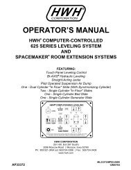
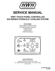
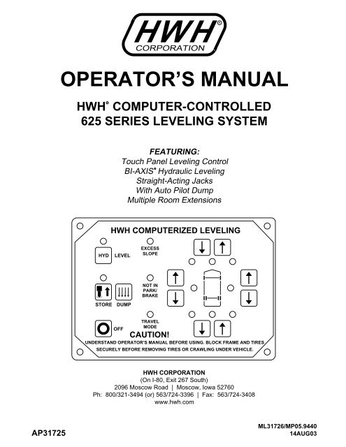
OPERATOR’S MANUAL<br />
<strong>HWH</strong> COMPUTER-CONTROLLED<br />
625 SERIES LEVELING SYSTEM<br />
R<br />
FEATURING:<br />
Touch Panel Leveling Control<br />
R<br />
BI-AXIS Hydraulic Leveling<br />
Straight-Acting Jacks<br />
With Auto Pilot Dump<br />
Multiple Room Extensions<br />
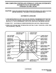
<strong>HWH</strong> COMPUTERIZED LEVELING<br />
HYD<br />
LEVEL<br />
EXCESS<br />
SLOPE<br />
STORE<br />
DUMP<br />
NOT IN<br />
PARK/<br />
BRAKE<br />
TRAVEL<br />
MODE<br />
OFF<br />
CAUTION!<br />
UNDERSTAND OPERATOR’S MANUAL BEFORE USING. BLOCK FRAME AND TIRES<br />
SECURELY BEFORE REMOVING TIRES OR CRAWLING UNDER VEHICLE.<br />
<strong>HWH</strong> CORPORATION<br />
(On I-80, Exit 267 South)<br />
2096 Moscow Road | Moscow, Iowa 52760<br />
Ph: 800/321-3494 (or) 563/724-3396 | Fax: 563/724-3408<br />
www.hwh.com<br />
AP31725<br />
<strong>ML31726</strong>/MP05.9440<br />
14AUG03
OPERATOR’S MANUAL<br />
CAUTION !<br />
READ THE ENTIRE OPERATOR MANUAL BEFORE OPERATING.<br />
BLOCK FRAME AND TIRES SECURELY BEFORE CRAWLING UNDER VEHICLE. DO NOT USE LEVELING JACKS OR<br />
AIR SUSPENSION TO SUPPORT VEHICLE WHILE UNDER VEHICLE OR CHANGING TIRES. VEHICLE MAY DROP<br />
AND/OR MOVE FORWARD OR BACKWARD WITHOUT WARNING CAUSING INJURY OR DEATH.<br />
KEEP ALL PEOPLE CLEAR OF VEHICLE WHILE OPERATING LEVELING SYSTEM OR ROOM EXTENSIONS.<br />
KEEP ALL PEOPLE CLEAR OF VEHICLE WHILE DUMPING AIR FROM THE VEHICLE’S SUSPENSION.<br />
DO NOT MOVE THE VEHICLE IF THE VEHICLE IS NOT AT THE PROPER RIDE HEIGHT. CONTACT MANUFACTURER<br />
TECHNICAL SERVICE FOR MOVING THE VEHICLE WHEN NOT AT THE PROPER RIDE HEIGHT.<br />
WEAR SAFETY GLASSES WHEN INSPECTING OR SERVICING THE SYSTEM TO PROTECT EYES FROM DIRT, METAL<br />
CHIPS, OIL LEAKS, ETC. FOLLOW ALL OTHER APPLICABLE SHOP SAFETY PRACTICES.<br />
IMPORTANT: IF COACH IS EQUIPPED WITH A ROOM EXTENSION, READ ROOM EXTENSION SECTION BEFORE<br />
OPERATING LEVELING SYSTEM.<br />
HOW TO OBTAIN WARRANTY SERVICE<br />
THIS IS NOT TO BE INTERPRETED AS A STATEMENT OF WARRANTY<br />
<strong>HWH</strong> CORPORATION strives to maintain the highest level of<br />
customer satisfaction. Therefore, if you discover a defect or<br />
problem, please do the following:<br />
FIRST: Notify the dealership where you purchased the<br />
vehicle or had the leveling system installed. Dealership<br />
management people are in the best position to resolve<br />
the problem quickly. If the dealer has difficulty solving<br />
the problem, he should immediately contact the Customer<br />
Service Department, at <strong>HWH</strong> CORPORATION.<br />
SECOND: If your dealer cannot or will not solve the problem,<br />
notify the Customer Service Department:<br />
<strong>HWH</strong> CORPORATION 2096 Moscow Rd. Moscow IA. 52760<br />
(563) 724-3396 OR (800) 321-3494. Give your name and<br />
address, coach manufacturer and model year, date the<br />
coach was purchased, or the date of system installation,<br />
description of the problem, and where you can be reached<br />
during business hours (8:00 a.m. till 5:00 p.m. c.s.t.).<br />
<strong>HWH</strong> CORPORATION personnel will contact you to<br />
determine whether or not your claim is valid. If it is, <strong>HWH</strong><br />
CORPORATION will authorize repair or replacement of the<br />
defective part, either by appointment at the factory or by the<br />
authorization of an independent service facility, to be<br />
determined by <strong>HWH</strong> CORPORATION. All warranty repairs<br />
must be performed by an independent service facility<br />
authorized by <strong>HWH</strong> CORPORATION, or at the<br />
<strong>HWH</strong> CORPORATION factory, unless prior written approval<br />
has been obtained from proper <strong>HWH</strong> CORPORATION<br />
personnel.<br />
MP15.9800<br />
08FEB06
CONTROL IDENTIFICATION<br />
625 SERIES LEVELING SYSTEM<br />
COMPUTER-CONTROL<br />
"NOT IN PARK" LIGHT<br />
ON LIGHT<br />
"LEVEL" (HYD) BUTTON<br />
"EXCESS SLOPE"<br />
LIGHT<br />
<strong>HWH</strong> COMPUTERIZED LEVELING<br />
HYD LEVEL<br />
EXCESS<br />
SLOPE<br />
FRONT RETRACT BUTTON<br />
FRONT EXTEND BUTTON<br />
WARNING LIGHTS<br />
(4- Red)<br />
STORE LIGHT<br />
"STORE" BUTTON<br />
"DUMP" BUTTON<br />
STORE DUMP<br />
OFF<br />
NOT IN<br />
PARK/<br />
BRAKE<br />
TRAVEL<br />
MODE<br />
CAUTION!<br />
UNDERSTAND OPERATOR’S MANUAL BEFORE USING. BLOCK FRAME AND TIRES<br />
SECURELY BEFORE REMOVING TIRES OR CRAWLING UNDER VEHICLE.<br />
RIGHT SIDE EXTEND BUTTON<br />
RIGHT SIDE RETRACT BUTTON<br />
LEVELING LIGHTS<br />
(4- Yellow)<br />
"OFF" BUTTON<br />
REAR EXTEND BUTTON<br />
"TRAVEL MODE" LIGHT<br />
LEFT SIDE EXTEND<br />
BUTTON<br />
LEFT SIDE RETRACT<br />
BUTTON<br />
REAR RETRACT BUTTON<br />
CONTROL FUNCTIONS<br />
"OFF" BUTTON:<br />
operation.<br />
CONTROL BUTTONS<br />
Push the "OFF" button to stop hydraulic<br />
"LEVEL" (HYD) BUTTON: This is the on button and<br />
automatic operation button. The ON indicator light is above<br />
the "HYD" button.<br />
"STORE" BUTTON: The store indicator light is above the<br />
"STORE" button. This button is used to automatically retract<br />
the jacks.<br />
"DUMP" BUTTON: This is a manual button for dumping air<br />
from the vehicle suspension.<br />
EXTEND BUTTONS (UP ARROWS): These buttons will<br />
extend their respective jack pairs to lift the vehicle.<br />
RETRACT BUTTONS (DOWN ARROWS): These buttons<br />
will retract their respective jack pairs to lower the vehicle.<br />
INDICATOR LIGHTS<br />
LEVELING LIGHTS: The four yellow indicating lights are<br />
level sensing indicators. When a yellow light is on, it<br />
indicates that its side, end, or corner of the vehicle is low.<br />
No more than two lights should be on at the same time.<br />
WARNING LIGHTS: The four red lights surrounding the<br />
yellow level indicators are jacks down WARNING lights.<br />
They are functional only when the ignition is in the "ON"<br />
or "ACC" position, the system is on, and the jacks are<br />
extended 1/4 to 1/2 inch.<br />
"EXCESS SLOPE" LIGHT: This indicator will light when<br />
the leveling system cannot level the vehicle.<br />
"NOT IN PARK/BRAKE" LIGHT: This indicator will light<br />
when the hand/auto brake is not set and the "LEVEL"<br />
button is being pushed.<br />
"TRAVEL MODE" LIGHT: This indicator light will be on<br />
when the ignition is on, when the jacks are retracted and<br />
there are no red WARNING lights on.<br />
MASTER "JACKS DOWN" WARNING LIGHT: This is a<br />
light mounted in the dash separate from the touch panel.<br />
It will be on when any one or more jacks are extended<br />
and the ignition is "ON".<br />
BUZZER: This is a jacks down warning. It will sound if the<br />
master "JACKS DOWN" warning light is on.<br />
MP25.3043<br />
12JUN03
CONTROL IDENTIFICATION<br />
PUMP RUN TIME<br />
SYSTEM VARIATIONS FOR PUMP RUN TIME<br />
PUMP RUN TIME<br />
Pump motors used with <strong>HWH</strong> leveling systems and room extension systems come in 3 different diameters; 3", 3.7" and 4.5".<br />
Contact the vehicle manufacturer or <strong>HWH</strong> for help with identifying the motor size. It is important that any time the pump<br />
runs for more than four minutes with a 3" motor; or six minutes with a 3.7" or 4.5" motor that the motor is allowed<br />
to cool for thirty minutes before continuing. Continuous operation of the pump motor without allowing the motor<br />
to cool can damage the motor. For cold weather information see "COLD WEATHER OPERATIONS" below.<br />
The <strong>HWH</strong> systems with a computer processor monitor the pump run time and will turn the pump off if the run time exceeds a<br />
specified time. This time can vary with different systems. Due to available electronics or system design, the pump run time<br />
programs will also vary. Leveling systems and room extensions that are not controlled by a system processor have no pump<br />
run time protection. DO NOT run the pump more than four or six minutes without allowing the pump motor to cool for<br />
thirty minutes.<br />
Some systems with rooms run the rooms separate from the system processor. These systems do not monitor pump<br />
run time when operating the rooms. DO NOT run the pump more than four or six minutes without allowing the<br />
pump motor to cool for thirty minutes.<br />
Some systems can be turned back on immediately after the processor turns the pump off. DO NOT turn the system<br />
back on or run the pump without allowing the pump motor to cool for thirty minutes.<br />
When operating some leveling systems manually or operating the room extensions, the pump will turn off and back<br />
on while pushing the control button when the pump run time has been exceeded. DO NOT continue without allowing<br />
the pump motor to cool for thirty minutes.<br />
With some systems, when the processor has turned the pump off because the run time has been exceeded, power<br />
to the <strong>HWH</strong> system must be turned off and back on before the system will operate. With motorized vehicles, turn the<br />
ignition off and back on. With non-motorized vehicles, turn the master power switch for the <strong>HWH</strong> system off and back<br />
on. DO NOT continue without allowing the pump motor to cool for thirty minutes.<br />
Some <strong>HWH</strong> systems are equipped with a lighted reset switch.<br />
If the processor turns the pump off because the run time has<br />
been exceeded, the light in the reset switch will turn on. The<br />
system will not operate until the reset switch is pushed.<br />
DO NOT continue without allowing the pump motor to<br />
cool for thirty minutes.<br />
LIGHTED RESET SWITCH<br />
No matter what <strong>HWH</strong> system is on the vehicle, the pump should not be ran for more than four minutes<br />
(3" motors) or six minutes (3.7" or 4.5" motors) without allowing the pump motor to cool for thirty minutes.<br />
Continuous operation of the pump motor without allowing the motor to cool can damage the pump motor.<br />
Contact <strong>HWH</strong> corporation to get specific information about the system in this vehicle.<br />
COLD WEATHER OPERATIONS<br />
<strong>HWH</strong> leveling and room extension systems are designed to function in cold weather down to 0 degrees Fahrenheit. Below<br />
freezing (32 degrees Fahrenheit) the jacks or rooms will operate slower than usual.<br />
For operation in temperatures dropping below -20 degrees Fahrenheit, it is necessary that the system is equipped with oil<br />
designed for extreme cold weather application such as a synthetic oil. (Contact <strong>HWH</strong> for recommendations.)<br />
DO NOT run the pump motor continuously. It is important that any time the pump runs for more than four minutes<br />
with a 3" motor; or six minutes with a 3.7" or 4.5" motor that the motor is allowed to cool for thirty minutes before<br />
continuing. Continuous operation of the pump motor without allowing the motor to cool can damage the motor.<br />
Continuous operation of the pump with slow moving jacks or rooms in cold weather, without allowing the pump motor to<br />
cool will cause the pump motor to burn up and damage the pump assembly.<br />
MP25.9995<br />
14MAR12
OPERATING PROCEDURES<br />
GENERAL INSTRUCTIONS<br />
Maintain adequate clearance in all directions for vehicle, room<br />
extensions, awnings, doors, steps, etc. Vehicle may move in<br />
any direction due to jacks extending or retracting, settling of<br />
the jacks or the vehicle, equipment malfunction, etc..<br />
If parking on soft ground or asphalt paving, a wood block or<br />
pad should be placed under each jack.<br />
If the hand / auto brake is not set when the "HYD" button<br />
is pressed, the "NOT IN PARK/BRAKE" light will come on.<br />
When the "HYD" button is released the "NOT IN PARK/<br />
BRAKE" light will go out. The panel will NOT turn on.<br />
CAUTION: DO NOT MOVE THE VEHICLE IF ONE<br />
OR MORE JACKS ARE EXTENDED TO THE GROUND.<br />
Press the "OFF" button or turn the ignition switch "OFF" at<br />
any time to stop the operation of the system.<br />
Any time a hydraulic leveling process is interrupted, retract<br />
the jacks according to the JACK RETRACTION Section and<br />
then restart the leveling process.<br />
PREPARATION FOR TRAVEL<br />
Before traveling, the red jack warning lights must be off<br />
and the "TRAVEL MODE" light must be on. If lights are<br />
not correct for travel, retract jack as described in the<br />
JACK RETRACTION Section.<br />
If the jacks are retracted but a red "WARNING" light is lit<br />
or the green "TRAVEL MODE" light is not lit, the system<br />
needs to be serviced.<br />
Any room extension or generator slide should be fully<br />
retracted before traveling.<br />
CAUTION: DO NOT MOVE THE VEHICLE WHILE<br />
THE LEVELING JACKS ARE STILL IN CONTACT WITH<br />
THE GROUND OR IN THE EXTEND POSITION. THIS<br />
VEHICLE IS EQUIPPED WITH STRAIGHT-ACTING JACKS.<br />
MOVING THE VEHICLE WITH THE LEVELING JACKS<br />
EXTENDED CAN CAUSE SEVER DAMAGE TO THE JACKS<br />
AND OR THE VEHICLE AND CREATE A DRIVING<br />
HAZARD. DO NOT RELY SOLELY UPON WARNING<br />
LIGHTS. IT IS THE OPERATOR’S RESPONSIBILITY<br />
TO CHECK THAT ALL JACKS ARE FULLY RETRACTED<br />
INTO THE STORE/TRAVEL POSITION AND THE<br />
VEHICLE IS AT THE PROPER RIDE HEIGHT FOR<br />
TRAVELING. CONTACT MANUFACTURER TECHNICAL<br />
SERVICE BEFORE MOVING A VEHICLE THAT IS NOT<br />
AT PROPER TRAVEL HEIGHT.<br />
IMPORTANT: Any time the "HYD" button has been<br />
pushed, push the "STORE" button before traveling.<br />
If the jacks cannot be retracted according to the JACK<br />
RETRACTION Section, retract the jacks according to the<br />
MANUAL JACK RETRACTION Section. The system<br />
should then be checked.<br />
MP35.3811<br />
19NOV07
OPERATING PROCEDURES<br />
625 SERIES LEVELING SYSTEM<br />
AUTOMATIC HYDRAULIC LEVELING<br />
1. Place transmission in the recommended position for<br />
parking vehicle and set parking brake. Turn the coach<br />
engine off. Turn the ignition to the "ACCESSORY" position.<br />
2. Press the "LEVEL" button to enter the hydraulic<br />
operation mode. The ON light will glow steady.<br />
3. At this time, the operator may want to check the jacks<br />
and place a pad under each jack if the ground will not<br />
support the vehicle.<br />
4. Press the "LEVEL" button a second time.<br />
The ON light will start to flash.<br />
NOTE: After pushing the "LEVEL" button a second time,<br />
the system will begin to dump air from the vehicle<br />
suspension. After approximately 25 seconds, the<br />
leveling process will begin.<br />
The system will automatically extend the jacks to level the<br />
vehicle and then extend any remaining jacks for stabilizing.<br />
After the system has finished leveling and stabilizing, and has<br />
completed the air dump cycle, it will automatically shut off.<br />
EXCESS SLOPE SITUATION: In the event the jacks are<br />
unable to level the coach, the "EXCESS SLOPE" light will<br />
come on. Excess slope is two jacks fully extending without<br />
turning the yellow level light out. The system will not stabilize<br />
the vehicle if the "EXCESS SLOPE" light comes on. One or<br />
more jacks may not be extended. The system will shut off<br />
leaving the "EXCESS SLOPE" light on. The "EXCESS<br />
SLOPE" light will remain on if the ignition is in the "ON" or<br />
"ACC" position, until the jacks have been fully retracted<br />
turning the red warning lights out. Push the "STORE" button<br />
to retract the jacks. Move the vehicle to a more level position<br />
or level the vehicle as close as possible according to the<br />
MANUAL HYDRAULIC OPERATION section.<br />
5. Turn the ignition switch to the "OFF" position.<br />
CAUTION:<br />
THE OPERATOR MUST BE SURE THAT<br />
THERE ARE NO OBJECTS UNDER THE VEHICLE AND THAT<br />
ALL PEOPLE ARE CLEAR OF THE VEHICLE.<br />
1. Start the engine. Store the jacks immediately.<br />
NOTE: When the jacks are stored with the ignition in<br />
the ON position, the warning buzzer will sound until<br />
the jacks have retracted to the STORE position. If<br />
desired, the jacks can be stored with the ignition key<br />
in the accessory position. This will eliminate the<br />
warning buzzer while the jacks are retracting.<br />
2. Press the "STORE" button. The store indicator light will<br />
flash. The vehicle suspension will start to return to ride<br />
height. The front jacks will retract for 2 seconds before the<br />
rear jacks will begin to retract. As each jack retracts, its red<br />
WARNING light will go out. The system will automatically<br />
shut down six minutes after the four individual red<br />
"WARNING" lights are out. If any one red "WARNING light<br />
does not go out, the system will continue to store for thirty<br />
minutes, then shut down regardless of the "WARNING"<br />
lights condition.<br />
JACK RETRACTION<br />
CAUTION: DO NOT MOVE THE VEHICLE WHILE THE<br />
LEVELING JACKS ARE STILL IN CONTACT WITH THE GROUND<br />
OR IN THE EXTEND POSITION. THIS VEHICLE IS EQUIPPED<br />
WITH STRAIGHT-ACTING JACKS. MOVING THE VEHICLE<br />
WITH THE LEVELING JACKS EXTENDED CAN CAUSE<br />
SEVERE DAMAGE TO THE JACKS AND OR THE VEHICLE AND<br />
CREATE A DRIVING HAZARD. DO NOT RELY SOLELY UPON<br />
WARNING LIGHTS. IT IS THE OPERATOR’S RESPONSIBILITY TO<br />
CHECK THAT ALL JACKS ARE FULLY RETRACTED INTO<br />
THE STORE/TRAVEL POSITION AND THE VEHICLE IS AT<br />
THE PROPER RIDE HEIGHT.<br />
3. The vehicle can be moved as soon as the red warning<br />
lights are out, the jacks are in the STORE/TRAVEL position,<br />
the green "TRAVEL" light is on, and the suspension air bags<br />
are inflated to the vehicles proper ride height.<br />
IMPORTANT: If a red warning light and buzzer come on<br />
while traveling, the jacks should be checked as soon as<br />
a safe parking location is found.<br />
4. If jacks cannot be retracted by the above procedure see<br />
MANUAL JACK RETRACTION Section.<br />
NOTE: When traveling thermal expansion may cause<br />
a jack to extend slightly. When the "STORE" button<br />
has been used to retract the jacks, the system will<br />
automatically retract any jack that extends due to<br />
thermal expansion.<br />
IMPORTANT: Pushing the "OFF" button or turning the<br />
ignition key will stop the STORE procedure. Any time<br />
the STORE procedure is stopped before all 4 red Warning<br />
Lights go out, the jacks should be completely retracted<br />
by pushing the "STORE" button before traveling.<br />
NOTE: If the vehicle is parked or stored with the jacks<br />
extended for an extended period of time and the jacks<br />
fail to retract completely, extend the jacks back down<br />
to the ground then retract the jacks again.<br />
MP35.3815<br />
01JUL05
OPERATING PROCEDURES<br />
MANUAL HYDRAULIC OPERATION<br />
1. Place transmission in the recommended position for parking<br />
the vehicle, and set the parking brake. Turn the ignition to the<br />
"ACCESSORY" position.<br />
2. Press the "HYD" button. The indicator light will glow steady.<br />
3. Place pads under the jack feet if the ground will not support<br />
the vehicle on the jacks.<br />
4. Push the "DUMP" button. Wait until all of the air is<br />
exhausted from the vehicles suspension system.<br />
5. The vehicle may be leveled using the manual EXTEND<br />
(UP ARROW) buttons on the right half of the panel. If a yellow<br />
LEVEL SENSING light is on, that side or end of the vehicle is<br />
low. It is best to level the vehicle side to side first, if needed,<br />
before front to rear.<br />
Jacks will extend (or retract) in pairs to raise (or lower) a side<br />
or end of the vehicle. Any jack not used for leveling can be<br />
extended to the ground. This provides additional stability<br />
against wind and activity in the vehicle. Jacks used to<br />
stabilize the vehicle after leveling is complete should lift the<br />
vehicle slightly after touching the ground.<br />
IMPORTANT: Do not continue to push an EXTEND<br />
button for more than ten (10) seconds after that pair of<br />
jacks are fully extended.<br />
6. When leveling is completed, push the "OFF" button on the<br />
touch panel and turn the ignition switch to the "OFF" position.<br />
IMPORTANT: Push the "STORE" button before traveling<br />
when manual operation of the leveling system is used.<br />
MP35.3840<br />
03SEP09
OPERATING PROCEDURES<br />
MANUAL JACK RETRACTION<br />
MANUAL JACK RETRACTION<br />
WARNING:KEEP AWAY FROM THE WHEELS,<br />
DO NOT CRAWL UNDER THE VEHICLE, KEEP A SAFE<br />
DISTANCE IN FRONT AND REAR OF THE VEHICLE.<br />
THE VEHICLE MAY DROP AND/OR MOVE FORWARD<br />
OR BACKWARD WITHOUT WARNING AS THE VALVE<br />
RELEASE IS OPERATED.<br />
IMPORTANT: <strong>HWH</strong> recommends that all <strong>HWH</strong> room<br />
extensions are fully retracted prior to performing<br />
manual jack retraction procedures.<br />
Use the manual valve release for retracting the jacks only<br />
if the STORE feature on the <strong>HWH</strong> control panel will not<br />
retract the jacks.<br />
1. Locate your power unit-manifold assembly.<br />
(The diagram below represents a typical Power Unit-<br />
Manifold Assembly it may not be an exact match to yours).<br />
NOTE: Multiple manifolds may be present on the<br />
power unit. The upper most manifold should control<br />
jack functions. (Valve styles and arrangements will vary)<br />
2. Allow clearance for the vehicle to lower.<br />
3. Using the diagram below identify the style<br />
of your two center valves.<br />
NOTE: As of APRIL 2002 a 1/4" Nut Driver has been<br />
incorporated into the Breather Cap. Before using read<br />
and understand the last page of this manual.<br />
Large style with T-Handle valve release: The T-Handle<br />
will turn several turns easily. As the valve starts to open,<br />
the T-Handle will turn harder. Make sure the valves have<br />
been opened far enough to allow the jacks to retract.<br />
Small style with Valve Release Nut: DO NOT turn the<br />
1/4" valve release nut more than 4 and 1/2 turns. Turning<br />
the nut more could damage the valve.<br />
Large style with Valve Release Nut: The 1/4" Valve<br />
release nut is located under a plastic plug that must be<br />
removed to gain access. Open valve 1-1/2 to 2 full turns.<br />
DO NOT turn the 1/4" valve release nut more than<br />
2 full turns. Turning the nut more could damage the<br />
valve. Replace the protective plastic plug.<br />
4. Retract the front jacks by opening the two center valves.<br />
Slowly turn the manual valve releases counter clockwise<br />
until the jacks start to retract.<br />
5. Repeat the process by identifying then opening<br />
the two outer valves, if applicable.<br />
6. Check that all jacks are now retracted. If yes, continue.<br />
If no, notify the dealership where you purchased the vehicle<br />
or had the leveling system installed or contact<br />
<strong>HWH</strong> <strong>Corporation</strong> customer service.<br />
7. Close the valves by turning each valve release clockwise.<br />
IMPORTANT: Once the manual valve release is snug,<br />
DO NOT tighten the manual valve release past this<br />
point as internal damage may occur to the solenoid.<br />
8. The system should now be repaired before using again.<br />
LARGE STYLE<br />
WITH T-HANDLE<br />
VALVE RELEASE<br />
MANIFOLD<br />
SMALL STYLE<br />
WITH VALVE<br />
RELEASE NUT<br />
BREATHER<br />
CAP<br />
PLASTIC PLUG<br />
MP35.601G<br />
LARGE STYLE<br />
WITH VALVE<br />
RELEASE NUT<br />
POWER UNIT-MANIFOLD ASSEMBLY<br />
MP35.384N<br />
01MAR10
OPERATING PROCEDURES<br />
ROOM EXTEND PROCEDURE<br />
NOTE: The park brake must be set before a room can be<br />
extended or retracted.<br />
CAUTION: OPERATING A ROOM WITH ANY<br />
ROOM LOCKING, CLAMPING OR MANUAL RETRACTING<br />
DEVICES ATTACHED OR ENGAGED CAN CAUSE<br />
PERSONAL INJURY AND VEHICLE DAMAGE. IT IS THE<br />
OPERATOR’S RESPONSIBILITY TO ENSURE THAT<br />
ALL ROOM LOCKING, CLAMPING OR MANUAL<br />
RETRACTING DEVICES ARE DETACHED OR<br />
DISENGAGED BEFORE OPERATING THE ROOM.<br />
It is recommended to complete the Leveling Procedure<br />
before operating room extensions.<br />
1. Level the vehicle using the hydraulic leveling system.<br />
2. Unlock all room-locking devices.<br />
NOTE: If the MANUAL RETRACT WINCH is attached to<br />
the room remove it before extending the room.<br />
CAUTION:<br />
KEEP PEOPLE AND OBSTRUCTIONS<br />
CLEAR OF ROOM WHEN OPERATING.<br />
3. To extend the room, press and hold the<br />
ROOM CONTROL SWITCH in the "EXTEND" position<br />
until the room is fully extended.<br />
NOTE: Hold the switch to "EXTEND" three or four seconds<br />
after the room is fully extended. This assures proper<br />
pressurization of the cylinders. During normal operation<br />
of the room, do not reverse direction of the room until<br />
the room is fully extended. If necessary, the direction<br />
of the room may be reversed, but watch for binding of<br />
the room. If the direction of the room has been<br />
reversed, DO NOT re-extend the room until the room<br />
has been fully retracted.<br />
IMPORTANT: Do not hold the ROOM CONTROL SWITCH<br />
in the "EXTEND" position for more than ten seconds<br />
after the room is fully extended or stops moving.<br />
If either side of the room stops moving, release the<br />
room control switch immediately. DO NOT force the<br />
room. DO NOT reverse direction of the room, contact<br />
<strong>HWH</strong> Customer Service for assistance 1-800-321-3494.<br />
NOTE: Releasing the ROOM CONTROL SWITCH will<br />
halt the operation of the room.<br />
NOTE: Make sure there is adequate clearance to fully<br />
extend the room.<br />
ROOM RETRACT PROCEDURE<br />
NOTE: The park brake must be set before a room can be<br />
extended or retracted.<br />
CAUTION: KEEP PEOPLE AND OBSTRUCTIONS<br />
CLEAR OF ROOM WHEN OPERATING.<br />
It is recommended to retract room extensions<br />
before retracting jacks.<br />
1. To retract the room press and hold the<br />
ROOM CONTROL SWITCH in the "RETRACT" position<br />
until the room is fully retracted.<br />
NOTE: Hold the switch to "RETRACT" three or four seconds<br />
after the room is fully retracted. This assures proper<br />
pressurization of the cylinders. During normal operation<br />
of the room, do not reverse direction of the room until<br />
the room is fully retracted. If necessary, the direction<br />
of the room may be reversed, but watch for binding of<br />
the room. If the direction of the room has been<br />
reversed, DO NOT retract the room until the room<br />
has been fully extended.<br />
IMPORTANT: Do not hold the ROOM CONTROL SWITCH<br />
in the "RETRACT" position for more than ten seconds<br />
after the room is fully retracted or stops moving.<br />
If either side of the room stops moving, release the<br />
room control switch immediately. DO NOT force the<br />
room. DO NOT reverse direction of the room, contact<br />
<strong>HWH</strong> Customer Service for assistance 1-800-321-3494.<br />
NOTE: Releasing the ROOM CONTROL SWITCH will<br />
halt the operation of the room.<br />
2. Engage all room-locking devices.<br />
3. If the room will not retract see the MANUAL ROOM<br />
RETRACT PROCEDURE.<br />
IMPORTANT: Room-locking devices should be locked<br />
while traveling.<br />
MP35.9300<br />
24APR03
MANUAL ROOM AND GENERATOR SLIDE RETRACT PROCEDURE<br />
(WITH SOLENOID VALVES WITH VALVE RELEASE NUTS)<br />
(USE ONLY WHEN THE ROOM WILL NOT RETRACT WITH THE ROOM CONTROL SWITCH)<br />
OVERVIEW<br />
The room can be retracted manually if a hydraulic or electric<br />
failure prevents the room from being retracted using the<br />
CONTROL SWITCH. For normal retract sequence see the<br />
ROOM SLIDE RETRACT PROCEDURES. Refer to the<br />
vehicle manufacturer for storage location of the winch<br />
and information for connecting the winch to the room.<br />
IMPORTANT: If the vehicle is not equipped with a winch,<br />
DO NOT use other pulling devices to retract the room.<br />
Follow steps 2 and 3 and try pushing the room in.<br />
Contact the vehicle manufacturer or <strong>HWH</strong> Customer<br />
Service at 1-800-321-3494 or 563-724-3396 for assistance.<br />
CAUTION: THE MANUAL RETRACT WINCH IS<br />
EQUIPPED FOR MANUALLY RETRACTING THE ROOM<br />
ONLY. IT IS NOT TO BE USED FOR LIFTING OR ANY<br />
OTHER APPLICATION. HIGH FORCES ARE CREATED<br />
WHEN USING A WINCH, CREATING POTENTIAL SAFETY<br />
HAZARDS. FAILURE TO FOLLOW ALL CAUTIONS AND<br />
INSTRUCTIONS MAY CAUSE FAILURE OF THE MANUAL<br />
RETRACT WINCH OR CONNECTIONS RESULTING IN<br />
DAMAGE OR PERSONAL INJURY. MAINTAIN FIRM GRIP<br />
ON THE WINCH HANDLE AT ALL TIMES. NEVER<br />
RELEASE THE HANDLE WHEN RATCHET LEVER IS IN<br />
THE OFF POSITION AND THE WINCH IS LOADED. THE<br />
WINCH HANDLE COULD SPIN VIOLENTLY AND CAUSE<br />
PERSONAL INJURY. CHECK THE WINCH AND STRAPS<br />
FOR DAMAGE OR WEAR, AND CHECK FOR PROPER<br />
RATCHET OPERATION ON EACH USE OF THE WINCH.<br />
DO NOT USE IF DAMAGED OR WORN.<br />
1. Retract jacks following the LEVELING SYSTEM<br />
RETRACT PROCEDURE.<br />
NOTE : When manually retracting the room, make sure<br />
the jacks are retracted before retracting the room.<br />
2. Locate the HYDRAULIC PUMP/MANIFOLD unit.<br />
SOLENOID VALVES<br />
VALVE<br />
RELEASE<br />
NUT<br />
VALVE<br />
RELEASE<br />
NUT<br />
HYDRAULIC PUMP/MANIFOLD<br />
LEVELING SYSTEM MANIFOLD NOT SHOWN<br />
3. Open the Solenoid Valves by slowly turning the valve<br />
release nuts counter clockwise using the 1/4" nut driver<br />
supplied.<br />
IMPORTANT: Only open the valves enough to retract<br />
the room. DO NOT turn the release nuts more than<br />
4 and 1/2 turns. Turning the nuts more could damage<br />
the valves.<br />
NOTE: Prior to APRIL 2002 a 1/4" Nut Driver was sent<br />
with the Operators Manual. As of APRIL 2002 the<br />
1/4" Nut Driver has been incorporated into the Breather<br />
Cap. See the back page of this manual for further info.<br />
NOTE: The room may move slightly as the SOLENOID<br />
VALVES are opened and internal pressure is released.<br />
4. Locate the MANUAL RETRACT WINCH and connect<br />
it to the room according to the vehicle manufacturer’s<br />
instructions. To extend the WINCH STRAP firmly grasp<br />
WINCH HANDLE, place RATCHET LEVER in its OFF<br />
position, and slowly rotate the WINCH HANDLE<br />
counter clockwise, keeping a firm grip on the handle. When<br />
enough WINCH STRAP is extended, place the RATCHET<br />
LEVER in its ON position and slowly rotate the WINCH<br />
HANDLE clockwise until the RATCHET LEVER locks.<br />
ON<br />
OFF<br />
WINCH STRAP<br />
RATCHET LEVER<br />
WINCH HANDLE<br />
MANUAL RETRACT WINCH<br />
WINCH<br />
HOOK<br />
5. Slowly winch the room in by turning the WINCH HANDLE<br />
clockwise. The RATCHET LEVER should produce a loud, sharp,<br />
clicking noise.<br />
NOTE: Winching the room in quickly will raise pressure<br />
in the hydraulic fluid and make winching more difficult.<br />
CAUTION:<br />
OPERATE THE MANUAL RETRACT<br />
WINCH BY HAND POWER ONLY. IF THE WINCH<br />
CANNOT BE CRANKED EASILY WITH ONE HAND IT IS<br />
PROBABLY OVERLOADED. IF WINCHING BECOMES<br />
TOO DIFFICULT STOP AND CHECK FOR OBSTRUCTIONS<br />
OR RESTRICTIONS ON THE ROOM AND ROOM<br />
EXTENSION MECHANISM.<br />
6. When the room is fully retracted, engage the room locking<br />
devices. Leave the retract winch engaged and the solenoid<br />
valves open.<br />
CAUTION: THE ROOM EXTENSION SOLENOID<br />
VALVE RELEASE NUTS MUST BE IN THE OPEN<br />
POSITION WHEN THE MANUAL RETRACT WINCH IS<br />
ENGAGED.<br />
7. The system should be repaired before using again.<br />
NOTE: After repairs are made, when<br />
closing the VALVE RELEASE NUTS, do<br />
not over tighten the nuts.<br />
MP35.952D<br />
01MAY02
OPERATING PROCEDURES<br />
"LEVEL-OUT" (ANGLE MOUNT) ROOM EXTENSION MECHANISM<br />
MANUAL ROOM RETRACTION PROCEDURES<br />
IMPORTANT: READ THESE INSTRUCTIONS<br />
THOROUGHLY BEFORE ATTEMPTING TO USE<br />
THE MANUAL RETRACT BOLTS TO RETRACT<br />
THE ROOM.<br />
1. Determine which extend and retract solenoid valves are<br />
assigned to the room. Manually open the valve release nuts<br />
for the extend and retract solenoid valves by turning the 1/4"<br />
release nuts counter clockwise 4 and 1/2 turns. Turning the<br />
nuts more could damage the valves. If necessary, open all<br />
valves on the pump/manifold arrangement. There are 4<br />
valves for the leveling system (if applicable) and 2 valves<br />
for each <strong>HWH</strong> room extension.<br />
NOTE: The breather cap dip stick is also a 1/4" nut driver.<br />
2. Gain access to the 13/16" Manual Retraction Bolts (one<br />
on each mechanism) by raising the STORE-MORE access<br />
panel.<br />
3. Remove the Thumb Screws (one on each mechanism)<br />
completely by turning them counterclockwise.<br />
4. Using wrench provided, a personal wrench or a tire iron<br />
with a 13/16" or 21mm opening rotate either mechanism’s<br />
Manual Retraction Bolt clockwise 6 complete turns.<br />
5. Move to the second room extension mechanism, rotate<br />
the Manual Retraction Bolt clockwise 12 complete turns.<br />
6. Return to the first room extension mechanism and rotate<br />
the Manual Retraction Bolt clockwise 12 complete turns.<br />
8. Replace both Thumb Screws. Leave the manual valve<br />
releases open.<br />
IMPORTANT: If at any stage something is not<br />
understood or if the room begins to bind DO NOT force<br />
the room, contact <strong>HWH</strong> Customer Service for assistance<br />
1-800-321-3494.<br />
IMPORTANT: DO NOT EXTEND THE ROOM<br />
UNTIL THE STEPS BELOW HAVE BEEN<br />
COMPLETED!<br />
1. Gain access to the 13/16" Manual Retraction Bolts (one<br />
on each mechanism) by raising the STORE-MORE access<br />
panel.<br />
2. Remove the Thumb Screws (one on each mechanism)<br />
completely by turning them counterclockwise.<br />
3. If needed, using wrench provided, a personal wrench or<br />
a tire iron with a 13/16" or 21mm opening rotate either<br />
mechanism’s Manual Retraction Bolt counterclockwise until<br />
resistance is met.<br />
4. Move to the second room extension mechanism and<br />
repeat step 3.<br />
5. Replace both Thumb Screws.<br />
6. Close both manual valve releases assigned to the<br />
room. Turn the valve release nuts clockwise until snug.<br />
DO NOT over tighten.<br />
7. Repeat steps 4 and 5 alternating from mechanism to<br />
mechanism rotating each Manual Retraction Bolt 12<br />
complete turns until room is sealed. (DO NOT EXCEED 15<br />
FT.LBS. FORCING THE MANUAL RETRACT BOLT MAY<br />
DAMAGE THE MANUAL RETRACT MECHANISM.) Make<br />
sure the room does not bind.<br />
SOLENOID VALVES<br />
(2 FOR EACH ROOM)<br />
VALVE<br />
RELEASE<br />
NUT<br />
VALVE<br />
RELEASE<br />
NUT<br />
BREATHER<br />
CAP-DIP<br />
STICK<br />
HYDRAULIC PUMP/MANIFOLD<br />
LEVELING SYSTEM MANIFOLD NOT SHOWN<br />
Thumb Screw<br />
Actual Mounting May Differ<br />
Manual Retraction Bolt<br />
MP35.953C<br />
01JUN07
OPERATING PROCEDURES<br />
"LEVEL-OUT" ROOM EXTENSION MECHANISM<br />
MANUAL ROOM RETRACTION PROCEDURES<br />
1. Determine which extend and retract solenoid valves are<br />
assigned to the room. Manually open the valve release nuts<br />
for the extend and retract solenoid valves by turning the 1/4"<br />
release nuts counter clockwise 4 and 1/2 turns. Turning the<br />
nuts more could damage the valves.<br />
NOTE: The breather cap dip stick is also a 1/4" nut driver.<br />
2. Gain access to the 13/16" Manual Retraction Bolts (one<br />
on each mechanism) by raising the STORE-MORE access<br />
panel.<br />
3. Remove the Thumb Screws (one on each mechanism)<br />
completely by turning them counterclockwise.<br />
4. Using wrench provided, a personal wrench or a tire iron<br />
with a 13/16" or 21mm opening rotate either mechanism’s<br />
Manual Retraction Bolt clockwise 6 complete turns.<br />
5. Move to the second room extension mechanism, rotate<br />
the Manual Retraction Bolt clockwise 12 complete turns.<br />
6. Return to the first room extension mechanism and rotate<br />
the Manual Retraction Bolt clockwise 12 complete turns.<br />
IMPORTANT: DO NOT EXTEND THE ROOM<br />
UNTIL THE STEPS BELOW HAVE BEEN<br />
COMPLETED!<br />
1. Gain access to the 13/16" Manual Retraction Bolts (one<br />
on each mechanism) by raising the STORE-MORE access<br />
panel.<br />
2. Remove the Thumb Screws (one on each mechanism)<br />
completely by turning them counterclockwise.<br />
3. If needed, using wrench provided, a personal wrench or<br />
a tire iron with a 13/16" or 21mm opening rotate either<br />
mechanism’s Manual Retraction Bolt counterclockwise until<br />
resistance is met.<br />
4. Move to the second room extension mechanism and<br />
repeat step 3.<br />
5. Replace both Thumb Screws.<br />
6. Close both manual valve releases assigned to the<br />
room. Turn the valve release nuts clockwise until snug.<br />
DO NOT over tighten.<br />
7. Repeat steps 4 and 5 alternating from mechanism to<br />
mechanism rotating each Manual Retraction Bolt 12<br />
complete turns until room is sealed. (DO NOT exceed 15<br />
ft.lbs) Make sure the room does not bind.<br />
8. Replace both Thumb Screws. Leave the manual valve<br />
releases open.<br />
SOLENOID VALVES<br />
VALVE<br />
RELEASE<br />
NUT<br />
VALVE<br />
RELEASE<br />
NUT<br />
IMPORTANT: If at any stage something is not<br />
understood or if the room begins to bind DO NOT force<br />
the room, contact <strong>HWH</strong> Customer Service for assistance<br />
1-800-321-3494.<br />
BREATHER<br />
CAP-DIP<br />
STICK<br />
HYDRAULIC PUMP/MANIFOLD<br />
LEVELING SYSTEM MANIFOLD NOT SHOWN<br />
Manual Retraction Bolt<br />
Thumb Screw<br />
MP35.953D<br />
01AUG03
MAINTENANCE<br />
OIL LEVEL<br />
All maintenance should be done as part of the normal<br />
servicing of the coach.<br />
The oil level should be checked when the vehicle is first<br />
purchased and then once every two years. More often if<br />
there is an oil leak in the system.<br />
All four jacks should be completely retracted before<br />
checking the oil level.<br />
Refer to the "HYDRAULIC LINE CONNECTION<br />
DIAGRAM - MULTIPLE ROOM EXTENSIONS" page<br />
for information concerning the correct position of each<br />
room before checking the oil level.<br />
The oil reservoir is part of the pump/manifold assembly.<br />
The oil level is checked and filled through the breather cap.<br />
Clear any dirt away from the breather/filler cap before<br />
removing. The oil level should be within one inch of the<br />
top of the reservoir. Most breather caps have a dipstick.<br />
NOTE: Overfilling the tank can cause leakage of oil<br />
through the breather cap.<br />
FLUID: <strong>HWH</strong> Specialty Hydraulic Oil is recommended. In an<br />
emergency Dexron automatic transmission fluid can be used.<br />
NOTE: Dexron automatic transmission fluid contains red dye<br />
and can cause staining should a leak occur. DO NOT USE<br />
brake fluid or hydraulic jack fluid. Use of these can damage<br />
seals.<br />
ELECTRICAL SYSTEM<br />
The batteries should be in good condition and fully charged.<br />
Weak batteries can cause erratic operation. Battery cable<br />
terminals and battery posts and connections should be kept<br />
clean.<br />
All electrical connections, especially ground connections,<br />
should be clean, tight, free from corrosion and protected<br />
from weathering.<br />
LEVELING JACKS<br />
There are very few user serviceable parts on the leveling<br />
jacks. The jacks require very little maintenance. If the jacks<br />
are extremely dirty with caked on mud they should be washed.<br />
The jack rods should NOT be wiped and do not need to<br />
be oiled or sprayed with anything.<br />
ROOM EXTENSIONS<br />
The <strong>HWH</strong> room mechanisms need no maintenance.<br />
DO NOT grease or lubricate any parts of the <strong>HWH</strong><br />
mechanism.<br />
Any visible mechanism can be kept clean by washing<br />
with water. Refer to the vehicle manufacturer for<br />
correct maintenance of the room seals.<br />
VISUAL INSPECTION<br />
Periodically inspect the leveling system for oil leaks and<br />
damaged or missing parts, such as pivot bolts or springs.<br />
Check the hydraulic lines and wiring for damage and wear.<br />
Check that the jacks do not interfere with any parts of the<br />
vehicle when they are in the "STORE" position.<br />
The system will operate better if kept clean and free<br />
from caked on mud or ice.<br />
OPERATIONAL CHECK<br />
Review the OPERATOR MANUAL. Run the system<br />
according to the SYSTEM OPERATION (LEVELING) Section.<br />
Note any abnormal operation.<br />
Check that all lights work according to the "INDICATOR<br />
LIGHT" Section. Correct function of the red "WARNING"<br />
light is important.<br />
Review the "JACK RETRACTION" Section. Make sure the<br />
jacks will fully retract to the "STORE" position. Jacks should<br />
not interfere with any of the coach when in the "STORE"<br />
position.<br />
MP45.3002<br />
19NOV07
SENSING UNIT MAINTENANCE/SERVICE<br />
SENSING UNIT ADJUSTMENT<br />
Level the vehicle by placing a bubble level in the center of<br />
the freezer floor or upon whichever surface within the vehicle<br />
that is to be level. Using the Leveling System and the bubble<br />
level, ignoring the yellow LEVEL lights on the Touch Panel,<br />
level the vehicle until the bubble is centered.<br />
With the vehicle level according to the bubble level, if there<br />
are no yellow lights lit on the Touch Panel, the sensing unit is<br />
properly adjusted. If there are yellow LEVEL lights lit on the<br />
Touch Panel, manual adjustments to the Sensing Unit are<br />
needed. A Phillips screw driver or sockets w/driver or box<br />
end wrenches of 7/8, 3/4, 1/2, 5/16 or 1/4 sizes will be needed.<br />
The Sensing Unit is mounted inside the Control Box. The<br />
Control Box is mounted to the power unit/valve assembly.<br />
the front yellow light to stay on slightly longer to bring<br />
the front up more. Again, unlevel the vehicle then<br />
relevel the vehicle using the yellow level lights on the<br />
touch panel. Recheck with a level. Repeat the<br />
"tweaking" process until the system levels the vehicle<br />
properly.<br />
ADJUSTMENT NUT (5/16" OLD) - (1/2" NEW)<br />
ADJUSTMENT SCREW (Phillips or 1/4")<br />
(OLD STYLE)<br />
ADJUSTMENT NUT (7/8" or 3/4")<br />
B<br />
LED’S - LOCATION<br />
MAY BE DIFFERENT<br />
There are four LED’s on the Sensing Unit, A,B,C and D. Refer<br />
to the drawing below. The Sensing Unit is adjusted by turning<br />
the adjustment nut to turn out LED’s B and D. The adjustment<br />
screw will turn out LED’s A and C. If the adjustment nut has<br />
to be turned more than 1/2 flat or the adjustment screw has to<br />
be turned more than 3/4 turn to turn the LED out, there may<br />
be a problem with the Sensing Unit or the mounting of the<br />
Control Box. If two LED’s are on, it is best to make the B-D<br />
adjustments first, then hold the adjustment nut from moving<br />
while making the A-C adjustment.<br />
NOTE: If opposing LED’s are lit, there is a problem with<br />
the Sensing Unit.<br />
If LED (A) is lit: Turn the adjustment screw COUNTER<br />
CLOCKWISE until the LED is off.<br />
If LED (C) is lit: Turn the adjustment screw CLOCKWISE<br />
until the LED is off.<br />
If LED (B) is lit: Turn the adjustment nut COUNTER<br />
CLOCKWISE until the LED is off.<br />
A<br />
D<br />
C<br />
SENSING UNIT - TOP VIEW<br />
ADJUSTMENT<br />
NUT (5/16" OLD) - (1/2" NEW)<br />
ADJUSTMENT<br />
SCREW (Phillips or 1/4")<br />
CONTROL BOX - SIDE VIEW<br />
CONTROL<br />
BOX WALL<br />
(OLD STYLE)<br />
ADJUSTMENT<br />
NUT (7/8" or 3/4")<br />
If LED (D) is lit: Turn the adjustment nut CLOCKWISE<br />
until the LED is off.<br />
IMPORTANT: When all 4 LED’s are off, move the<br />
vehicle to an unlevel position so one or two yellow<br />
lights are on. Level the vehicle according to the yellow<br />
LEVEL lights. Recheck the level. If more adjustment is<br />
needed, DO NOT try to adjust the sensing unit until the<br />
yellow level lights go out, instead just "tweak" the<br />
sensing unit, ignoring the LED’s on the sensing unit.<br />
Example: After the initial adjustment and releveling<br />
the vehicle, the front is still low. This means the front<br />
yellow level light is turning off too soon. Determine<br />
which sensing unit light is the front light, A-B-C or D.<br />
Move the adjustment for that light very, very, slightly in<br />
the OPPOSITE direction that is given in the above<br />
instructions for LED’s A, B, C, and D. This will allow<br />
MP44.1501<br />
NOT IN PARK/BRAKE CHECK<br />
CAUTION: WHEN MAKING THIS CHECK, BLOCK<br />
THE COACH WHEELS SECURELY SO THE COACH<br />
CANNOT ROLL FORWARD OR BACKWARD.<br />
Set the park/brake. Switch the ignition to the "ACC" or "ON"<br />
position. Push the "ON/OFF" switch toward "ON". Release<br />
the parking brake and confirm that the "PARK" indicator light<br />
comes on. Reset the parking brake. The "PARK" indicator<br />
light should go out. Switch the ignition to "OFF".<br />
If any of the above checks or inspections reveal a problem<br />
or if there are other problems or questions, consult a<br />
qualified RV repair center, your vehicle or coach<br />
manufacturer, or <strong>HWH</strong> CORPORATION for service or repair.<br />
MP45.3259<br />
07MAY09
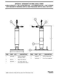
HYDRAULIC LINE CONNECTION DIAGRAM<br />
625 OR 625S SERIES LEVELING SYSTEMS<br />
(WITH 4 STRAIGHT-ACTING JACKS)<br />
NOTE: BEFORE OPERATING ANY MANUAL VALVE RELEASE<br />
READ AND UNDERSTAND PROCEDURE FOR MANUAL JACK<br />
RETRACTION IN OPERATOR’S INSTRUCTIONS. THIS MANIFOLD<br />
IS SHOWN WITH (1) LARGE VALVE WITH A VALVE RELEASE<br />
"T"-HANDLE, (2) SMALL VALVES WITH VALVE RELEASE NUTS<br />
AND (1) LARGE VALVE WITH A VALVE RELEASE NUT.<br />
BREATHER<br />
CAP<br />
LEFT<br />
FRONT<br />
SMALL VALVES<br />
WITH RELEASE<br />
NUTS<br />
LARGE VALVE<br />
WITH RELEASE<br />
"T" HANDLE<br />
NUT LOCATED<br />
WITH RELEASE<br />
LARGE VALVE<br />
UNDER<br />
PLASTIC PLUG<br />
RIGHT<br />
FRONT<br />
CHECK PUMP<br />
PRESSURE<br />
HERE<br />
LR<br />
LF<br />
RF<br />
RR<br />
SHUTTLE<br />
VALVE<br />
NOTE: SOME<br />
MANIFOLDS<br />
ARE EQUIPPED<br />
WITH VELOCITY<br />
VALVES<br />
50 PSI<br />
PRESSURE<br />
SWITCH<br />
NOTE: 50 PSI<br />
PRESSURE<br />
SWITCH MAY NOT<br />
BE USED ON ALL<br />
625 MANIFOLDS.<br />
3000 PSI<br />
PRESSURE<br />
SWITCH<br />
PUMP/MANIFOLD<br />
ASSEMBLY<br />
(ROOM EXTENSION MANIFOLD NOT SHOWN)<br />
MP65.2802<br />
LEFT<br />
REAR<br />
VELOCITY VALVE<br />
RIGHT<br />
REAR<br />
MP65.600C<br />
08SEP09
HYDRAULIC SCHEMATIC DIAGRAM<br />
BI-AXIS LEVELING WITH STRAIGHT-ACTING JACKS<br />
625 OR 625S SERIES<br />
M<br />
RELIEF VALVE<br />
3500 P.S.I.<br />
NOTE: 50 PSI PRESSURE SWITCH<br />
MAY NOT BE USED ON ALL 625 MANIFOLDS.<br />
RETURN<br />
PRESSURE<br />
HYDRAULIC<br />
POWER UNIT<br />
ROOM EXTENSION<br />
MANIFOLD LOCATED HERE<br />
WHEN APPLICABLE<br />
LEVELING SYSTEM<br />
SOLENOID MANIFOLD<br />
ASSEMBLY<br />
*3000 PSI<br />
SWITCH<br />
PRESSURE/RETURN<br />
SHUTTLE VALVE<br />
800 PSI TO SHIFT<br />
50 PSI<br />
SWITCH<br />
CHECK<br />
VALVE<br />
INNER<br />
SOL.VALVE<br />
LR<br />
SOL.VALVE<br />
LF<br />
SOL.VALVE<br />
RF<br />
SOL.VALVE<br />
RR<br />
CHECK<br />
VALVE<br />
OUTER<br />
LEFT<br />
FRONT<br />
RIGHT<br />
FRONT<br />
*JACK<br />
PRESSURE<br />
SWITCH<br />
LEFT REAR<br />
JACK<br />
CYLINDER<br />
* USED ON AUTOMATIC SYSTEMS ONLY<br />
RIGHT REAR<br />
MP65.601C<br />
08SEP09
HYDRAULIC LINE CONNECTION DIAGRAM<br />
MULTIPLE ROOM EXTENSIONS<br />
ROOM 1 (A)<br />
SEE HYDRAULIC LINE<br />
CONNECTION DIAGRAMS<br />
FOR ROOM EXTENSIONS<br />
FOR SPECIFIC CYLINDER<br />
CONNECTION DIAGRAMS<br />
RETRACT ROOM TO<br />
CHECK OIL LEVEL<br />
FRONT OF VEHICLE<br />
CAP END<br />
CONNECTION - A<br />
ROD END<br />
CONNECTION - B<br />
ROOM 3 (B)<br />
SEE HYDRAULIC LINE<br />
CONNECTION DIAGRAMS<br />
FOR ROOM EXTENSIONS<br />
FOR SPECIFIC CYLINDER<br />
CONNECTION DIAGRAMS<br />
EXTEND ROOM TO<br />
CHECK OIL LEVEL<br />
ROD END<br />
CONNECTION - B<br />
CAP END<br />
CONNECTION - A<br />
CAP POPPET<br />
SPRING O-RING<br />
CHECK<br />
VALVE<br />
ROOM 3 CYLINDER<br />
EXTEND VALVE<br />
ROOM 2 CYLINDER<br />
EXTEND VALVE<br />
VALVE RELEASE NUT<br />
ROOM 1 CYLINDER<br />
EXTEND VALVE<br />
ROOM 1 CYLINDER<br />
RETRACT VALVE<br />
VALVE RELEASE NUT<br />
ROOM 2 CYLINDER<br />
RETRACT VALVE<br />
ROOM 3 CYLINDER<br />
RETRACT VALVE<br />
ROOM 2 (A)<br />
SEE HYDRAULIC LINE<br />
CONNECTION DIAGRAMS<br />
FOR ROOM EXTENSIONS<br />
FOR SPECIFIC CYLINDER<br />
CONNECTION DIAGRAMS<br />
RETRACT ROOM TO<br />
CHECK OIL LEVEL<br />
MP65.3052<br />
CAP END<br />
CONNECTION - A<br />
ROD END<br />
CONNECTION - B<br />
NOTE: HYDRAULIC PUMP SHOWN WITH<br />
ROOM EXTENSION MANIFOLD ONLY.<br />
THE LEVELING SYSTEM MANIFOLD (NOT<br />
SHOWN) IS MOUNTED ON TOP OF THE<br />
ROOM EXTENSION MANIFOLD.<br />
MP65.6201<br />
27FEB06
CYLINDER CONNECTION DIAGRAM<br />
DUAL CYLINDER ROOM EXTENSIONS<br />
(WITH SYNCRONIZING CYLINDER)<br />
HIGH<br />
PRESSURE HOSE (B1)<br />
STEEL TUBE<br />
HYDRAULIC CYLINDER<br />
CAP END<br />
CONNECTION - A<br />
ROD END<br />
CONNECTION - B<br />
ROD END<br />
HIGH PRESSURE HOSE (B1)<br />
CAP END<br />
NOTE: THESE CONNECTIONS ARE<br />
(A1)<br />
THE SAME FOR EACH ROOM EXTENSION<br />
WITH DUAL ROOM CYLINDERS AND<br />
SYNCHRONIZING CYLINDER. NOT ALL<br />
ROOM EXTENSIONS WITH<br />
TEE<br />
DUAL CYLINDERS USE THE<br />
STEEL TUBE.<br />
(A1)<br />
SYNCHRONIZING CYLINDER<br />
CYLINDER EXTEND - ROOM EXTEND<br />
CYLINDER RETRACT - ROOM RETRACT<br />
CHECK OIL WITH ROOM RETRACTED<br />
STEEL TUBE<br />
HYDRAULIC CYLINDER<br />
ROD END<br />
CAP END<br />
DUAL CYLINDER ROOM EXTENSION<br />
VIEW 1<br />
IMPORTANT: THE LINES (A1) BETWEEN THE CAP END OF THE HYDRAULIC CYLINDERS AND THE TEE<br />
MUST BE THE SAME LENGTH AND DIAMETER.<br />
THE LINES (B1) BETWEEN THE ROD END OF THE HYDRAULIC CYLINDERS AND THE SYNCHRONIZING<br />
CYLINDER MUST BE THE SAME LENGTH AND DIAMETER. THE B1 LINES MUST BE HIGH PRESSURE HOSE.<br />
NOTE: DIFFERENT TYPES OF HOSE, ESPECIALLY HIGH PRESSURE HOSE, HAS BEEN USED. THE PRINTING ON A<br />
1/8" OR 3/16" HOSE BEING REPLACED MUST MATCH THE ORIGINAL HOSE. ALL <strong>HWH</strong> 1/4" HOSE IS THE SAME.<br />
VIEW 1<br />
* ROD END<br />
HIGH PRESSURE<br />
HOSE CONNECTION<br />
CAP END<br />
HOSE CONNECTION<br />
* IMPORTANT:<br />
HOSE CONNECTION AT REAR OF<br />
ROOM EXTENSION TUBE<br />
THE STEEL TUBE IS ALWAYS THE ROD END CONNECTION. SOMETIMES THE STEEL TUBE<br />
IS BELOW THE CAP END CONNECTION.<br />
MP65.3225<br />
MP65.7021<br />
20FEB06
HYDRAULIC LINE CONNECTION DIAGRAM<br />
SINGLE CYLINDER "GUIDED" ROOM EXTENSION<br />
NOTE: THE ROD END CONNECTION<br />
FROM THE MANIFOLD TO THE ROOM<br />
CYLINDER IS ALWAYS PRESSURIZED.<br />
CAP END<br />
CONNECTION - A<br />
ROD END<br />
CONNECTION - B<br />
CYLINDER RETRACT - ROOM RETRACT<br />
CYLINDER EXTEND - ROOM EXTEND<br />
CHECK OIL LEVEL WITH ROOM RETRACTED.<br />
MP65.930C<br />
17FEB06
HYDRAULIC LINE CONNECTION DIAGRAM<br />
LATERAL ARM ROOM EXTENSION<br />
(WITH SYNCHRONIZING CYLINDER)<br />
A HOSES MUST MAINTAIN EQUAL LENGTH<br />
AND DIAMETER.<br />
B HOSES MUST BE HIGH PRESSURE HOSES<br />
OF EQUAL LENGTH AND DIAMETER.<br />
A CAP END<br />
A CAP END<br />
B ROD END<br />
B ROD END<br />
SYNCHRONIZING CYLINDER<br />
ROD END CONNECTION - B<br />
CAP END CONNECTION - A<br />
CYLINDER EXTEND - ROOM RETRACT<br />
CYLINDER RETRACT - ROOM EXTEND<br />
CHECK OIL LEVEL WITH ROOM EXTENDED<br />
MP65.943D<br />
06AUG03
HYDRAULIC LINE CONNECTION DIAGRAM<br />
X-SLIDE ROOM EXTENSION<br />
(WITH SYNCHRONIZING CYLINDER)<br />
STEEL TUBE<br />
ROD END<br />
CONNECTION<br />
BOTTOM OF<br />
CYLINDER<br />
CAP END<br />
CONNECTION<br />
A CAP END<br />
A CAP END<br />
B ROD END<br />
B ROD END<br />
A HOSES MUST MAINTAIN EQUAL LENGTH<br />
AND DIAMETER.<br />
SYNCHRONIZING CYLINDER<br />
B HOSES MUST BE HIGH PRESSURE HOSES<br />
OF EQUAL LENGTH AND DIAMETER.<br />
CAP END CONNECTION - A<br />
ROD END CONNECTION - B<br />
CYLINDER EXTEND - ROOM RETRACT<br />
CYLINDER RETRACT - ROOM EXTEND<br />
CHECK OIL LEVEL WITH ROOM EXTENDED<br />
MP65.944D<br />
06AUG03
HYDRAULIC FLOW DIAGRAM<br />
VERTICAL ARM OR DUAL CYLINDER ROOM EXTENSION<br />
WITH SYNCHRONIZING CYLINDER<br />
STATIONARY POSITION<br />
FRONT CYLINDER<br />
FIXED TO<br />
VEHICLE<br />
SYNCHRONIZING<br />
VALVE<br />
SYNCHRONIZING<br />
VALVE<br />
SYNCHRONIZING CYLINDER<br />
FIXED TO<br />
VEHICLE<br />
REAR CYLINDER<br />
CYLINDER<br />
EXTEND<br />
VALVE<br />
CYLINDER<br />
RETRACT<br />
VALVE<br />
RETURN<br />
PRESSURE<br />
MP65.9455<br />
10NOV03
HYDRAULIC FLOW DIAGRAM<br />
SINGLE CYLINDER ROOM EXTENSION<br />
STATIONARY POSITION<br />
FIXED TO<br />
VEHICLE<br />
CYLINDER<br />
CYLINDER<br />
EXTEND<br />
VALVE<br />
CYLINDER<br />
RETRACT<br />
VALVE<br />
CHECK<br />
VALVE<br />
RETURN<br />
PRESSURE<br />
MP65.9459<br />
06NOV02
+<br />
_<br />
ELECTRICAL CONNECTION DIAGRAM<br />
625 SERIES LEVELING SYSTEM<br />
AIR DUMP - PARK BRAKE - MASTER WARNING LIGHT AND BUZZER<br />
TOUCH PANEL - JACK WARNING LIGHTS AND PRESSURE SWITCHES<br />
PRESSURE<br />
SWITCH<br />
TOUCH PANEL<br />
<strong>HWH</strong> COMPUTERIZED LEVELING<br />
PRESSURE<br />
SWITCH<br />
WARNING<br />
SWITCH<br />
HYD LEVEL<br />
STORE DUMP<br />
EXCESS<br />
SLOPE<br />
NOT IN<br />
PARK/<br />
BRAKE<br />
WARNING<br />
SWITCH<br />
LEFT FRONT<br />
MASTER<br />
WARNING<br />
LIGHT<br />
TRAVEL<br />
MODE<br />
OFF<br />
CAUTION!<br />
B A<br />
UNDERSTAND OPERATOR’S MANUAL BEFORE USING. BLOCK FRAME AND TIRES<br />
B A<br />
SECURELY BEFORE REMOVING TIRES OR CRAWLING UNDER VEHICLE.<br />
6235<br />
2000<br />
1000<br />
6235<br />
1200 2200<br />
FUSE<br />
5AMP<br />
6110<br />
BUZZER<br />
TO IGNITION<br />
TO ACCESSORY<br />
9300<br />
9301<br />
6230 - 6231<br />
RIGHT FRONT<br />
PILOT DUMP<br />
CONNECTION<br />
BY OEM<br />
DIODE<br />
6120<br />
SEE ELECTRICAL CONNECTION<br />
DIAGRAM - 625 SERIES<br />
LEVELING SYSTEM - LEVELING<br />
MANIFOLD - PUMP AND<br />
MASTER RELAYS<br />
6111 6111<br />
7699<br />
7699<br />
7699<br />
PARK BRAKE<br />
SWITCH<br />
DIODE<br />
6231<br />
6230<br />
TO <strong>HWH</strong><br />
GROUND<br />
STUD<br />
9000<br />
9001 - TO<br />
PARK BRAKE<br />
LIGHT<br />
C B A<br />
6231<br />
6230<br />
9300<br />
9301<br />
7699<br />
9000<br />
4 PIN<br />
GRAY<br />
12 PIN<br />
BROWN<br />
12 PIN<br />
GREEN<br />
12 PIN<br />
BLACK<br />
8 PIN<br />
BLACK<br />
12 PIN<br />
GRAY<br />
9301<br />
9300<br />
PILOT AIR DUMP<br />
CONNECTION<br />
PRESSURE<br />
SWITCH<br />
WARNING<br />
SWITCH<br />
PRESSURE<br />
SWITCH<br />
WARNING<br />
SWITCH<br />
LEFT REAR<br />
B A B A<br />
6235<br />
3000<br />
4000<br />
6235<br />
4200 3200<br />
RIGHT REAR<br />
MP85.102F<br />
16FEB05
ELECTRICAL CONNECTION DIAGRAM<br />
625 OR 625S SERIES LEVELING SYSTEMS<br />
LEVELING MANIFOLD<br />
PUMP AND MASTER RELAYS<br />
TO 50 LB PRESSURE SWITCH - 8101<br />
LEVELING MANIFOLD<br />
3400<br />
7601<br />
2400<br />
7600<br />
1400<br />
6240<br />
4400<br />
6240<br />
B A A B B A B A<br />
P.E.D P.E.D P.E.D P.E.D<br />
RR<br />
RF<br />
LF<br />
LR<br />
9300<br />
9301<br />
6230<br />
SEE ELECTRICAL<br />
CONNECTION<br />
DIAGRAM<br />
625 SERIES LEVELING<br />
SYSTEM - AIR DUMP<br />
TO <strong>HWH</strong><br />
GROUND STUD<br />
TO <strong>HWH</strong> GROUND STUD - 6240<br />
TO 3000 LB PRESSURE SWITCH - 8100<br />
12 PIN<br />
BROWN<br />
LEVELING<br />
MANIFOLD<br />
NOTE: ROOM EXTENSION<br />
MANIFOLD NOT SHOWN<br />
4 PIN<br />
GRAY<br />
12 PIN<br />
BLACK<br />
8 PIN<br />
BLACK<br />
12 PIN<br />
GRAY<br />
<strong>HWH</strong> GROUND<br />
STUD<br />
6231 - TO <strong>HWH</strong><br />
GROUND STUD<br />
6230 - TO <strong>HWH</strong><br />
GROUND STUD<br />
8600<br />
8500<br />
6800<br />
6100<br />
TO PUMP<br />
MOTOR<br />
TO +12V<br />
BATTERY<br />
PUMP<br />
RELAY<br />
MASTER<br />
RELAY<br />
MP85.102L<br />
09SEP09
ELECTRICAL CONNECTION DIAGRAM<br />
625 OR 625S SERIES LEVELING SYSTEMS<br />
CONTROL BOX - LED - FUSE LOCATION AND DESCRIPTION<br />
RIGHT<br />
REAR<br />
1<br />
2<br />
F1<br />
LED<br />
FUSE<br />
LEFT<br />
REAR<br />
SENSING UNIT<br />
+12V<br />
REAR<br />
RIGHT SIDE<br />
FRONT<br />
LEFT SIDE<br />
GROUND<br />
3<br />
4<br />
12<br />
11<br />
DUMP<br />
F2<br />
F6<br />
CRX2<br />
19<br />
14<br />
13<br />
MASTER<br />
RELAY<br />
RIGHT<br />
FRONT<br />
F7<br />
OLD<br />
BOARD<br />
LOCATION<br />
NOTE: FOR DETAILED INPUT / OUTPUT INFORMATION ABOUT<br />
PIN CONNECTIONS SEE ELECTRICAL CONNECTION<br />
DIAGRAM - CONTROL BOX CONNECTION INFORMATION.<br />
NOTE: A LIT YELLOW LED INDICATES THERE IS A GROUND<br />
SIGNAL TO TURN THE CORRESPONDING RELAY ON.<br />
A LIT RED LED INDICATES THERE IS<br />
VOLTAGE ON IT’S CORRESPONDING OUTPUT PIN.<br />
IF A YELLOW LED IS LIT AND THE<br />
CORRESPONDING RED LED IS OFF, EITHER<br />
IT’S FUSE IS BLOWN OR THE RELAY IS BAD.<br />
5<br />
6<br />
16<br />
15<br />
PUMP<br />
RELAY<br />
21<br />
22<br />
23<br />
24<br />
25<br />
26<br />
27<br />
28<br />
IF THE YELLOW LED’S ARE WORKING BUT NO RED LED<br />
IS COMING ON THERE MAY BE PROBLEM WITH INPUT<br />
VOLTAGE IN THE 4-PIN CONNECTOR.<br />
F3<br />
F8<br />
LEFT<br />
FRONT<br />
7<br />
8<br />
18<br />
17<br />
TRAVEL<br />
29 30 31<br />
(39)<br />
F4<br />
F9<br />
20<br />
CRX1<br />
32 33 34 35<br />
9 36 37 38<br />
F12<br />
F10<br />
PF3<br />
36 37 38<br />
PF4 (F11)<br />
LED<br />
1-YELLOW<br />
2-RED<br />
3-YELLOW<br />
4-RED<br />
5-YELLOW<br />
6-RED<br />
7-YELLOW<br />
8-RED<br />
11-YELLOW<br />
12-RED<br />
13-YELLOW<br />
14-RED<br />
15-YELLOW<br />
16-RED<br />
17-YELLOW<br />
18-RED<br />
19-YELLOW<br />
20-YELLOW<br />
21-YELLOW<br />
22-YELLOW<br />
23-YELLOW<br />
24-YELLOW<br />
25-RED<br />
26-RED<br />
27-RED<br />
28-RED<br />
29-RED<br />
30-YELLOW<br />
31-GREEN<br />
32-RED<br />
33-GREEN<br />
34-RED<br />
35-RED<br />
36-RED<br />
37-RED<br />
38-RED<br />
(39) 9-RED<br />
RELAY DESCRIPTION<br />
RIGHT REAR COIL<br />
RIGHT REAR OUTPUT<br />
LEFT REAR COIL<br />
LEFT REAR OUTPUT<br />
RIGHT FRONT COIL<br />
RIGHT FRONT OUTPUT<br />
LEFT FRONT COIL<br />
LEFT FRONT OUTPUT<br />
DUMP COIL<br />
DUMP OUTPUT<br />
MASTER RELAY COIL<br />
MASTER RELAY OUTPUT<br />
PUMP COIL<br />
PUMP OUTPUT<br />
TRAVEL COIL<br />
TRAVEL OUTPUT<br />
CRX 2<br />
CRX 1<br />
LEFT FRONT WARN SW<br />
RIGHT FRONT WARN SW<br />
RIGHT REAR WARN SW<br />
LEFT REAR WARN SW<br />
LEFT FRONT PRESS SW<br />
RIGHT FRONT PRESS SW<br />
RIGHT REAR PRESS SW<br />
LEFT REAR PRESS SW<br />
NOT USED<br />
NOT USED<br />
3000 LB PRESS SW INPUT<br />
MASTER WARN CONTROL<br />
50 LB PRESS SW INPUT<br />
JACK INTERRUPT<br />
PARK BRAKE<br />
BOARD ENABLE<br />
ACCESSORY IN<br />
ACCESSORY OUT FOR<br />
MASTER WARNING<br />
LINK LIGHT<br />
FUSE<br />
F1 - 15 AMP<br />
F2 - 15 AMP<br />
F3 - 15 AMP<br />
F4 - 15 AMP<br />
F6 - 5 AMP<br />
F7 - 5 AMP<br />
F8 - 5 AMP<br />
F9 - 5 AMP<br />
F10 - 10 AMP<br />
PF4 (F11)<br />
NOTE: THE TRAVEL RELAY IS WIRED AS A<br />
NORMALLY CLOSED RELAY. WHEN THE YELLOW<br />
LED (17) IS ON THE RELAY CONTACTS WILL OPEN.<br />
THE RED LED (18) WILL NOT BE ON. THE RED LED<br />
WILL BE ON IF THE LEVELING SYSTEM IS IN THE<br />
TRAVEL MODE AND THE IGNITION IS ON.<br />
NOTE: THE TRAVEL RELAY IS NOT USED ON<br />
VEHICLES EQUIPPED WITH <strong>HWH</strong> AIR DUMP SYSTEMS.<br />
IT IS ONLY USED WITH PILOT OPERATED AIR DUMP<br />
SYSTEMS.<br />
IF A YELLOW LED IS NOT LIT, THERE IS A PROBLEM WITH<br />
THE CONTROL BOX, TOUCH PANEL OR CONNECTION CABLE.<br />
LED’S 19 AND 20 (YELLOW) WILL BE ON WHENEVER THE<br />
TOUCH PANEL IS ON UNLESS THE "STORE" BUTTON IS<br />
PUSHED. TWO SECONDS AFTER THE "STORE" BUTTON<br />
IS PUSHED, LED’s 7 AND 20 WILL TURN OFF. 5 SECONDS<br />
LATER LED’S 3 AND 19 WILL TURN OFF.<br />
MP85.184J<br />
NOTE: ON NEWER CONTROL BOXES, FUSE F11 AND FUSE<br />
F12 HAVE BEEN REPLACED WITH POLY SWITCHES PF4<br />
AND PF3. POLY SWITCHES PROTECT A COMPONENT OR<br />
WIRE AS A FUSE DOES EXCEPT THE POLY SWITCH WILL<br />
ALLOW CURRENT THROUGH WHEN THE OVERLOAD OR<br />
SHORT IS REMOVED. POLY SWITCHES ARE NOT<br />
REPLACEABLE.<br />
MP85.184C<br />
08SEP09
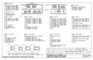
ELECTRICAL CONNECTION DIAGRAM<br />
625 SERIES LEVELING SYSTEM<br />
TOUCH PANEL CONNECTIONS<br />
<strong>HWH</strong> COMPUTERIZED LEVELING<br />
HYD<br />
LEVEL<br />
EXCESS<br />
SLOPE<br />
STORE<br />
DUMP<br />
NOT IN<br />
PARK/<br />
BRAKE<br />
OFF<br />
TRAVEL<br />
MODE<br />
CAUTION!<br />
UNDERSTAND OPERATOR’S MANUAL BEFORE USING. BLOCK FRAME AND TIRES<br />
SECURELY BEFORE REMOVING TIRES OR CRAWLING UNDER VEHICLE.<br />
PIN 1<br />
LINK LIGHT<br />
PIN #<br />
WIRE<br />
COLOR<br />
WIRE<br />
NUMBER<br />
WIRE DESCRIPTION AND FUNCTION<br />
1<br />
2<br />
3<br />
4<br />
5<br />
YELLOW<br />
GREEN<br />
WHITE<br />
RED<br />
6230<br />
6800<br />
CAN HIGH<br />
CAN LOW<br />
CAN SHEILD<br />
GROUND FROM CONTROL BOX<br />
SWITCHED BATTERY FROM CONTROL BOX<br />
MP85.185E<br />
MP85.2915<br />
13MAY04
ELECTRICAL CONNECTION DIAGRAM<br />
625 OR 625S SERIES LEVELING SYSTEMS<br />
CONTROL BOX CONNECTION INFORMATION<br />
PIN 1<br />
PIN 12<br />
PIN 1<br />
PIN 4<br />
PIN 1<br />
PIN 8<br />
4 PIN<br />
GRAY<br />
CN3<br />
12 PIN<br />
BROWN<br />
CN7<br />
12 PIN<br />
BLACK<br />
CN8<br />
8 PIN<br />
BLACK<br />
PIN 12<br />
PIN 1<br />
PIN 1<br />
CN6<br />
12 PIN<br />
GRAY<br />
PIN 12<br />
PIN #<br />
WIRE<br />
COLOR<br />
WIRE<br />
NUMBER<br />
WIRE DESCRIPTION AND FUNCTION<br />
4 PIN GRAY CONNECTOR<br />
1<br />
BLACK<br />
6800 SWITCHED +12V BATTERY POWER FROM MASTER RELAY<br />
2<br />
BLACK<br />
6800 SWITCHED +12V BATTERY POWER FROM MASTER RELAY<br />
3<br />
WHITE<br />
6230 GROUND FROM <strong>HWH</strong> GROUND STUD<br />
4<br />
RED<br />
6100 +12 BATTERY FROM MASTER RELAY<br />
12 PIN BROWN CONNECTOR - CN3<br />
1<br />
BLACK 8500 MASTER RELAY CONTROL - SWITCHED +12<br />
2<br />
BLACK<br />
8100 3000 LB PRESSURE SWITCH - SWITCHED GROUND<br />
3<br />
BLACK<br />
8101 50 LB PRESSURE SWITCH - SWITCHED GROUND<br />
4<br />
BLACK 9301 SWITCHED +12 FOR TRAVEL<br />
5<br />
BLACK<br />
1400 SWITCHED +12 FOR LEFT FRONT SOLENOID VALVE<br />
6 BLACK<br />
7600 GROUND FOR RIGHT FRONT SOLENOID VALVE<br />
7<br />
BLACK<br />
7601 GROUND FOR RIGHT REAR SOLENOID VALVE<br />
8<br />
BLACK 4400 SWITCHED +12 FOR LEFT REAR SOLENOID VALVE<br />
9<br />
BLACK<br />
3400 SWITCHED +12 FOR RIGHT REAR SOLENOID VALVE<br />
10 BLACK<br />
2400 SWITCHED +12 FOR RIGHT FRONT SOLENOID VALVE<br />
11 BLACK 9300 SWITCHED +12 FOR DUMP<br />
12 BLACK<br />
8600 PUMP RELAY CONTROL - SWITCHED +12<br />
12 PIN BLACK CONNECTOR - CN7<br />
1 THRU 6<br />
NO CONNECTION<br />
7 BLACK 9000 SWITCHED GROUND FROM PARK BRAKE SWITCH<br />
8 THRU 10<br />
NO CONNECTION<br />
11 BLACK<br />
7699 BUZZER & MASTER WARNING LIGHT CONTROL - SWITCHED GROUND<br />
12<br />
NO CONNECTION<br />
8 PIN BLACK CONNECTOR - CN8<br />
1 AND 2<br />
NO CONNECTION<br />
3<br />
RED<br />
6800 SWITCHED BATTERY<br />
4<br />
WHITE<br />
6230 GROUND<br />
5<br />
CAN SHIELD<br />
6 RED 6120 +12 ACCESSORY / IGNITION<br />
7<br />
GREEN<br />
CAN LOW<br />
8 YELLOW<br />
CAN HIGH<br />
12 PIN GRAY CONNECTOR - CN6<br />
1 AND 2<br />
NO CONNECTION<br />
3<br />
BLACK<br />
1000 SWITCHED GROUND FROM LEFT FRONT WARNING SWITCH<br />
4<br />
BLACK<br />
2000 SWITCHED GROUND FROM RIGHT FRONT WARNING SWITCH<br />
5<br />
BLACK 1200 SWITCHED GROUND FROM LEFT FRONT PRESSURE SWITCH<br />
6<br />
BLACK 2200 SWITCHED GROUND FROM RIGHT FRONT PRESSURE SWITCH<br />
7<br />
BLACK 3200 SWITCHED GROUND FROM RIGHT REAR PRESSURE SWITCH<br />
8<br />
BLACK 4200 SWITCHED GROUND FROM LEFT REAR PRESSURE SWITCH<br />
9<br />
BLACK 3000 SWITCHED GROUND FROM RIGHT REAR WARNING SWITCH<br />
10 BLACK 4000 SWITCHED GROUND FROM LEFT REAR WARNING SWITCH<br />
11<br />
NO CONNECTION<br />
12 WHITE<br />
6235 SHARED GROUND FOR WARNING SWITCHES<br />
MP85.186E<br />
MP85.6031<br />
09SEP09
ELECTRICAL CONNECTION DIAGRAM<br />
MULTIPLE ROOM EXTENSIONS<br />
TOP VIEW<br />
1E<br />
1R<br />
2E<br />
2R<br />
3E<br />
3R<br />
P.E.D<br />
P.E.D<br />
P.E.D<br />
P.E.D<br />
P.E.D<br />
P.E.D<br />
B<br />
A<br />
B<br />
A<br />
TO <strong>HWH</strong> GROUND<br />
6245 6246<br />
STUD ON PUMP<br />
B A B B<br />
A A B A<br />
5052<br />
5051<br />
5050<br />
5152<br />
5151<br />
5150<br />
6810<br />
12 PIN<br />
BROWN<br />
1E - ROOM 1 CYL EXTEND - ROOM EXTEND<br />
1R - ROOM 1 CYL RETRACT - ROOM RETRACT<br />
2E - ROOM 2 CYL EXTEND - ROOM EXTEND<br />
2R - ROOM 2 CYL RETRACT - ROOM RETRACT<br />
3E - ROOM 3 CYL EXTEND - ROOM RETRACT<br />
3R - ROOM 3 CYL RETRACT - ROOM EXTEND<br />
12 PIN<br />
GREEN<br />
4 PIN<br />
GRAY<br />
12 PIN<br />
BLACK<br />
8 PIN<br />
BLACK<br />
12 PIN<br />
GRAY<br />
NOTE: LEVELING SYSTEM<br />
MANIFOLD NOT SHOWN.<br />
ROOM EXTENSION<br />
MANIFOLD<br />
CYLINDER EXTEND<br />
VALVE<br />
CYLINDER<br />
RETRACT<br />
VALVE<br />
6810<br />
PUMP<br />
RELAY<br />
<strong>HWH</strong> GROUND<br />
STUD<br />
MASTER<br />
RELAY<br />
MP85.6100<br />
02OCT03
ELECTRICAL CONNECTION DIAGRAM<br />
MULTIPLE ROOM EXTENSIONS<br />
ROOM CONTROL CONNECTIONS<br />
PIN 13<br />
PIN 10<br />
PIN 7<br />
PIN 4<br />
PIN 1<br />
PIN 14<br />
PIN 11<br />
PIN 8<br />
PIN 5<br />
PIN 2<br />
ROOM CONTROL SWITCHES<br />
AND CONNECTIONS ARE<br />
SUPPLIED BY 0.E.M.<br />
PIN 15<br />
PIN 12<br />
PIN 9<br />
PIN 6<br />
PIN 3<br />
PIN 1 - <strong>HWH</strong> (BLACK 5000) - ROOM 1 EXTEND<br />
WINNEBAGO (DR)<br />
PIN 2 - <strong>HWH</strong> (BLACK 5100) - ROOM 1 RETRACT<br />
WINNEBAGO (DU)<br />
PIN 3 - <strong>HWH</strong> (BLACK 6810) - ROOM 1 SWITCHED BATTERY<br />
WINNEBAGO (CCZ)<br />
PIN 4 - <strong>HWH</strong> (BLACK 5001) - ROOM 2 EXTEND<br />
WINNEBAGO (BBM)<br />
PIN 5 - <strong>HWH</strong> (BLACK 5101) - ROOM 2 RETRACT<br />
WINNEBAGO (BBN)<br />
PIN 6 - <strong>HWH</strong> (BLACK 6811) - ROOM 2 SWITCHED BATTERY<br />
WINNEBAGO (KKK)<br />
PIN 7 - <strong>HWH</strong> (BLACK 5002) - ROOM 3 EXTEND<br />
WINNEBAGO (HHE)<br />
PIN 8 - <strong>HWH</strong> (BLACK 5102) - ROOM 3 RETRACT<br />
WINNEBAGO (HHF)<br />
PIN 9 - <strong>HWH</strong> (BLACK 6812) - ROOM 3 SWITCHED BATTERY<br />
WINNEBAGO (KKL)<br />
PIN 10 THRU 12 - NO CONNECTION<br />
PIN 13 - <strong>HWH</strong> (BLACK 8601) - PUMP RELAY CONTROL<br />
WINNEBAGO (DDA)<br />
PIN 14 - <strong>HWH</strong> (RED 6100) - BATTERY<br />
WINNEBAGO (CCY)<br />
PIN 15 - NO CONNECTION<br />
12 PIN<br />
BLACK<br />
CONNECTOR<br />
6100<br />
8601<br />
12 PIN<br />
BLACK<br />
CONNECTOR<br />
NOTE: THE BOX CONNECTORS ARE<br />
KEYED TO PREVENT PLUGGING THE<br />
CONNECTORS IN THE WRONG POSITION.<br />
LEVEL SENSOR<br />
ADJUSTMENT<br />
MP85.6121<br />
07OCT05
ELECTRICAL CONNECTION DIAGRAM<br />
MULTIPLE ROOM EXTENSIONS<br />
CONTROL BOX CONNECTION INFORMATION - (PAGE 1 OF 2)<br />
12 PIN<br />
PIN 1<br />
PIN 12<br />
GREEN<br />
PIN #<br />
WIRE<br />
COLOR<br />
WIRE<br />
NUMBER<br />
WIRE DESCRIPTION AND FUNCTION<br />
GREEN CONNECTOR<br />
12 PIN GREEN CONNECTOR<br />
1<br />
BLACK<br />
5050 SWITCHED +12 FOR ROOM 1 CYL EXT SOLENOID VALVE<br />
2<br />
BLACK<br />
5150 SWITCHED +12 FOR ROOM 1 CYL RET SOLENOID VALVE<br />
3<br />
BLACK<br />
5051 SWITCHED +12 FOR ROOM 2 CYL EXT SOLENOID VALVE<br />
4<br />
BLACK<br />
5151 SWITCHED +12 FOR ROOM 2 CYL RET SOLENOID VALVE<br />
5<br />
BLACK<br />
5152 SWITCHED +12 FOR ROOM 3 CYL RET SOLENOID VALVE<br />
6<br />
BLACK<br />
5052 SWITCHED +12 FOR ROOM 3 CYL EXT SOLENOID VALVE<br />
7 & 8 NO CONNECTION<br />
9<br />
BLACK<br />
6810 +12 BATTERY FROM MASTER RELAY<br />
10 BLACK<br />
6810 +12 BATTERY FROM MASTER RELAY<br />
11 BLACK<br />
6810 +12 BATTERY FROM MASTER RELAY<br />
12 BLACK<br />
6810 +12 BATTERY FROM MASTER RELAY<br />
MP85.6136<br />
29APR04
ELECTRICAL CONNECTION DIAGRAM<br />
MULTIPLE ROOM EXTENSIONS<br />
CONTROL BOX CONNECTION INFORMATION - (PAGE 2 OF 2)<br />
12 PIN<br />
BLACK<br />
CN2<br />
PIN 1 PIN 12<br />
12 PIN<br />
BLACK<br />
CN1<br />
PIN 1<br />
PIN 12<br />
LEVEL SENSOR<br />
ADJUSTMENT<br />
PIN #<br />
WIRE<br />
COLOR<br />
WIRE<br />
NUMBER<br />
WIRE DESCRIPTION AND FUNCTION<br />
CN2 - 12 PIN BLACK CONNECTOR (SIDE MOUNTED)<br />
1<br />
2<br />
3<br />
BLACK<br />
BLACK<br />
BLACK<br />
6810<br />
5000<br />
5100<br />
4<br />
5<br />
BLACK<br />
BLACK<br />
6811<br />
5001<br />
6<br />
BLACK<br />
5101<br />
7 & 8<br />
9<br />
10<br />
11<br />
BLACK<br />
8601<br />
RED<br />
6100<br />
12<br />
NO CONNECTION<br />
CN1 - 12 PIN BLACK CONNECTOR (SIDE MOUNTED)<br />
1<br />
BLACK 6812<br />
2<br />
3<br />
4 THRU 9<br />
BLACK<br />
BLACK<br />
5002<br />
5102<br />
10<br />
11<br />
12<br />
BLACK<br />
RED<br />
8601<br />
6100<br />
SWITCHED +12 BATT FROM PUMP RELAY - ROOM 1<br />
SWITCHED +12 FOR ROOM EXT FROM CONTROL PANEL - ROOM 1<br />
SWITCHED +12 FOR ROOM RET FROM CONTROL PANEL - ROOM 1<br />
SWITCHED +12 BATT FROM PUMP RELAY - ROOM 2<br />
SWITCHED +12 FOR ROOM EXT FROM CONTROL PANEL - ROOM 2<br />
SWITCHED +12 FOR ROOM RET FROM CONTROL PANEL - ROOM 2<br />
NO CONNECTION<br />
KEY PIN (NO CONNECTION)<br />
SWITCHED +12 FOR PUMP RELAY FROM CONTROL PANEL<br />
+12 BATTERY FROM MASTER RELAY<br />
SWITCHED +12 BATT FROM PUMP RELAY - ROOM 3<br />
SWITCHED +12 FOR ROOM EXT FROM CONTROL PANEL - ROOM 3<br />
SWITCHED +12 FOR ROOM RET FROM CONTROL PANEL - ROOM 3<br />
NO CONNECTION<br />
SWITCHED +12 FOR PUMP RELAY FROM CONTROL PANEL<br />
+12 BATTERY FROM MASTER RELAY<br />
NO CONNECTION (KEY PIN)<br />
MP85.6141<br />
06NOV03
BREATHER CAP - DIPSTICK - 1/4" NUT DRIVER<br />
VALVE RELEASE<br />
NUT<br />
NOTE: DO NOT turn the valve<br />
release nut more than 4 and 1/2<br />
(four and one half) turns counter<br />
clockwise. Damage to the valve<br />
may result.<br />
1 1/2" DIAMETER<br />
SOLENOID VALVE<br />
PLASTIC PLUG<br />
REMOVE TO<br />
GAIN ACCESS<br />
TO THE 1/4"<br />
VALVE RELEASE<br />
NUT<br />
VALVE RELEASE<br />
NUT<br />
NOTE: DO NOT turn the valve<br />
release nut more than 2 full<br />
turns counter clockwise. Damage<br />
to the valve may result.<br />
2 1/4" DIAMETER<br />
SOLENOID VALVE<br />
NOTE: THE BREATHER CAP IS LOCATED<br />
ON THE TOP SIDE OF THE POWER UNIT RESERVOIR.<br />
1/4" NUT DRIVER<br />
OIL LEVEL<br />
OIL LEVEL GROOVES<br />
BREATHER CAP<br />
IMPORTANT: PRIOR TO REMOVING THE BREATHER CAP,<br />
EITHER TO CHECK THE OIL LEVEL OR TO USE THE 1/4" NUT DRIVER,<br />
CLEAN ANY DEBRIS FROM THE TOP OF THE RESERVOIR.<br />
BEFORE RETURNING THE BREATHER CAP TO THE RESERVOIR,<br />
REMOVE ANY PAINT CHIPS OR OTHER DEBRIS FROM THE DIPSTICK<br />
INCLUDING DEBRIS INSIDE THE 1/4" NUT DRIVER.<br />
MP85.999X<br />
20JAN10