Indoor Installation MPCW Series 7 Wireless Receiver (Top ... - Nevco
Indoor Installation MPCW Series 7 Wireless Receiver (Top ... - Nevco
Indoor Installation MPCW Series 7 Wireless Receiver (Top ... - Nevco

Create successful ePaper yourself
Turn your PDF publications into a flip-book with our unique Google optimized e-Paper software.
4<br />
3<br />
2<br />
1<br />
Rev<br />
B<br />
D<br />
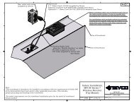
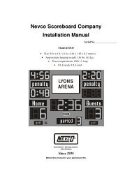
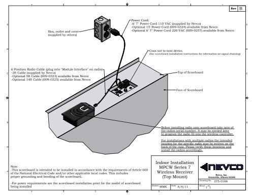
Box, outlet and cover<br />
(supplied by others)<br />
Power Cord:<br />
-6' 7" Power Cord 110 VAC (supplied by <strong>Nevco</strong>)<br />
-Optional 15' Power Cord (009-0324) available from <strong>Nevco</strong><br />
-Optional 6' 7" Power Cord 220 VAC (009-0257) available from <strong>Nevco</strong><br />
D<br />
Coax out to next device.<br />
(See scoreboard installation instructions for information on signal chaining)<br />
C<br />
6 Position Radio Cable (plug into "Module Interface" on radio)<br />
-2ft Cable (supplied by <strong>Nevco</strong>)<br />
-Optional 5ft Cable (009-0323) available from <strong>Nevco</strong><br />
-Optional 14ft Cable (009-0325) available from <strong>Nevco</strong><br />
<strong>Top</strong> of Scoreboard<br />
C<br />
Face of Scoreboard<br />
B<br />
B<br />
Before installing radio onto scoreboard take note of<br />
the radios serial number. It may be needed later<br />
to program the radio ID into the wireless controller.<br />
For installations with multiple radios the intended<br />
location for the specific radio may be written on the<br />
back of the case. Please verify these locations and<br />
install the radios accordingly.<br />
A<br />
Note:<br />
-This scoreboard is intended to be installed in accordance with the requirements of Article 600<br />
of the National Electrical Code and/or other applicable local codes. This includes<br />
proper grounding and bonding of the scoreboard.<br />
-For power requirements see the scoreboard installation print for the model of scoreboard<br />
being installed<br />
Drawn<br />
<strong>Indoor</strong> <strong>Installation</strong><br />
<strong>MPCW</strong> <strong>Series</strong> 7<br />
<strong>Wireless</strong> <strong>Receiver</strong><br />
(<strong>Top</strong> Mount)<br />
Date<br />
MMK 8/8/11<br />
Drawing No.<br />
Sheet of<br />
<strong>Nevco</strong>, Inc.<br />
Greenville, Illinois 62246<br />
1 1<br />
275-0166<br />
A<br />
4<br />
3<br />
2<br />
1
D<br />
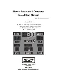
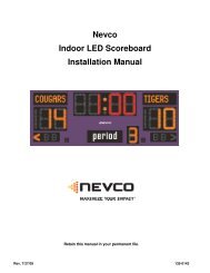
Display Connections<br />
4<br />
3<br />
Box outlet and cover:<br />
- Supplies power to scoreboard,<br />
message center and POE.<br />
- (supplied by others)<br />
- Power cords for scoreboard and POE<br />
are supplied by <strong>Nevco</strong>.<br />
2<br />
<strong>Wireless</strong> <strong>Receiver</strong><br />
(scoreboard)<br />
1<br />
Rev<br />
A<br />
Phone Cable 2' long from<br />
receiver to scoreboard.<br />
(supplied by <strong>Nevco</strong>)<br />
D<br />
Client Bridge<br />
- for lower message center<br />
- see sheet 3 for mounting<br />
C<br />
A<br />
Ethernet from Client<br />
Bridge to POE "POE"<br />
(25').<br />
C<br />
Ethernet Crossover<br />
from LAN-IN on POE<br />
to message center<br />
Signal-In (25')<br />
Power Over Ethernet<br />
Supply (see detail<br />
view of on sheet 2)<br />
DETAIL A<br />
Notes:<br />
1. Remove nearby access panel to<br />
make signal connection (signal<br />
connection located insided cabinet)<br />
B<br />
Carefully Remove knockout<br />
in panel to make connection.<br />
2. Panel may be placed on bottom<br />
of message center on this side. See<br />
detail to right.<br />
B<br />
B<br />
Ethernet crossover<br />
to message center<br />
Signal-In<br />
Feed panel through hole<br />
as shown to change<br />
location of power/signalin<br />
panel.<br />
A<br />
4<br />
3<br />
DETAIL B<br />
Drawn<br />
Hybrid 16mm/20mm<br />
<strong>Wireless</strong> <strong>Indoor</strong> Signal<br />
Connections<br />
2<br />
Date<br />
DBB 04/07/10<br />
Drawing No.<br />
Sheet of<br />
<strong>Nevco</strong>, Inc.<br />
Greenville, Illinois 62246<br />
1 3<br />
275-0576<br />
1<br />
A
D<br />
4<br />
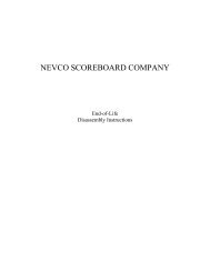
Control Room Connections<br />
D<br />
3<br />
Client Bridge<br />
2<br />
Access<br />
Point<br />
1<br />
Rev<br />
A<br />
Remove cover and<br />
plug into ethernet<br />
port closest to the<br />
center of the access<br />
point.<br />
D<br />
Client Bridge<br />
Signal strength meter<br />
should have 3 bars lighted<br />
for adequate signal<br />
See important note below<br />
Access Point<br />
C<br />
C<br />
3' crossover from<br />
POE to PC.<br />
3' Crossover Cable<br />
(color coded red)<br />
"POE"<br />
Straight<br />
Through Cable<br />
(color coded<br />
white)<br />
"LAN"<br />
B<br />
A<br />
4<br />
Power cord for POE<br />
(supplied by <strong>Nevco</strong>)<br />
Important<br />
<strong>Wireless</strong> devices should be in Clear Line of Sight from each other. Penetration of<br />
obstacles by the wireless signal is dependant on the material of the obstacle as well<br />
as the overall distance between devices.<br />
3<br />
Note: Refer to drawing<br />
276-0671 for scoreboard<br />
and VSBI connection<br />
instructions.<br />
Drawn<br />
Hybrid 16mm/20mm<br />
<strong>Wireless</strong> <strong>Indoor</strong> Signal<br />
Connections<br />
2<br />
Date<br />
Power Over<br />
Ethernet<br />
Supply<br />
Drawing No.<br />
Sheet of<br />
DBB 04/07/10 2 3<br />
<strong>Nevco</strong>, Inc.<br />
Greenville, Illinois 62246<br />
275-0576<br />
1<br />
B<br />
A
4<br />
3<br />
2<br />
1<br />
Rev<br />
A<br />
D<br />
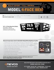
Fasten client bridge to<br />
mounting bracket using<br />
2 supplied zip-ties.<br />
D<br />
Bolt or clamp bracket to<br />
column or other structure.<br />
(hardware supplied by others)<br />
C<br />
C<br />
Run zip-ties through two<br />
holes in bracket and through<br />
slot on client bridge.<br />
B<br />
B<br />
Client bridge can be mounted<br />
to bracket at various angles to<br />
achieve optimum line of sight<br />
to access point in control room.<br />
A<br />
4<br />
3<br />
Drawn<br />
Hybrid 16mm/20mm<br />
<strong>Wireless</strong> <strong>Indoor</strong> Signal<br />
Connections<br />
2<br />
Date<br />
Drawing No.<br />
Sheet of<br />
DBB 04/07/10 3 3<br />
<strong>Nevco</strong>, Inc.<br />
Greenville, Illinois 62246<br />
275-0576<br />
1<br />
A