

An Introduction to the Ericsson Transport Network Architecture ...
An Introduction to the Ericsson Transport Network Architecture ...
An Introduction to the Ericsson Transport Network Architecture ...

Create successful ePaper yourself
Turn your PDF publications into a flip-book with our unique Google optimized e-Paper software.
76<br />
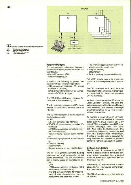
Fig 10<br />
SMUX Control System Hardware implementation<br />
TAU<br />
MAU<br />
AUI<br />
LAN<br />
Termination Access Unit<br />
Medium Attachment Unit<br />
Attachment Unit Interface<br />
Local Area <strong>Network</strong><br />
Hardware Platform<br />
The management subsystem hardware<br />
platform consists of processors at two different<br />
levels:<br />
- Central Processor (SU)<br />
- Unit Processors (UP).<br />
In addition, <strong>the</strong> following equipment may<br />
be required for control and operation:<br />
- IBM-compatible 386/486 PC (Local<br />
Opera<strong>to</strong>r's Terminal)<br />
- MAU (E<strong>the</strong>rnet transceiver) for connection<br />
<strong>to</strong> a DCN of LAN type.<br />
The SMUX Control System Hardware <strong>Architecture</strong><br />
is illustrated in Fig. 10.<br />
The SU communicates with <strong>the</strong> UPs via an<br />
internal ISO 8482 bus, which is similar <strong>to</strong><br />
RS-485.<br />
The SU implementation is mainly based on<br />
<strong>the</strong> following circuits:<br />
-CPU<br />
- E<strong>the</strong>rnet controller (Q3-interface)<br />
- RS-232 Communication controller (Finterface)<br />
- LAPD Communication controllers (internal<br />
communication)<br />
- Relay contacts (Station alarm interfaces)<br />
- Detection logic (External alarm interfaces)<br />
- Program memory<br />
- Data memory<br />
- Backup memory for non-volatile data.<br />
The UP is a general hardware building<br />
block common <strong>to</strong> all transmission printed<br />
board assemblies. The UP implementation<br />
is mainly based on <strong>the</strong> following circuits:<br />
-CPU<br />
- LAPD communication controllers (ECC<br />
and internal communication)<br />
- A/D and D/A converters, for measurement<br />
of laser characteristics, such as<br />
input power and laser bias current<br />
- Test interface (gains access <strong>to</strong> UP software<br />
for an authorised user)<br />
- Program memory<br />
- Data memory<br />
- Backup memory for non-volatile data.<br />
Not all UP circuits have <strong>to</strong> be present on<br />
every transmission printed board assembly.<br />
The CPU used both for SU and UPs is <strong>the</strong><br />
Mo<strong>to</strong>rola 68 302, which is a microprocessor<br />
optimised for data communication<br />
(ISDN) purposes.<br />
<strong>An</strong> IBM-compatible 386/486 PC is used as<br />
Local Opera<strong>to</strong>r Terminal. The LOT provides<br />
<strong>the</strong> opera<strong>to</strong>r with a <strong>Network</strong> Element<br />
view. However, it is possible <strong>to</strong> manage<br />
small networks from <strong>the</strong> LOT, but of course<br />
without network view.<br />
To manage a network from an LOT without<br />
assistance from <strong>the</strong> FMAS, communication<br />
over <strong>the</strong> ECCs is used, Box 2. By<br />
using ECC it is possible for an LOT <strong>to</strong> exchange<br />
messages with any o<strong>the</strong>r<br />
SDH NEs within <strong>the</strong> SDH network. This<br />
possibility (of accessing remotely located<br />
SDH NEs) is referred <strong>to</strong> as Remote Login.<br />
It will be a valuable feature, especially for<br />
early field trials and installations without a<br />
complete <strong>Network</strong> Management System.<br />
Software <strong>Architecture</strong><br />
The SU and UP software in an SMUX<br />
forms a loosely coupled, distributed software<br />
system organised in<strong>to</strong> a layered<br />
structure, where each layer has a well defined<br />
task, Fig. 11.<br />
Additionally, PC software which is not indicated<br />
in Fig. 11 is required for <strong>the</strong> Graphical<br />
User Interface.<br />
The SU software layers and <strong>the</strong>ir tasks are<br />
as follows:<br />
ERICSSON REVIEW No. 3, 1992


