

1 - ericssonhistory.com
1 - ericssonhistory.com
1 - ericssonhistory.com

You also want an ePaper? Increase the reach of your titles
YUMPU automatically turns print PDFs into web optimized ePapers that Google loves.
•<br />
The four-wire circuit permits a long speaker circuit connection without<br />
stability problems, which is a general requirement.<br />
The terminal repeaters also contain the necessary hybrid for directly<br />
connecting to various two-wire trunks in the repeater station.<br />
A. c. signalling is used on the two-wire side.<br />
Mechanics<br />
i m p j n<br />
I:J J-J:<br />
IllM<br />
1<br />
•<br />
••<br />
*1<br />
x'<br />
Terminal Repeaters<br />
The terminal repeater—containing high frequency equipment, power supply<br />
equipment, fault locating and alarm equipment, and speaker circuit equipment—is<br />
made up of plug-in, electrical and mechanical functional units<br />
mounted on a single-sided bay according to L M Ericsson's standard principles<br />
as described in Ericsson Review No. 4, 1960. The exception is the units which<br />
contain send and receive line amplifiers, which are constructed on the<br />
principles described below for repeater amplifiers. This was done in order to<br />
avoid variant types of equipment, with the trouble which this involves in<br />
spare parts stocks. The lower part of the bay is therefore slightly differently<br />
arranged in order to provide space for these line amplifier units.<br />
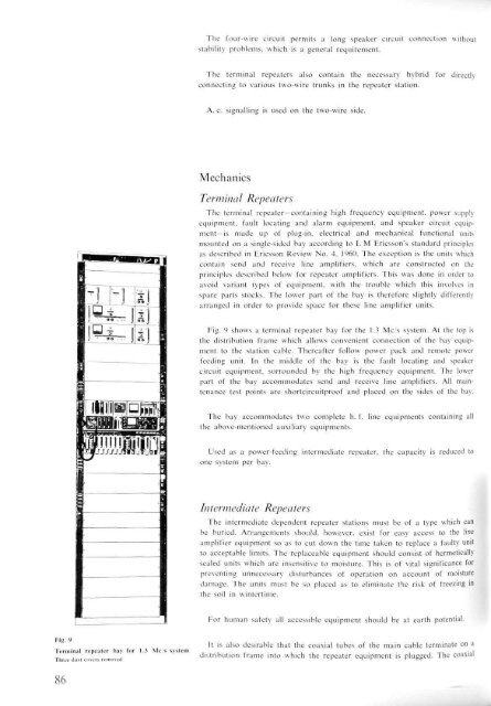
Fig. 9 shows a terminal repeater bay for the 1.3 Mc/s system. At the top is<br />
the distribution frame which allows convenient connection of the bay equipment<br />
to the station cable. Thereafter follow power pack and remote power<br />
feeding unit. In the middle of the bay is the fault locating and speaker<br />
circuit equipment, surrounded by the high frequency equipment. The lower<br />
part of the bay ac<strong>com</strong>modates send and receive line amplifiers. All maintenance<br />
test points are shortcircuitproof and placed on the sides of the bay.<br />
|§MigBW[|<br />
The bay ac<strong>com</strong>modates two <strong>com</strong>plete h. f. line equipments containing all<br />
the above-mentioned auxiliary equipments.<br />
WRMJIJdjM^jf'Jnt<br />
i '1<br />
•<br />
•<br />
•<br />
I<br />
•<br />
: <br />
Used as a power-feeding intermediate repeater, the capacity is reduced to<br />
one system per bay.<br />
Intermediate Repeaters<br />
The intermediate dependent repeater stations must be of a type which can<br />
be buried. Arrangements should, however, exist for easy access to the line<br />
amplifier equipment so as to cut down the time taken to replace a faulty unit<br />
to acceptable limits. The replaceable equipment should consist of hermetically<br />
sealed units which are insensitive to moisture. This is of vital significance for<br />
preventing unnecessary disturbances of operation on account of moisture<br />
damage. The units must be so placed as to eliminate the risk of freezing in<br />
the soil in wintertime.<br />
For human safety all accessible equipment should be at earth potential.<br />
Fig. 9<br />
It is also desirable that the coaxial tubes of the main cable terminate on a<br />
Terminal repeater bay for 1.3 Mc s system ...... , • . , , , • • , , T-U ovist<br />
distribution frame into which the repeater equipment is plugged. The coaxiai<br />
v<br />
l<br />
Three dust covers removed<br />
"<br />
r bb<br />
86


