

1 - ericssonhistory.com
1 - ericssonhistory.com
1 - ericssonhistory.com

Create successful ePaper yourself
Turn your PDF publications into a flip-book with our unique Google optimized e-Paper software.
The curves show that the small-diameter coaxial cable standardized by<br />
C.C.I.T.T. with the diameter ratio 1.18/4.43 mm has an optimal system size<br />
of N ~ 900 channels when the annual costs are considered. On the basis<br />
solely of first cost, the nearest optimal system size will be about 2700<br />
channels.<br />
For purposes of conversion a 2700-channel system will under all circumstances<br />
be economically advantageous <strong>com</strong>pared with the installation of new<br />
cable.<br />
The saving in per cent of the first cost for three sizes of system through the<br />
use of small-diameter coaxial cable instead of the heavier 2.6/9.5 mm cable has<br />
been calculated below. The costs of laying of the cable have not been included<br />
since they are virtually independent of the diameter of the coaxial tubes.<br />
System<br />
Saving<br />
300<br />
50%<br />
960<br />
20%<br />
1700<br />
0<br />
Another factor which makes small-diameter coaxial cable attractive also<br />
on heavy-traffic routes is that the cost of standby equipment in a multitube<br />
small-diameter coaxial system is small <strong>com</strong>pared with the conditions in a<br />
normal coaxial cable system with small number of tubes.<br />
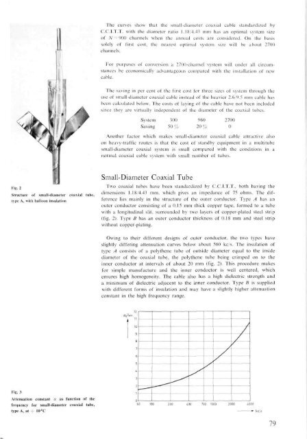
Fig. 2<br />
Structure of small-diameter<br />
type A, with balloon insulation<br />
coaxial tube,<br />
Small-Diameter Coaxial Tube<br />
Two coaxial tubes have been standardized by C.C.I.T.T., both having the<br />
dimensions 1.18/4.43 mm, which gives an impedance of 75 ohms. The difference<br />
lies mainly in the structure of the outer conductor. Type A has an<br />
outer conductor consisting of a 0.15 mm thick copper tape, formed to a tube<br />
with a longitudinal slit, surrounded by two layers of copper-plated steel strip<br />
(fig. 2). Type B has an outer conductor thickness of 0.18 mm and steel strip<br />
without copper-plating.<br />
Owing to their different designs of outer conductor, the two types have<br />
slightly differing attenuation curves below about 500 kc/s. The insulation of<br />
type A consists of a polythene tube of outside diameter equal to the inside<br />
diameter of the coaxial tube, the polythene tube being crimped on to the<br />
inner conductor at intervals of about 20 mm (fig. 2). This procedure makes<br />
for simple manufacture and the inner conductor is well centered, which<br />
ensures high homogeneity. The cable also has a high dielectric strength and<br />
a minimum of dielectric adjacent to the inner conductor. Type B is supplied<br />
with different forms of insulation and may have a slightly higher attenuation<br />
constant in the high frequency range.<br />
Fig. 3<br />
Attenuation constant y. as function of the<br />
frequency for small-diameter coaxial tube,<br />
type A, at + 10°C<br />
79


