Create successful ePaper yourself
Turn your PDF publications into a flip-book with our unique Google optimized e-Paper software.
Page<br />
1<br />
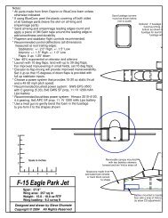
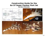
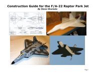
F-<strong>14</strong> <strong>Tomcat</strong> <strong>Park</strong> <strong>Jet</strong><br />
Made In Washington State, USA!<br />
Kit# 3DF0F<strong>14</strong><br />
A High Performance Electric <strong>Jet</strong><br />
About This Construction Manual<br />
This booklet divides the construction into sub-assemblies; wing, fuselage, etc. Please read each section carefully before starting<br />
on that particular sub-assembly. There is a complete description of all parts under “Kit Contents” Please check to make sure your kit<br />
is complete. We are human, and occasionally miss something! If you have trouble identifying a part, or are missing something, please<br />
contact us and we can help.<br />
During the construction process the steps will outline what part to use. We have used actual pictures instead of unclear or often<br />
inaccurate illustrations to assist in the building process. This manual is intended for English users, and all measurements are made in<br />
standard units (inch, foot, etc.)<br />
Customer Service:<br />
Should you experience a problem building or flying this kit, we recommend you see your hobby shop first. If you are unable to solve<br />
the problem, feel free to contact: Further updates can be found on our website<br />
support@3DFoamy.com or online at www.3DFoamy.com<br />
This product is sold with exclusion of all warrantee, expressed or implied, statutory or otherwise.<br />
Pilot assumes all risk in building and operating this model. Do not operate if you are not an experienced modeler. Refer to<br />
and abide by AMA rules at www.modelaviation.com for regulations on Radio Control Models.<br />
© 2005 3D Foamy All Rights Reserved
Page<br />
2<br />
Kit Contents<br />
Part No. QTY. Dimensions Description<br />
007201a 1 Laser Cut Foam Foam Kit Parts A 6mm<br />
007201b 1 Laser Cut Foam Foam Kit Parts B 6mm<br />
007201c 1 Laser Cut Foam Foam Kit Parts C 6mm<br />
007201d 1 Laser Cut Foam Foam Kit Parts D 3mm<br />
007207 2 ¼ Nylon Bolts Wing swing bolts<br />
007206 1 (1)2-56 rod and (4)ends Swing wing pushrods<br />
007205 2 EZ links and pushrods Stabilator control parts<br />
007204 1 Laser cut 1/8” ply Plywood parts<br />
007202 2 .21” dia carbon tube Wing Spar<br />
007203 2 .21” carbon tube Stabilator spar/pivot<br />
007209 1 Laser Cut Plastic Control Horns/Doublers<br />
007210 1 Intro Sheet Getting Started Paper<br />
© 2005 3D Foamy All Rights Reserved
Page<br />
3<br />
□ 5 Ch radio system with 3-4 micro<br />
servos (HS-55 or similar) and micro<br />
receiver (Hitec Electron 6)<br />
□ Odorless Medium CA and<br />
accelerator. (Accelerator a must)<br />
Additional items you will need<br />
□ Motor (Himax 2015-4100 gearbox<br />
recommended)<br />
□ Connectors – Dean’s Ultra<br />
connectors are recommend for this<br />
model.<br />
□ Props (APC 9x6 recommended)<br />
□ Speed Control (Castle Creations<br />
Phoenix 25 recommended)<br />
□ 5 or 15 minute Epoxy □ Li-Poly Battery pack (1200-1500<br />
mah 3s1p recommended)**<br />
□ 3M Satin tape<br />
□ Extra high quality flexible hook up<br />
wire (16 gauge minimum)<br />
□ Li-Po Charger (Must be approved<br />
for Li-Po Cells!)<br />
□ Foam-safe contact glue (sold at<br />
most craft stores)<br />
Building supplies that make it easy<br />
□ Scissors □ Sand paper (150, 220, and 320 grit) □ Steel straight edge<br />
□ Razor saw □ Hobby Knife and extra blades □ Small building square<br />
□ Rubbing Alcohol □ Pencil and Pen □ Wire cutters<br />
□ Soldering iron □ Assorted screwdrivers □ Paper towels<br />
Definitions<br />
• LE- Leading Edge • CA- “Super Glue” • Brushless- New<br />
motors, no brushes,<br />
computer controlled.<br />
• TE- Trailing Edge • Brushed- Normal • Li-Poly-New Battery<br />
motor type, brushes, packs. Lithium<br />
can, magnets.<br />
Polymer (Cell phone<br />
battery)<br />
• 3S1P- 3 cells, 1 Pack<br />
• 3S2P- 3 cells, 2 packs<br />
• ESC—Electronic<br />
Speed Control<br />
• “C” Rating- the maximum charge or discharge<br />
rate of the cell. A 1000 mah pack rated at “10C”<br />
could provide a 10 amp discharge. All packs<br />
should be charged at “1C”(1000mah pack should<br />
charge at 1000 mah max. That means a 1 hour<br />
charge time.<br />
© 2005 3D Foamy All Rights Reserved
General Construction Notes<br />
1) Start by thoroughly reading this manual, and also look carefully at the plans. Many items<br />
are addressed more clearly on the plans.<br />
2) Normal CA will melt the foam, but odorless CA can be used. Accelerator is a must! It will<br />
take hours to dry on its own…<br />
3) PAINTING: Painting is not necessary. However, test the paint on a small scrap first. If<br />
masking for painting, use blue low adhesive tape or else when the tape is removed, the<br />
film will inadvertently be removed as well. When removing the tape, pull the tape<br />
towards any edge of the film so that the film is not pulled loose. You will likely need to<br />
put striping tape between the colors as they can bleed under the tape. An alternative to<br />
painting is colored packing tape. It is easy to use, self adhesive, and low cost.<br />
Page<br />
4<br />
Electronics Notes<br />
There are many choices to make when deciding on your power system and it can get confusing. For good performance, it’s important<br />
that the motor/gearing/prop used for this model generate at least 18-20 oz static thrust and a 45-50 mph pitch speed. A program like<br />
MotoCalc (www.motocalc.com) is invaluable for analyzing potential power systems and is highly recommended.<br />
The recommended power setups for this model are summarized below. Both of these setups utilize efficient high-power brushless<br />
motors, and will provide excellent jet-like performance. Note that brushed motors (such as the GWS EPS-350) will not provide good<br />
performance on this model and are not recommended.<br />
Standard Brushless Setup<br />
Motor: Himax 2015-4100 with "B gearing (4.4:1) or Himax 2015-5300 with “C” gearing (5.3:1)<br />
Battery: High performance 1200-1500 mAh 11.1V lithium-polymer pack capable of supplying at least 12 amps continuous. Note that<br />
7.4V lithium-polymer battery packs will not provide adequate performance on this model and should not be used.<br />
Speed Control: Castle Creations Phoenix 25 brushless controller<br />
Prop: APC 9x6 or 9x7.5 slow flyer<br />
This setup will produce 21 oz static thrust with 50 mph top speed and will provide exhilarating performance with nearly 1:1 thrust-toweight<br />
ratio (if you build light).<br />
© 2005 3D Foamy All Rights Reserved
Page<br />
5<br />
Brushless Outrunner Setup<br />
Motor: Axi 2212/26, Hacker A20-20L, 22L<br />
Battery: High performance 1200-1500 mAh 11.1V lithium-polymer pack capable of supplying at least 12 amps continuous. Note that<br />
7.4V lithium-polymer battery packs will not provide adequate performance on this model and should not be used.<br />
Speed Control: Castle Creations Phoenix 25 brushless controller<br />
Prop: APC 9x6 or 9x7.5 slow flyer<br />
This setup will produce 19 oz static thrust with 50 mph top speed. It doesn’t have quite as much power as the recommended Himax<br />
motors above, but the Axi outrunner is extremely smooth and quiet in operation and has none of the gearbox noise of the Himax. This<br />
motor is a pleasure to fly. Note that you’ll need a GWS stick mount adapter to mount the Axi and Hacker to the hardwood motor mount<br />
on this model.<br />
Please note this model was designed to be a lightweight parkflyer and was not designed to handle<br />
extremely powerful motor systems and high flying weights. Thus, avoid the temptation to overpower this<br />
model unless you have the knowledge and experience to modify the design appropriately!<br />
© 2005 3D Foamy All Rights Reserved
Page<br />
6<br />
About your Plane<br />
Your ai<strong>rc</strong>raft was designed by computer (CAD) for accuracy and construction ease. All parts have been precision cut on a CNC laser<br />
cutting system right here in the 3D Foamy shop!<br />
The foam used in your kit is the best quality available. Depron is very light and stiff and is also very forgiving and easy to paint.<br />
However, because we want weight at the minimums, the planes are still somewhat fragile, so a little care can go a long way.<br />
Note that this model is intended for experienced modelers, and is not suitable for beginners. If you’re comfortable flying a fast sport<br />
aerobatic airplane, you can probably handle this model.<br />
I hope that you are going to enjoy building and flying this plane as much as I have! Best of luck, and don’t hesitate to e-mail me with any<br />
questions or comments at help@3DFoamy.com.<br />
P.S. If you think I can improve or clarify something in this manual, please let me know!<br />
Construction<br />
Before Beginning<br />
All parts have been accurately cut on a computer-controlled laser cutting<br />
machine. Remove the ai<strong>rc</strong>raft parts from the foam packing sheets. Cut the<br />
tabs loose with a razor blade for best results.<br />
This model can be built using the following types of adhesives:<br />
• Epoxy<br />
• Odorless cyanoacrylate (CA) with accelerator<br />
• UHU Creativ for Styrofoam (or UHU POR) (pictured at left)<br />
• 3M 77 spray adhesive<br />
• Hot glue gun<br />
• ProBond (or Gorilla Glue)<br />
To minimize weight, try to use as little epoxy as possible on this model,<br />
saving it for only critical joints such as wing spars and motor mounts. For<br />
best results, the majority of construction should use a lightweight and quickdrying<br />
adhesive such as CA, UHU Creativ, and 3M 77.<br />
© 2005 3D Foamy All Rights Reserved
Page<br />
1. Begin assembly with the forward fuselage. Lay the two fuselage sides<br />
down flat on the work bench and glue the foam doublers to the locations<br />
shown on the plans. Be sure to make two mirror image parts—a left side<br />
and a right side.<br />
7<br />
After the glue has dried, glue the three fuselage bulkheads to one of the<br />
fuselage sides at the locations shown, making sure they are perpendicular.<br />
2. Next glue the two fuselage sides together. Set the fuselage sides upright<br />
and flat on the workbench, apply glue to the edge of the bulkheads, and<br />
push the sides together.<br />
After the glue has dried, glue this assembly to the fuselage bottom piece<br />
as shown.<br />
Glue the two forward fuselage top pieces in forward of the canopy (not<br />
shown in this photo).<br />
© 2005 3D Foamy All Rights Reserved
Page<br />
3. Laminate the nose cone pieces together using 3M 77 spray adhesive.<br />
Then glue the assembled nosecone block to the forward fuselage as<br />
shown (5 minute epoxy recommended).<br />
8<br />
Once the glue has dried, carve the nose cone to shape. Start by tracing<br />
the top view on the top of the block and cutting the block to that outline.<br />
Begin with coarse sandpaper (60 grit) to rough out the basic shape, then<br />
move to progressively finer sandpaper (first 150, then 220 grit) to do the<br />
final shaping.<br />
Make the canopy using the same procedure. Note the canopy has two<br />
smaller sill pieces that glue on to each side of the canopy to form the lower<br />
sill.<br />
© 2005 3D Foamy All Rights Reserved
Page<br />
4. Begin assembly of the inlets. Be sure to make two mirror-image inlets!<br />
9<br />
First glue the small plastic stabilizer support discs to each side around the<br />
laser cut ci<strong>rc</strong>les for the stabilators, Then glue all the foam support strips<br />
as shown to both the inboard and outboard inlet sides. Glue the taileron<br />
servo doubler to the inboard inlet side.<br />
Use a heat gun to gently form the required curves in these pieces. Hold<br />
each piece next to the inlet bottom piece to judge the curvature required.<br />
© 2005 3D Foamy All Rights Reserved
Page<br />
5. Tack glue the three temporary inlet bulkheads to one side (these will be<br />
removed later), and then tack glue the two inlet sides together.<br />
10<br />
Next glue the inlet bottom piece on. To make sure the inlets are<br />
assembled perfectly square, hook the sides over a bench as shown and<br />
hold the top of the inlets flat against the bench as the glue dries.<br />
After the glue has dried, sand the corners of the inlets to a well-rounded<br />
shape.<br />
© 2005 3D Foamy All Rights Reserved
6. Glue the inlet diverters to the fuselage sides. Note the bottom of the<br />
diverter butts up against the step in the fuselage bottom piece.<br />
Page<br />
11<br />
7. Laminate the five motor mount pieces together using 3M 77. Note the<br />
tabbed piece goes in the middle. Then sand the assembly to a tapered<br />
shape as shown.<br />
Laminate the motor mount with the 3 pieces from the ply sheet, glue in the<br />
motor mount using 5 minute epoxy.<br />
© 2005 3D Foamy All Rights Reserved
Page 12<br />
8. Sand the forward fuselage to the contours shown. It’s important to do this<br />
now before you glue the inlets to the side of the fuselage, since the inlets<br />
will block access to the aft part of the fuselage. Sand the bottom edges to<br />
a ci<strong>rc</strong>ular shape, and then sand the top edges down to the feathered<br />
shape shown on the diagram at left. Note how the tops of the fuselage<br />
sides blend into the canopy sill.<br />
© 2005 3D Foamy All Rights Reserved
Page 13<br />
9. Next glue the inlets to each side of the fuselage. Note that the tabs on the<br />
fuselage bottom piece slide into corresponding slots in the inlet sides,<br />
which automatically ensures proper alignment. But you’ll need to make<br />
sure the inboard forward top edges of the inlets are flush with the top of<br />
the aft fuselage (the area held together with blue tape in the bottom picture<br />
at left). Note that the motor mount also has tabs and slots to ensure<br />
proper alignment as well. 15 minute epoxy is highly recommended for this<br />
step, both for strength and to give you time to get everything aligned<br />
before the glue sets. Set the fuselage upside down on the workbench<br />
(hooked over an edge with the inlet tops sitting flat against the bench) as<br />
the glue cures to ensure this assembly is perfectly flat on top. This is<br />
important because the wing spar box will span across the top and the<br />
wings will fold up on top as well.<br />
After the glue has cured, remove all of the temporary bulkheads inside the<br />
inlets.<br />
© 2005 3D Foamy All Rights Reserved
Page<br />
10. Next we’ll build the wing sweep mechanism. Begin by removing all the<br />
laser-cut parts. Touch-up sand the pieces where necessary.<br />
<strong>14</strong><br />
11. Glue the doublers to both ends of the spar box top and bottom pieces.<br />
Laminate the two spacer pieces and glue them in place on top of the<br />
doublers on one side. Then glue the balsa shear webs in place on the<br />
same side. Medium viscosity CA is recommended for all of these joints.<br />
Next laminate the two swing arm pieces together with CA. Be sure to<br />
make two mirror-image parts—the piece with the control arm goes on<br />
bottom for each side.<br />
NOTE: Picture shows prototype with servo mount attached, this has been<br />
changed since and it is no longer one piece.<br />
© 2005 3D Foamy All Rights Reserved
Page 15<br />
12. Test fit the top and bottom spar box pieces together. Sand the balsa shear<br />
webs as required until you get a perfect fit. Then glue the top and bottom<br />
pieces together with CA.<br />
Now drill the four holes for the nylon bolt wing pins to size—one in each<br />
end of the spar box and one in each swing arm. Use a drill press if at all<br />
possible to ensure the holes are perfectly perpendicular! I left them a tad<br />
undersized so you can drill to fit perfectly, I left the top holes a bit<br />
undersized and threaded the bolts into them so they stay in place.<br />
Test fit the swing arms and nylon bolts in place, and check to see if they<br />
rotate smoothly. You want them to fit tightly but still rotate smoothly. Sand<br />
the swing arms as required to thin them down until they turn smoothly.<br />
Note that you can also adjust the tension of the swing arms by tightening<br />
the nylon nut and bolt, so it’s OK if the swing arms end up a little loose.<br />
© 2005 3D Foamy All Rights Reserved
Page 16<br />
13. Cut the carbon tube wing spars to length and test fit the swing arms and<br />
spars into the wing, trimming as required. Then glue the swing arms and<br />
spars in place using epoxy (note that the side with the control arm goes<br />
down on the swing arms). Place wax paper and heavy books on top of the<br />
wings as the epoxy cures to ensure everything stays perfectly flat. After<br />
the glue cures, put a strip of 3M Satin tape over the top and bottom of the<br />
spar to help hide the joint and provide a smooth wing surface.<br />
Now sand the wing to shape. Sand the leading edge to a well-rounded<br />
shape and sand the trailing edge down to a tapered shape from the top.<br />
This will result in a thin flat-bottom airfoil. Put a strip of Satin tape over the<br />
leading edge to provide durability and smoothness.<br />
<strong>14</strong>. Glue the 3 1/8” thick spacer blocks in the bottom center of the wing swing<br />
box. However, check the fit of your servo first to see if this thickness puts<br />
the servo arm at the same height as the control arms on the wing swing<br />
arms. You may need to use a thicker or thinner spacer depending on your<br />
servo. 3/8” is what worked for the HS-81MG servo used in the prototype.<br />
© 2005 3D Foamy All Rights Reserved
Page 17<br />
15. Attach the 1/8” lite-ply servo arm extension to the nylon servo arm with two<br />
screws as shown. You may need to experiment to find the exact hole<br />
locations that result in both wings swinging identically forward to back—<br />
and those locations may not be symmetrical. I found that the left wing<br />
needs a little longer moment arm than the right wing to swing equally. If<br />
one wing swings more than the other, simply increase the moment arm on<br />
that side. The already laser cut positions are what worked (after much<br />
experimenting) with the HS-81MG servo used in the prototype.<br />
Also note that if this horn seems weak to you (only .25” wide), that’s by<br />
design! This servo arm is intended to be the weak link in the wing swing<br />
mechanism. That way, if you catch a wing on landing, this horn will break<br />
before anything else in the system breaks. This is good because this horn<br />
is easy and quick to replace via the hatch in the top of the fuselage. This<br />
design has already paid off for me—I had a crash landing in one of the<br />
early flights and this arm broke just as intended, preventing any further<br />
damage to the wing or swing mechanism!<br />
16. Glue 1/8” lite-ply strengthener to the bottom of the servo tray as shown.<br />
Then check the fit of the servo and trim as required. When done, the<br />
assembly should look like the picture on bottom.<br />
A Hitec HS-81MG servo was used on the prototype, which works OK but is<br />
definitely straining in this application. An HS-85MG servo is a little<br />
heavier but provides more torque and will work better for most and is<br />
recommended. But whatever servo you choose, make sure to use a<br />
METAL geared servo since a nylon geared servo is very likely to strip.<br />
© 2005 3D Foamy All Rights Reserved
17. Glue the servo tray on the bottom of the spacer.<br />
Page<br />
18<br />
Make and install the wing swing pushrods using 2-56”” threaded rods with<br />
steel clevises on each side. Silver solder the inside clevices onto the rod.<br />
18. Now plug the servo into your receiver and test the wing swing mechanism,<br />
adjusting it as required until it works perfectly. You want both wings to<br />
swing easily and also swing the same amount. If one wing swings more<br />
than the other, adjust the control throws on the servo control arm. If the<br />
wings tend to bind, sand the swing arms down in thickness. Use the<br />
buzzing of the servo to tell you where the problems are—it’ll buzz heavily if<br />
it encounters something it doesn’t like!<br />
For reference, there are mechanical stops on both ends of the wing swing<br />
travel. The step in the wing trailing edges should just touch the back of the<br />
wing swing spar box when the wings are swept fully aft. And the control<br />
arms on the wing swing arms should hit the forward side of the spacer<br />
inside the spar box when the wings are fully forward. Use those extremes<br />
to gauge how much swing is required.<br />
Note that a key feature of this design is that it is independent from the rest<br />
of the airframe. Thus, everything can be tested and adjusted to work<br />
perfectly BEFORE you install it.<br />
© 2005 3D Foamy All Rights Reserved
Page 19<br />
19. Test fit the wing swing box onto the fuselage. The forward side of the spar<br />
box butts up against the step in the inlet tops. Cut clearance holes as<br />
shown for the wing pushrods on the top of each inlet side (4 total). Be<br />
sure to make those holes wide enough to clear the pushrods throughout<br />
the entire swing of the wings.<br />
Use this forward wing strake piece as a guide to help you glue the spar<br />
box in with perfect alignment. First test fit the wing strake piece to ensure<br />
it fits well and trim as required. Then draw centerlines on everything<br />
(strake, fuselage, spar box) to help align everything. After you’re confident<br />
everything fits well and is aligned, glue in the spar box and strake together<br />
using epoxy.<br />
Note that the wings are easily removable on this model, even after it’s<br />
finished. To remove the wing, just pull out the nylon bolts at the wing pivot<br />
and unsnap the clevis on the servo arm (using needle-nose pliers through<br />
the access hatch on top). Then slide the wing out, being careful to pull the<br />
pushrods carefully through the clearance holes. Reverse this procedure to<br />
put the wing back on, being careful to guide the wing pushrods back<br />
through the clearance holes. Note there’s no need to ever take the clevis<br />
off the wing control arm—use the clevis at the servo instead.<br />
© 2005 3D Foamy All Rights Reserved
Page<br />
20. Next install the tailerons. Each taileron has a .21” diameter carbon spar<br />
that pivots inside two small pieces of laser cut plastic which are glued to<br />
the foam inside the inlets. The ply discs keep the rod from moving side to<br />
side.<br />
20<br />
Begin by sanding the tailerons to shape. Sand the leading edges to a wellrounded<br />
shape and the trailing edges to a tapered shape. Put a strip of<br />
3M Satin tape on the leading edges to provide durability and smoothness.<br />
Also put a few layers of Satin tape on the forward root of the tailerons to<br />
increase strength.<br />
If you have not already, glue the plastic discs onto the fuselage sides.<br />
Make sure to put the carbon rods in the bearings while the epoxy cures to<br />
ensure everything is aligned. Then glue the spars into the tailerons using<br />
epoxy.<br />
After the glue is cured, slide the carbon rods through the plastic bearings<br />
and slide the end stops and control horns onto each rod (but don’t glue<br />
them yet).<br />
Hitec HS-55 micro servos were used on each taileron in the prototype<br />
(shown at bottom) and are the bare minimum servos that will work.<br />
However, a slightly stronger mini servo is recommended, such as the JR<br />
241 shown in the middle picture. Don’t use a larger servo than that,<br />
though, since it may make the model tail heavy.<br />
Install the servo and use the pushrod of 1/16” music wire. An EZ<br />
connector provides a strong control linkage that’s easy to adjust. Set the<br />
length of the pushrod so that the servo arm and taileron control arm are<br />
perfectly vertical. I you can CA, or use tape to hold the servos in place,<br />
combined with the friction from a tight-fitting hole in the foam.<br />
Adjust as required until everything is aligned—the control arms are<br />
vertical, the tailerons are level, and the end stops fit snugly against the<br />
inlet sides. Then put a few drops of CA on the end stops and taileron<br />
control horns to secure them in place. NOTE: it may work easier to put the<br />
control horns the opposite way as shown, facing down to clear the rudder<br />
© 2005 3D Foamy All Rights Reserved
Page<br />
doublers.<br />
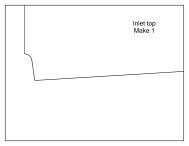
21. Glue the vertical tail support doublers to the inside of each inlet top piece,<br />
making left and right versions. Then cut the slot for the vertical tails at a<br />
roughly 5 degree cant angle (canted outboard). Use a heat gun to form<br />
the small curve in the aft end for the exhaust nozzle.<br />
21<br />
Glue the inlet top pieces onto the inlets. Note that the forward edge of<br />
these pieces butts up against the rear edge of the wing spar box.<br />
© 2005 3D Foamy All Rights Reserved
Page 22<br />
22. Install the speed control and battery extension wiring. Note that the<br />
battery extension wiring should be twisted and then wrapped with<br />
aluminum foil to reduce RF interference. In the photo here, the speed<br />
control is installed inside the airplane. However, I later learned (the hard<br />
way) that the speed control must be installed OUTSIDE the airplane to<br />
provide cooling and prevent shutdown due to overheating. So cut a hole in<br />
the bottom of the fuselage and route the wiring so that the speed control is<br />
located on the bottom outside of the airplane (see bottom picture).<br />
Laminate the 2 parts for the wing cover center support and glue in place<br />
on the back of the wing spar box (shown in the top picture).<br />
23. Sand the vertical tails to shape, giving the leading edges a round shape<br />
and the trailing edges a tapered shape.<br />
If you’re installing rudders, cut those out and hinge them with Satin tape.<br />
Glue the tails in place using epoxy, canting them outboard at a 5 degree<br />
angle.<br />
© 2005 3D Foamy All Rights Reserved
Page 23<br />
24. If you’re installing rudders on this model, install the control runs now. I<br />
used Sullivan light flexible cable pushrods, with 1/32” music wire soldered<br />
on the rudder end and Dubro micro EZ connectors on the servo end. Note<br />
the two small pieces of scrap foam that support the cables near the servo.<br />
Rudders are nice to have and are useful during aerobatics and very low<br />
speed maneuvering. But they are not required for this model to fly well<br />
and may not be worth the effort for most.<br />
25. Install the center aft fuselage top piece using epoxy.<br />
26. Now install all the remaining wing strake pieces, including the aft upper<br />
wing cover (2 pieces) and the forward and aft lower strake pieces.<br />
Note that the forward lower wing strake pieces may need to be notched<br />
inside a little to clear the wing swing pushrods.<br />
Install the turtledeck sides and top. Note that the turtledeck sides are<br />
glued on at a roughly 15 degree angle (canted inboard) to give them that<br />
characteristic F-<strong>14</strong> shape.<br />
© 2005 3D Foamy All Rights Reserved
27. Sand the wing strake and turtledeck to shape as shown.<br />
Page<br />
24<br />
To reduce the friction of the wing swing mechanism, place a single layer of<br />
packing tape on the insides of the wing slot (top only) and on the top and<br />
bottom of the wing root (but only where it contacts the wing slot). Bare<br />
foam and plywood joints may swing freely on the bench, but once the wing<br />
gets deflected with 1g flight loads these joints need packing tape to keep<br />
the friction down.<br />
© 2005 3D Foamy All Rights Reserved
Page<br />
25<br />
28. Cut an access hole for the wing swing servo as shown. Also cut the<br />
access hole for the receiver (not shown here, but shown on the plans) and<br />
install the receiver. Tape can be used to hold both hatches on.<br />
© 2005 3D Foamy All Rights Reserved
Page 26<br />
29. The canopy is removable to allow easy access to the battery compartment.<br />
It is held in place with two bamboo skewers forward (toothpicks or carbon<br />
rod could also be used) that slide into matching holes in the forward<br />
bulkhead, and two small strips of Velcro aft that are mounted to short<br />
pieces of ¼” balsa triangle stock.<br />
Cut two 2” lengths of bamboo and sharpen both ends. Stick the bamboo<br />
into the foam at the front of the canopy so that only ½” protrudes and glue<br />
into place.<br />
After the glue dries, push the canopy onto the airplane so that the<br />
protruding ends poke holes into the forward bulkhead. Then glue the<br />
Velcro mounts to the fuselage sides as shown on the plans and attach the<br />
matching Velcro pieces to the mounts and to the canopy.<br />
30. Install the motor and plug it into the speed control leads.<br />
Install the prop. Using a prop-saver is a very good idea to prevent damage<br />
to the prop or airplane during landings.<br />
© 2005 3D Foamy All Rights Reserved
31. CONGRATULATIONS! Your model is now complete.<br />
Page<br />
27<br />
The model can be painted using standard acrylic craft paint (available at<br />
most craft stores), applied with either a brush or airbrush. Wipe the foam<br />
with rubbing alcohol before painting to remove any grease or dirt. Rough<br />
areas such as the canopy and nosecone should be filled with lightweight<br />
wall spackling compound thinned with water, which fills the holes and can<br />
be sanded to a very smooth finish (with minimal weight gain). Try to<br />
minimize weight as much as possible when selecting your paint scheme.<br />
I hope you enjoy this model as much as I have!<br />
© 2005 3D Foamy All Rights Reserved
Additional Photos<br />
Here are some additional photos of the prototype F-<strong>14</strong> <strong>Tomcat</strong> <strong>Park</strong> <strong>Jet</strong> for reference<br />
Page<br />
28<br />
© 2005 3D Foamy All Rights Reserved
Page<br />
29<br />
Flight Setup<br />
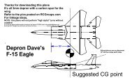
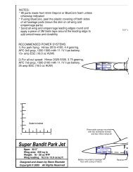
1. The center of gravity location is critical on this model. Make sure to locate it as shown on the plans for your first flights,<br />
which is 0.5” ahead of the wing pivot bolts. Depending on how your model is built and set up, you may need to add ballast to<br />
the nose to achieve this CG (the prototype model required about 0.75 oz of ballast in the nose). After you’ve gained some<br />
experience flying this model and have it trimmed out, the CG can be moved as far aft as the wing pivots for improved<br />
maneuverability.<br />
2. Set up the flight controls to provide the following recommended deflections (all dimensions are measured at the root trailing<br />
edge):<br />
• Tailerons (pitch): +/- 1.5" (-40% expo)<br />
• Tailerons (roll): +/- 1.75" (-40% expo)<br />
• Rudder: +/- 7/8" (-30% expo)<br />
Note that these settings will work fine with the wing in all sweep positions. The F-<strong>14</strong> is naturally quick in pitch and sluggish in<br />
roll with the wings fully unswept, but quick in roll and sluggish in pitch with the wings fully swept aft. However, these control<br />
deflections provide a good compromise for both cases so that you don’t have to flick a switch every time you change the wing<br />
sweep.<br />
3. Note that the F-<strong>14</strong> has a natural aerodynamic tendency to pitch down slightly when the wings are swept from forward to aft.<br />
To counter this and keep the airplane trimmed, a custom mix must be set up in the transmitter to automatically add a small<br />
amount of up elevator trim as the wing is swept aft. This mix should be set up so that swinging from full forward to full aft<br />
sweep provides 1/4" trailing edge up stabilator (about 5% mix rate if using the recommended control deflections). You may<br />
need to experiment with your particular model to find the mix that works best, but once you’ve got this adjusted properly you<br />
can swing the wings forward and aft at will at any time during the flight and the airplane will always stay perfectly trimmed.<br />
4. Recommended hand launch procedure: Grip the airplane by either the left or right inlet near the CG, set about 75% throttle,<br />
and throw the model moderately hard straight ahead and parallel to the ground. Be careful to keep your hand away from<br />
the prop as you throw it! It’s important to launch at less than full throttle to minimize prop torque effects at launch, which<br />
could cause the model to roll left immediately after you throw it. Full throttle can be added right after launch once the airplane<br />
has some speed.<br />
5. Landing: Remember to ALWAYS release the elevator control right before touchdown during landings, since the<br />
forward stabilator tips can dig into to grass or soft ground—which can significantly damage the model and/or<br />
stabilator servos! A good hard flare a couple feet off the ground will slow the model down to a very low airspeed, then simply<br />
release the elevator and let the model plop gently onto the ground. Also remember to pull the throttle back to zero just before<br />
touchdown so that the propeller and/or motor mount is not damaged on landing.<br />
© 2005 3D Foamy All Rights Reserved
Page<br />
30<br />
Repairs<br />
Should the inevitable happen, here are some tips:<br />
• Cracks in the foam are fixed with some foam safe CA. Just use accelerator to speed up the process.<br />
• Almost anything is repairable. I cracked my plane in 5 pieces, and everyone thought it was finished. 15 minutes later it was<br />
flying. Just take some CA, accelerator and packing tape to the field with you!<br />
If you are using more then 2 bottles of CA a day for fixes… order some more kits!<br />
Best of flying to you, and I hope you have enjoyed building this kit as much as I have designing them!<br />
Remember to send your pictures and videos to post on the website!!!<br />
“I live for this stuff!”<br />
3D Foamy<br />
support@3DFoamy.com.com<br />
www.3DFoamy.com<br />
© 2005 3D Foamy All Rights Reserved