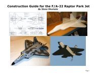
Construction Guide for the Su-37 Super Flanker Park Jet
Construction Guide for the Su-37 Super Flanker Park Jet
Construction Guide for the Su-37 Super Flanker Park Jet

Create successful ePaper yourself
Turn your PDF publications into a flip-book with our unique Google optimized e-Paper software.
Page 1
Introduction<br />
Welcome to <strong>the</strong> <strong>Su</strong>-<strong>37</strong> park jet! This model was designed <strong>for</strong> twin Littlescreamers <strong>Park</strong> <strong>Jet</strong> (LSPJ) motors and features a working 3-<br />
axis thrust vectoring (TV) system, just like <strong>the</strong> real <strong>Su</strong>-<strong>37</strong>. With <strong>the</strong> TV system off, this model handles extremely well in <strong>the</strong> air and is<br />
very predictable, maneuverable, and easy to fly. But with <strong>the</strong> TV system on, it can do wingtip flips, incredibly tight turns, and wild<br />
tumbling maneuvers just like <strong>the</strong> real <strong>Su</strong>-<strong>37</strong>. The TV system also provides excellent controllability at ultra low airspeeds and high<br />
alpha. With <strong>the</strong> twin LSPJs, <strong>the</strong> top speed of this model is in <strong>the</strong> neighborhood of 80 mph and <strong>the</strong> thrust-to-weight ratio is between 1.4<br />
and 1.7, providing unlimited vertical. Amazing per<strong>for</strong>mance <strong>for</strong> an electric model! The counter-rotating propellers also result in no prop<br />
torque, which provides very smooth launches and more jet-like handling qualities.<br />
The 3-axis thrust vectoring system provides roll, pitch, and yaw—both motors gimbal up/down toge<strong>the</strong>r <strong>for</strong> pitch, opposite <strong>for</strong> roll, and<br />
differential throttles provides yaw. The prototype model used separate servos <strong>for</strong> <strong>the</strong> tailerons and <strong>the</strong> thrust vectoring, <strong>for</strong> 4 servos<br />
total. This allows turning <strong>the</strong> TV system on and off at will (via a switch on <strong>the</strong> transmitter) and also allows easily adjusting <strong>the</strong> trims and<br />
rates of <strong>the</strong> TV system separately from <strong>the</strong> stabilators. However, this model was also designed so that <strong>the</strong> builder can eliminate <strong>the</strong> two<br />
stabilator servos and just slave <strong>the</strong> stabilators and TV toge<strong>the</strong>r mechanically. This eliminates <strong>the</strong> cost and weight of <strong>the</strong> extra pair of<br />
servos and also greatly simplifies <strong>the</strong> transmitter programming. To do this, just run a pushrod from each servo to <strong>the</strong> stabilator control<br />
horn (note <strong>the</strong> control must be installed pointing down instead of up as shown on <strong>the</strong> plans), and <strong>the</strong>n run a second pushrod from <strong>the</strong><br />
control horn to <strong>the</strong> TV mechanism. Note this simplified TV setup will require a lot of manual adjustments in <strong>the</strong> linkages to ensure <strong>the</strong><br />
stabilators and TV are properly aligned, especially once <strong>the</strong> airplane is trimmed.<br />
Note <strong>the</strong>re are many options <strong>for</strong> how this model can be built, including:<br />
• With or without canard – The plans show all <strong>the</strong> modifications required to convert this <strong>Su</strong>-<strong>37</strong> to one of <strong>the</strong> original non-canard<br />
<strong>Su</strong>-27 or <strong>Su</strong>-30 variants. All that's required is to delete <strong>the</strong> canard, modify <strong>the</strong> strake contours, and modify <strong>the</strong> vertical tail outline.<br />
The changes required to do this are shown in red on <strong>the</strong> plans.<br />
• Twin motors or single motor – This design can be easily adapted <strong>for</strong> a single centerline motor, which could be done with or<br />
without thrust vectoring (in this case it would be single-axis or pitch only). Note <strong>the</strong> upcoming Littlescreamers <strong>Su</strong>per <strong>Park</strong> <strong>Jet</strong><br />
Special motor would be an excellent match <strong>for</strong> a single-motor version. The changes required to do this are also shown on <strong>the</strong><br />
plans.<br />
• With or without thrust vectoring – The TV system provides amazing maneuverability on this model but also adds quite a bit of<br />
weight, cost and complexity. For those that want a simpler version, this model can be built without <strong>the</strong> TV system and will still be<br />
a great-flying park jet. Ano<strong>the</strong>r option is to go with <strong>the</strong> simplified TV system described above.<br />
• Flight control options – There are a wide range of flight control options on this model. To actuate everything (stabilators,<br />
flaperons, rudders, canard, thrust vectoring, throttles) would require 9 channels and up to 8 servos! But on <strong>the</strong> o<strong>the</strong>r hand, this<br />
model could also be flown just fine using tailerons and throttle only—3 channels and 2 servos. The setup used on <strong>the</strong> prototype<br />
model (and described in this manual) is in between <strong>the</strong>se extremes, utilizing tailerons, rudder, thrust vectoring, and twin throttles,<br />
<strong>for</strong> 7 channels and 5 servos.<br />
Page 2
Building Tips<br />
This model can be built using <strong>the</strong> following types of adhesives:<br />
• Epoxy (with or without microballons)<br />
• Odorless cyanoacrylate (CA) with accelerator<br />
• UHU Creativ <strong>for</strong> Styrofoam (or UHU POR)<br />
• 3M 77 spray adhesive<br />
• Hot glue gun<br />
• ProBond (or Gorilla Glue)<br />
To minimize weight, try to use as little epoxy as possible on this model,<br />
saving it <strong>for</strong> only critical joints such as wing spars and motor mounts. You<br />
can also mix microballons into <strong>the</strong> epoxy to reduce weight considerably and<br />
help it fill gaps better. The majority of construction should use a lightweight<br />
and quick-drying adhesive such as foam-safe CA, UHU Creativ, or 3M 77. I<br />
personally use 3M 77 and UHU Creativ (pictured at left) <strong>for</strong> <strong>the</strong> majority of<br />
construction since <strong>the</strong>y are strong, dry very quickly, and sand well.<br />
You’ll notice that 3M Satin tape is called out several times in <strong>the</strong>se<br />
instructions, since it works very well <strong>for</strong> hinges, leading edge protection, and<br />
general streng<strong>the</strong>ning. When purchasing, make sure to get 3M Satin tape<br />
(sometimes called 3M Gift tape), which is sold in <strong>the</strong> purple container. The<br />
common 3M Scotch tape sold in a green container doesn’t work nearly as<br />
well, nor does common packing tape.<br />
Begin construction by cutting out all of <strong>the</strong> paper parts templates with<br />
scissors, trimming <strong>the</strong>m to within approximately 1/8” of <strong>the</strong> lines. Then test fit<br />
all of <strong>the</strong> templates onto <strong>the</strong> foam sheet, trying to minimize wasted foam as<br />
much as possible. Once you’re satisfied with <strong>the</strong> arrangement, remove each<br />
template individually and spray <strong>the</strong> back of <strong>the</strong> template LIGHTLY with 3M 77<br />
spray adhesive. Then replace <strong>the</strong> template onto <strong>the</strong> same spot on <strong>the</strong> foam<br />
sheet. Repeat <strong>for</strong> every template.<br />
After all <strong>the</strong> templates are tacked onto <strong>the</strong> foam, cut out all <strong>the</strong> pieces by<br />
cutting on <strong>the</strong> lines with a SHARP hobby knife. To help keep track of <strong>the</strong><br />
parts, keep <strong>the</strong> paper templates on each piece until you’re ready to use it.<br />
Page 3
1. Begin by assembling <strong>the</strong> thrust vectoring motor mounts. This step is<br />
optional—you may choose to install straight motor sticks if you don’t want<br />
to incorporate thrust vectoring. If so, just cut <strong>the</strong> hardwood motor mount to<br />
<strong>the</strong> length you need and skip <strong>the</strong> rest of this step.<br />
Cut <strong>the</strong> 3/8" square hardwood motor mount stick into two lengths—a 3 3/8"<br />
main stick and a 1 1/2" movable portion. Drill a 1/8" dia. hole in <strong>the</strong> main<br />
stick to fit <strong>the</strong> 1/8" O.D. brass bearing tube (top photo), and <strong>the</strong>n glue <strong>the</strong><br />
tube in place with thin CA. Cut a small chamfer in <strong>the</strong> lower edge as<br />
shown. Then wrap <strong>the</strong> aft end of this stick with a layer of packing tape to<br />
ensure a smooth low friction surface.<br />
Sand <strong>the</strong> inside surface of <strong>the</strong> two 1/8” plywood side plates to make <strong>the</strong>m<br />
as smooth as possible. Trim <strong>the</strong> aft edge of <strong>the</strong> movable motor mount<br />
stick as shown on <strong>the</strong> plans, and <strong>the</strong>n glue on both side plates using epoxy<br />
or CA. After <strong>the</strong> glue is dry, drill <strong>the</strong> pivot hole through <strong>the</strong> top of both side<br />
plates at <strong>the</strong> same time, making sure it is exactly perpendicular to <strong>the</strong><br />
plates (using a drill press is highly recommended).<br />
The assembled motor mount is shown in <strong>the</strong> middle photo. The movable<br />
portion pivots around a 3-48 bolt, and <strong>the</strong> system is actuated via a pushrod<br />
and Dubro micro ball link on <strong>the</strong> bottom. Make sure <strong>the</strong> system pivots<br />
smoothly, and sand or trim as required. For extra strength and security,<br />
install a small bolt and nut across <strong>the</strong> lower side plates and movable<br />
mount stick (bottom photo).<br />
Repeat <strong>for</strong> <strong>the</strong> second motor mount, making it a mirror-image of <strong>the</strong> first.<br />
IMPORTANT NOTE: It is important that <strong>the</strong> thrust line of <strong>the</strong> motor runs<br />
directly through <strong>the</strong> pivot pin. This will minimize strain on <strong>the</strong> thrust<br />
vectoring servo and also prevent pitch trim changes with throttle setting.<br />
The parts provided were designed specifically <strong>for</strong> <strong>the</strong> Littlescreamers <strong>Park</strong><br />
<strong>Jet</strong> Special motor with <strong>the</strong> stock 3/8” stick mount. If you use a different<br />
motor and mount, you may need to make new custom side plates out of<br />
1/8” plywood that raise or lower <strong>the</strong> movable motor mount stick to realign<br />
<strong>the</strong> thrust line with <strong>the</strong> pivot pin. If so, this won’t be difficult since <strong>the</strong><br />
design of <strong>the</strong>se plates is very simple--just trim or extend <strong>the</strong> square upper<br />
edge as required.<br />
Page 4
2. Now begin assembly of <strong>the</strong> nacelle sides. Start by gluing <strong>the</strong> 3/4" square<br />
1/16" plywood stabilizer bearing supports in place on each nacelle side<br />
using epoxy, at <strong>the</strong> location shown in <strong>the</strong> top picture at left. Note you'll<br />
need to cut a small notch in <strong>the</strong> top corner to clear <strong>the</strong> motor mount stick<br />
on <strong>the</strong> two outboard nacelle sides. Make sure to make mirror-image left<br />
and right side pieces (middle photo).<br />
Next carefully align <strong>the</strong> left and right sides of each nacelle and tape <strong>the</strong>m<br />
toge<strong>the</strong>r back to back (with <strong>the</strong> plywood squares on <strong>the</strong> outsides). Then<br />
drill a clearance hole <strong>for</strong> <strong>the</strong> stabilizer pivot rods through both support<br />
plates at <strong>the</strong> same time (bottom photo). Use a drill press if at all possible<br />
to ensure <strong>the</strong> hole is perfectly perpendicular. The stabilizer pivot rods<br />
should be able to turn freely in <strong>the</strong>se holes, but with as little play as<br />
possible.<br />
Page 5
3. Glue <strong>the</strong> nacelle side doublers to <strong>the</strong> inboard nacelle sides at <strong>the</strong> locations<br />
shown on <strong>the</strong> plans (top photo). 3M77 spray works very well <strong>for</strong> this. Note<br />
<strong>the</strong>re are two layers of doublers, which will allow sanding <strong>the</strong>se corners<br />
down to a very large radius once <strong>the</strong> model is assembled. Make sure to<br />
make left- and right-side pieces.<br />
Glue <strong>the</strong> nacelle side doublers to <strong>the</strong> outboard nacelle sides at <strong>the</strong><br />
locations shown on <strong>the</strong> plans, using <strong>the</strong> same procedure as be<strong>for</strong>e (middle<br />
photo).<br />
Glue <strong>the</strong> main motor mount sticks in place on <strong>the</strong> outboard nacelle sides<br />
using epoxy. Make sure <strong>the</strong> chamfered edge is on bottom when installing.<br />
Optional: For less drag and a cleaner appearance, use a sharp hobby<br />
knife to cut a 45 angle on <strong>the</strong> inside edges of all <strong>the</strong> nacelle side doublers<br />
(bottom photo).<br />
Page 6
4. Test fit <strong>the</strong> movable section of <strong>the</strong> motor mounts and ensure <strong>the</strong>y swing<br />
freely. Trim and sand if required.<br />
Install <strong>the</strong> thrust vectoring servos. A strong (40+ oz/in torque) metalgeared<br />
servo is required since a plastic-geared servo could get stripped if<br />
<strong>the</strong> prop hits <strong>the</strong> ground during landings. The prototype used a Hitec HS-<br />
85MG servo, which worked very well. Use double-sided tape to attach <strong>the</strong><br />
servo to <strong>the</strong> nacelle sides, and <strong>the</strong>n glue in scraps of foam all around <strong>the</strong><br />
servo to hold it securely and eliminate play. Lastly use thick CA and<br />
accelerator to glue <strong>the</strong> servo firmly in place.<br />
Cut <strong>the</strong> pushrods to length and install.<br />
Plug <strong>the</strong> servos into a receiver and test <strong>the</strong> thrust vectoring mechanisms to<br />
ensure <strong>the</strong>y work properly. Set <strong>the</strong> throws up so that <strong>the</strong> motor mounts<br />
deflect about 30 degrees up and down.<br />
5. Next build <strong>the</strong> wing. Lay <strong>the</strong> wing down over wax paper on a flat surface<br />
and use 30 minute epoxy to glue in <strong>the</strong> carbon tube wing spar. Mixing<br />
some microballons into <strong>the</strong> epoxy is recommended to reduce weight and<br />
help <strong>the</strong> glue fill gaps better (ProBond also works well). Place wax paper<br />
and some heavy books on top of <strong>the</strong> wing to hold it perfectly flat as <strong>the</strong><br />
glue cures.<br />
After <strong>the</strong> glue has cured, sand <strong>the</strong> leading to a well-rounded shape and <strong>the</strong><br />
trailing edge to a tapered shape. Apply a strip of 3M Satin tape around <strong>the</strong><br />
entire leading edge <strong>for</strong> smoothness and improved durability.<br />
Page 7
6. Place <strong>the</strong> wing on a flat surface, and <strong>the</strong>n glue <strong>the</strong> nacelle sides in place<br />
as shown, fitting <strong>the</strong> tabs in <strong>the</strong> nacelles to <strong>the</strong> pre-cut slots in <strong>the</strong> wing.<br />
Note <strong>the</strong> outboard nacelle sides are bent slightly inboard to <strong>for</strong>m a gentle<br />
curve (though no heat-<strong>for</strong>ming is required). Use four temporary 90 degree<br />
angle pieces of scrap foam to hold <strong>the</strong> nacelle sides perpendicular as <strong>the</strong><br />
glue dries. Also note pins can be used to hold everything toge<strong>the</strong>r while<br />
<strong>the</strong> glues dries. A gap-filling glue such as epoxy with microballons or<br />
ProBond is recommended <strong>for</strong> this step.<br />
Page 8
7. Next build and install <strong>the</strong> vertical tail and side rails. Begin by sanding <strong>the</strong><br />
leading edge of <strong>the</strong> vertical tails to a well-rounded shape, and <strong>the</strong> trailing<br />
edge to a tapered shape. Apply a strip of 3M Satin tape to <strong>the</strong> leading<br />
edge <strong>for</strong> smoothness and durability<br />
Cut a slot in <strong>the</strong> vertical tail <strong>for</strong> <strong>the</strong> 1/32" plywood spar (note <strong>the</strong> location<br />
shown on <strong>the</strong> plans is different from <strong>the</strong> photo shown at left—one of <strong>the</strong><br />
lessons learned after building <strong>the</strong> prototype model!). Place <strong>the</strong> vertical tail<br />
over wax paper on a flat surface and <strong>the</strong> glue <strong>the</strong> aux spar in place using<br />
epoxy.<br />
Laminate <strong>the</strong> two fuselage side rails toge<strong>the</strong>r using 3M77 (two pieces<br />
toge<strong>the</strong>r <strong>for</strong> each side). Then glue <strong>the</strong> laminated side rails to <strong>the</strong> vertical<br />
tail piece as shown (top photo). Once <strong>the</strong> glue is dry, sand <strong>the</strong> side rails to<br />
a scale tapered and rounded shape (middle photo). See photos of <strong>the</strong> real<br />
<strong>Su</strong>-27/<strong>Su</strong>-<strong>37</strong> <strong>for</strong> guidance on how <strong>the</strong>se are shaped.<br />
Glue <strong>the</strong> completed vertical tail/side rail pieces to each side of <strong>the</strong> aft<br />
fuselage with epoxy (bottom photo). Use temporary 90 degree triangle<br />
scraps of foam on top of <strong>the</strong> wing (not shown here) to ensure <strong>the</strong> vertical<br />
tail is perpendicular to <strong>the</strong> wing. Note <strong>the</strong> rounded aft end of <strong>the</strong> side rails<br />
sits flush with <strong>the</strong> holes <strong>for</strong> <strong>the</strong> stabilator pivot rods.<br />
Page 9
8. Now begin <strong>the</strong> <strong>for</strong>ward fuselage assembly. Glue <strong>the</strong> <strong>for</strong>ward fuselage<br />
doublers to <strong>the</strong> <strong>for</strong>ward fuselage sides using 3M 77. Make sure to make<br />
left- and right-side pieces. Note that double thickness doublers are used<br />
throughout to allow sanding <strong>the</strong> <strong>for</strong>ward fuselage to a very rounded shape<br />
after assembly.<br />
9. Using a heat gun, gently heat and bend <strong>the</strong> <strong>for</strong>ward fuselage sides to <strong>the</strong><br />
shape shown in <strong>the</strong> photo at left and on <strong>the</strong> plans. For guidance in<br />
shaping this piece, use <strong>the</strong> turtledeck top piece to trace an outline on <strong>the</strong><br />
top of <strong>the</strong> wing with a Sharpie marker (shown in <strong>the</strong> photo at left). Then<br />
simply bend <strong>the</strong> fuselage sides to match that outline. Drawing a centerline<br />
on <strong>the</strong> wing will also help keep <strong>the</strong> fuselage properly aligned.<br />
Page 10
10. Next install <strong>the</strong> <strong>for</strong>ward fuselage onto <strong>the</strong> wing, including <strong>the</strong> sides and<br />
four bulkheads (you can install all of <strong>the</strong>se parts at once). Use epoxy with<br />
microballons (or ProBond) and use pins and masking tape to keep<br />
everything aligned and in place. Glue <strong>the</strong> <strong>for</strong>ward fuselage sides to <strong>the</strong><br />
TOP of <strong>the</strong> wing first, <strong>the</strong>n let <strong>the</strong> glue dry.<br />
11. Now glue <strong>the</strong> <strong>for</strong>ward fuselage sides to <strong>the</strong> bottom of <strong>the</strong> wing. It will help<br />
to draw an outline on <strong>the</strong> bottom of <strong>the</strong> wing first (simply trace <strong>the</strong> <strong>for</strong>ward<br />
fuselage bottom piece) to provide guidance on how much to bend <strong>the</strong>se<br />
parts in.<br />
Page 11
12. Glue on <strong>the</strong> <strong>for</strong>ward fuselage top and turtledeck tops (top photo). I found it<br />
easier to NOT laminate <strong>the</strong> turtledeck tops be<strong>for</strong>e installing—just glue <strong>the</strong><br />
first one, let <strong>the</strong> glue dry, and <strong>the</strong>n glue <strong>the</strong> second one on top of <strong>the</strong> first).<br />
Glue on <strong>the</strong> <strong>for</strong>ward fuselage bottom piece (bottom photo).<br />
13. Laminate <strong>the</strong> nosecone pieces toge<strong>the</strong>r using 3M 77 adhesive. Then glue<br />
<strong>the</strong> nosecone block to <strong>the</strong> front of <strong>the</strong> fuselage.<br />
Once <strong>the</strong> glue has dried, sand <strong>the</strong> nosecone to shape. Start by tracing <strong>the</strong><br />
top outline of <strong>the</strong> nosecone onto <strong>the</strong> foam (using <strong>the</strong> provided template)<br />
and cut it to shape with a long knife or saw. Begin with coarse sandpaper<br />
(100 grit) to rough out <strong>the</strong> basic shape, <strong>the</strong>n move to a finer sandpaper<br />
(220 grit) to do <strong>the</strong> final shaping. End with 320 grit sandpaper to do <strong>the</strong><br />
final polish sanding and provide a very smooth surface.<br />
Page 12
14. Laminate all of <strong>the</strong> canopy pieces toge<strong>the</strong>r using 3M 77 adhesive. Note<br />
how <strong>the</strong> two sill pieces are attached to <strong>the</strong> outside edges of <strong>the</strong> block.<br />
Once <strong>the</strong> glue has dried, sand <strong>the</strong> canopy to shape. Start by tracing <strong>the</strong><br />
top outline of <strong>the</strong> canopy onto <strong>the</strong> foam (using <strong>the</strong> provided template) and<br />
use that to guide <strong>the</strong> shaping. Begin with coarse sandpaper (100 grit) to<br />
rough out <strong>the</strong> basic shape, <strong>the</strong>n move to a finer sandpaper (220 grit) to do<br />
<strong>the</strong> final shaping. End with 320 grit sandpaper to do <strong>the</strong> final polish<br />
sanding and provide a very smooth surface.<br />
Note that custom-molded clear canopies are also available from<br />
www.6mmflyrc.com.<br />
Page 13
15. Next make and install <strong>the</strong> wing fillets. Begin by laminating <strong>the</strong> three fillet<br />
pieces toge<strong>the</strong>r using 3M77. Then rough sand <strong>the</strong> fillets to a smooth<br />
concave shape using a rounded sander (I simply wrapped sandpaper<br />
around an epoxy bottle as shown in <strong>the</strong> middle photo). Start with coarse<br />
sandpaper and work your way to finer grits.<br />
Once <strong>the</strong> fillets are roughed to shape, glue <strong>the</strong>m to <strong>the</strong> wing/fuselage.<br />
Then apply generous amounts of lightweight spackling compound all<br />
around <strong>the</strong> fillets and sand to a smooth well-blended shape. See photos of<br />
<strong>the</strong> real <strong>Su</strong>-27/<strong>Su</strong>-<strong>37</strong> <strong>for</strong> guidance in shaping <strong>the</strong>se. It takes quite a bit of<br />
time to properly shape <strong>the</strong>se fillets, but take your time to do it right—<strong>the</strong>y<br />
are a very integral and recognizable feature of <strong>the</strong> <strong>Su</strong>-27/<strong>Su</strong>-<strong>37</strong> airplanes!<br />
Page 14
16. Next make and install <strong>the</strong> canards. Bare foam canards will not be strong<br />
enough and must be streng<strong>the</strong>ned. There are several ways this could be<br />
done, including installing hard balsa around all edges of <strong>the</strong> canard,<br />
fiberglassing <strong>the</strong> entire canard, or installing 1/32" plywood spars and<br />
covering with Satin tape (as shown in <strong>the</strong> top photo). Chose <strong>the</strong> method<br />
you prefer.<br />
Begin by sanding <strong>the</strong> canard pieces to a symmetrical airfoil shape. Then<br />
add <strong>the</strong> streng<strong>the</strong>ning using your selected method. Next cut slots in <strong>the</strong><br />
canards <strong>for</strong> <strong>the</strong> plywood dihedral braces and <strong>the</strong>n glue <strong>the</strong>m in place with<br />
epoxy as shown.<br />
Cut matching slots in <strong>the</strong> wing <strong>for</strong> <strong>the</strong> plywood dihedral braces and <strong>the</strong>n<br />
glue <strong>the</strong> completed canards in place with epoxy as shown.<br />
Page 15
17. Next install <strong>the</strong> stabilators. Sand <strong>the</strong> leading edge of <strong>the</strong> stabilators to a<br />
well-rounded shape, and <strong>the</strong> trailing edge to a tapered shape. Apply a<br />
strip of 3M Satin tape to <strong>the</strong> leading edge <strong>for</strong> smoothness and durability.<br />
Lay <strong>the</strong> stabilators over wax paper on a flat surface and glue <strong>the</strong> carbon<br />
tube pivots into place using epoxy (top photo).<br />
Note <strong>the</strong> hardware required <strong>for</strong> <strong>the</strong> stabilators (second photo from top).<br />
The carbon tubes pivot inside <strong>the</strong> plywood supports in <strong>the</strong> nacelle sides.<br />
Two plywood end stops butt up against each support to keep <strong>the</strong> pivot<br />
tube from sliding left/right. A plywood control arm is installed to allow a<br />
pushrod connection to <strong>the</strong> servo. Putting a small piece of packing tape<br />
over <strong>the</strong> plywood supports in <strong>the</strong> nacelles to minimize friction with <strong>the</strong> end<br />
stop bearings is recommended.<br />
Slide <strong>the</strong> carbon pivot tube through <strong>the</strong> outboard ply support, and <strong>the</strong>n<br />
slide on an end stop, control horn, and <strong>the</strong> o<strong>the</strong>r end stop (third photo from<br />
top). Push <strong>the</strong> pivot rod through to <strong>the</strong> inboard ply support. Once<br />
everything is in place and aligned, glue <strong>the</strong> end stops into place with epoxy<br />
or thick CA, but don’t glue <strong>the</strong> control horn yet.<br />
Install <strong>the</strong> stabilator servos using a similar procedure as <strong>the</strong> thrust<br />
vectoring servos (double-sided tape, foam block supports, thick CA<br />
rein<strong>for</strong>cement). Then install <strong>the</strong> pushrods. Once everything is aligned<br />
properly, glue <strong>the</strong> plywood control horn to <strong>the</strong> carbon tube using epoxy or<br />
CA.<br />
Repeat <strong>for</strong> <strong>the</strong> o<strong>the</strong>r stabilator.<br />
Page 16
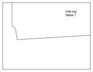
18. Next install <strong>the</strong> inlet diverter pieces. Glue <strong>the</strong> 3mm Depron triangular inlet<br />
diverter center pieces to <strong>the</strong> 3mm Depron inlet diverter top pieces (top<br />
photo). Make sure to make left and right hand pieces.<br />
Glue <strong>the</strong> above assembly into place at <strong>the</strong> front of <strong>the</strong> inlets (bottom two<br />
photos). Then glue <strong>the</strong> 6mm Depron internal inlet top piece in place<br />
directly behind <strong>the</strong> diverter pieces .<br />
Page 17
19. Laminate <strong>the</strong> aft fuselage top and bottom spine pieces using 3M 77. Then<br />
sand to a well rounded shape, and taper <strong>the</strong> back end to a spike (top<br />
photo).<br />
Sand <strong>the</strong> decorative nacelle top pieces to a rounded shape with fea<strong>the</strong>red<br />
edges (top photo).<br />
Glue <strong>the</strong> top spine, bottom spine, and nacelle tops to <strong>the</strong> aft fuselage<br />
(middle and bottom photos).<br />
Page 18
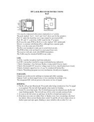
20. Install <strong>the</strong> receiver, speed controls, and wiring. There are many ways you<br />
could do this, but I chose to install <strong>the</strong> receiver in <strong>the</strong> <strong>for</strong>ward left nacelle<br />
(top photo), and one speed control in each nacelle flush with <strong>the</strong> inboard<br />
nacelle sides (bottom photo). Try to locate everything as far <strong>for</strong>ward as<br />
possible since this model tends to be tail-heavy. Twist all <strong>the</strong> ESC wires<br />
toge<strong>the</strong>r to help reduce electromagnetic interference, and tape all wiring<br />
down flat against <strong>the</strong> foam to keep <strong>the</strong>m from flopping around in flight. To<br />
connect <strong>the</strong> components on opposite sides of <strong>the</strong> airplane, I simply ran <strong>the</strong><br />
wiring across <strong>the</strong> bottom of <strong>the</strong> wing and <strong>the</strong>n taped <strong>the</strong>m down flat to <strong>the</strong><br />
wing. Although <strong>the</strong>se wires will be visible externally, you can paint over<br />
<strong>the</strong>m later to help hide <strong>the</strong>m.<br />
Note <strong>the</strong> battery extension wires must branch off in a Y to connect to each<br />
speed control. Use 16 ga minimum <strong>for</strong> <strong>the</strong> battery to ESC extensions, and<br />
you can use ei<strong>the</strong>r 16 ga or 18 ga <strong>for</strong> <strong>the</strong> ESC to motor extensions.<br />
Make sure all of <strong>the</strong> electronics work properly be<strong>for</strong>e proceeding to <strong>the</strong><br />
next step, since once <strong>the</strong> nacelle bottoms are glued on you'll have to cut<br />
into <strong>the</strong> model to gain access.<br />
NOTE: Make sure to install <strong>the</strong> speed controls so that <strong>the</strong>y get PLENTY of<br />
airflow <strong>for</strong> cooling. Mounting <strong>the</strong>m inside <strong>the</strong> nacelles as shown is ideal. I<br />
even cut away some of <strong>the</strong> plastic shrink wrap to promote even better<br />
cooling. Cooling is important not just because of <strong>the</strong> heat generated by<br />
<strong>the</strong> motor controller, but even more so <strong>for</strong> <strong>the</strong> integrated BEC circuitry<br />
since this model requires 4 servos (and most speed controls are only rated<br />
<strong>for</strong> 3 or 4 servos). Providing ample cooling to <strong>the</strong> BEC will allow it operate<br />
<strong>the</strong> servos safely and help prevent premature shutdowns due to<br />
overheating. Note you could use a separate and more powerful BEC<br />
component instead, but that would add weight and cost.<br />
Page 19
21. Sand <strong>the</strong> bottom of <strong>the</strong> nacelles flush with a long sander. Then glue on<br />
<strong>the</strong> nacelle bottoms. Sand <strong>the</strong> nacelle lower edges to a well-rounded<br />
shape.<br />
Page 20
22. Sand <strong>the</strong> balsa wing tip missile rails to shape and glue to <strong>the</strong> wing tips.<br />
23. If incorporating rudders, install <strong>the</strong> rudder control hardware now. Rudders<br />
are not required and this model flies fine without <strong>the</strong>m, but <strong>the</strong>y are helpful<br />
<strong>for</strong> improved control at high alpha and <strong>for</strong> better aerobatics.<br />
Mount <strong>the</strong> servo in a slot in <strong>the</strong> wing on <strong>the</strong> centerline under <strong>the</strong> canopy.<br />
Use <strong>Su</strong>llivan micro flexible cable pushrods, with small pieces of 1/32”<br />
music wire soldered onto <strong>the</strong> rudder end. Make a small hole in <strong>the</strong><br />
fuselage sides <strong>for</strong> <strong>the</strong> pushrod to exit, and <strong>the</strong>n cut a slit in <strong>the</strong> top of <strong>the</strong><br />
wing as shown and push <strong>the</strong> pushrod down into that slit. Then glue <strong>the</strong><br />
pushrod in using thin CA and accelerator. Filler can be added be<strong>for</strong>e<br />
painting to help hide <strong>the</strong>se pushrods.<br />
I used Dubro micro pushrod keepers on <strong>the</strong> rudder horn and Dubro micro<br />
EZ connectors on <strong>the</strong> servo end. Use a 90 degree servo arm and make<br />
sure <strong>the</strong> pushrods connect to <strong>the</strong> servo arm at a 90 degree angle at<br />
neutral (to ensure <strong>the</strong> rudders deflect equally).<br />
Page 21
24. Optional step – If you plan to fly this model aggressively (ei<strong>the</strong>r high<br />
speed, high weight, or aggressive aerobatics or tumbling), it is highly<br />
recommend to install a 1/32" plywood auxiliary spar in each wing as shown<br />
on <strong>the</strong> plans and in <strong>the</strong> photo at left. This spar will significantly streng<strong>the</strong>n<br />
<strong>the</strong> front of <strong>the</strong> wing and prevent it from flexing. Just cut a slot with a<br />
sharp knife into <strong>the</strong> wing and <strong>the</strong>n glue <strong>the</strong> spar in with epoxy.<br />
It is also highly recommended that <strong>the</strong> stabilators be streng<strong>the</strong>ned<br />
chordwise. Just run a 1" wide strip of fiberglass cloth chordwise at <strong>the</strong> root<br />
from front to back and on top and bottom, and adhere <strong>the</strong> cloth with ei<strong>the</strong>r<br />
water-based polyurethane or epoxy.<br />
25. CONGRATULATIONS! Your model is now complete.<br />
The model can be flown as is or can be painted using a variety of paints<br />
(see <strong>the</strong> next step <strong>for</strong> painting advice). I actually recommend test flying<br />
<strong>the</strong> airplane be<strong>for</strong>e painting it to allow making <strong>the</strong> maiden flight at <strong>the</strong><br />
lowest possible weight and to allow you to more easily fix any internal<br />
problems that might arise.<br />
Page 22
PAINTING TIPS - This model can be painted with a wide variety of paints, just<br />
make sure to test compatibility with <strong>the</strong> foam first. The prototype was painted<br />
with standard acrylic craft paint (available at most craft stores), which can be<br />
applied with ei<strong>the</strong>r a brush or airbrush. Here are a few painting tips:<br />
• Wipe <strong>the</strong> entire model with rubbing alcohol be<strong>for</strong>e painting to remove<br />
all grease and dirt.<br />
• Rough areas should be filled with lightweight wall spackling compound<br />
thinned with water, which fills <strong>the</strong> holes and can be sanded to a very<br />
smooth finish with minimal weight gain.<br />
• Primer isn’t required over Depron, but applying a coat of water-based<br />
polyurethane (WBPU) will help seal <strong>the</strong> foam and provide a smoo<strong>the</strong>r<br />
finish. Mixing some microballons or baby powder in with <strong>the</strong> WBPU<br />
will help fill holes even better and improves <strong>the</strong> finish fur<strong>the</strong>r.<br />
• When thinning acrylic paint <strong>for</strong> use in an airbrush, thin roughly 50/50<br />
with windshield wiper fluid. The wiper fluid will allow <strong>the</strong> paint to dry<br />
faster (relative to thinning with water), which reduces <strong>the</strong> chance of<br />
runs. It will not affect <strong>the</strong> finish.<br />
• Decals can be made on a computer and printed onto standard label<br />
paper using an inkjet or color laser printer.<br />
Good luck, and I hope you enjoy this model as much as I have!<br />
Page 23
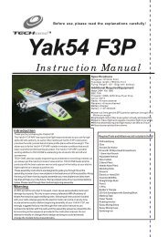
Additional Photos For Reference<br />
Page 24
Flight Setup<br />
1. Below is a chart that summarizes all of <strong>the</strong> channel assignments and mixes used on <strong>the</strong> prototype model (utilizing a Futaba 9C<br />
transmitter). Note that if you don't have a programmable or 7 channel transmitter, you can just build <strong>the</strong> mechanically slaved TV<br />
version. That eliminates <strong>the</strong> need <strong>for</strong> all of <strong>the</strong> custom mixes and 2 additional channels.<br />
<br />
<br />
<br />
2. Adjust <strong>the</strong> flight controls to provide <strong>the</strong> following recommended deflections (all measured at <strong>the</strong> root trailing edge):<br />
Stabilators (pitch): +/- 1.5" (-30% expo)<br />
Stabilators (roll): +/- 1.5" (-30% expo)<br />
Rudder: +/- 0.75"<br />
Thrust vectoring: +/- 30 degrees (mixed with elevator)<br />
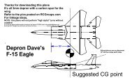
3. Start with <strong>the</strong> CG at 6.1” ahead of <strong>the</strong> centerline of <strong>the</strong> carbon tube wing spar (see <strong>the</strong> plans). Depending on how your model is<br />
set up, some ballast may be required in <strong>the</strong> nose to achieve this CG (<strong>the</strong> prototype required 1.25 oz ballast on <strong>the</strong> final painted<br />
model). This is a relatively conservative <strong>for</strong>ward CG location, great <strong>for</strong> making first flights. You can move <strong>the</strong> CG aft <strong>for</strong> more<br />
Page 25
maneuverability later as desired.<br />
4. To hand launch this model, grip <strong>the</strong> airplane on one of <strong>the</strong> nacelles just behind <strong>the</strong> CG, apply about 75% throttle, and throw it<br />
overhand moderately hard, straight ahead, and slightly nose up. Make sure to keep your hand away from <strong>the</strong> prop as you throw<br />
it! With twin LSPJ motors this model has a lot of power, and full throttle launches aren't required (plus launching at a somewhat<br />
lower power setting will give you more time to react after you've released <strong>the</strong> model).<br />
5. You’ll find this model is surprisingly docile and predictable in <strong>the</strong> air and has no bad habits. But with <strong>the</strong> TV on it is capable of<br />
amazing aerobatics!<br />
6. Belly landings are easy to do with this model, but remember to ALWAYS release <strong>the</strong> elevator control right be<strong>for</strong>e touchdown to<br />
prevent <strong>the</strong> <strong>for</strong>ward stabilator tips from digging into to <strong>the</strong> grass or ground—which can significantly damage <strong>the</strong> model and/or<br />
stabilator servo! Also remember to pull <strong>the</strong> throttle back to zero just be<strong>for</strong>e touchdown so that <strong>the</strong> propeller and/or motor mount is<br />
not damaged on landing.<br />
7. For much more in<strong>for</strong>mation about this model, check out <strong>the</strong> online discussion thread on RCGroups at <strong>the</strong> link below:<br />
http://www.rcgroups.com/<strong>for</strong>ums/showthread.phpt=666686<br />
Page 26
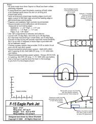
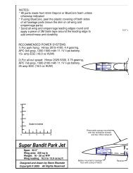
Specifications<br />
Wing area: 290 sq in<br />
Span: 30.0”<br />
Length: 36.3”<br />
Weight RTF: 22 to 29 oz<br />
Wing loading: 11 to 14 oz/sq ft<br />
Flight controls: Tailerons, rudder (optional), thrust vectoring (optional)<br />
Recommended equipment:<br />
Motor: Two Littlescreamers <strong>Park</strong> <strong>Jet</strong> (LSPJ)<br />
Battery: One Thunder Power 2100 mAh 11.1V Prolite<br />
Prop: APC 6x4 regular and pusher (counter-rotating props)<br />
Speed control: Two Castle Creations Thunderbird 18 or Phoenix 25<br />
Receiver: Castle Creations Berg 7P<br />
Servos: Futaba S3110 on all flight controls, Hitec HS-85MG on thrust vectoring<br />
Page 27