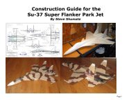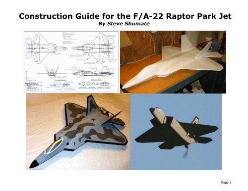
F-22 Scratch Build Construction Guide
F-22 Scratch Build Construction Guide
F-22 Scratch Build Construction Guide

Create successful ePaper yourself
Turn your PDF publications into a flip-book with our unique Google optimized e-Paper software.
Page 1
<strong>Build</strong>ing Tips<br />
This model can be built using the following types of adhesives:<br />
• Epoxy (with or without microballons)<br />
• Odorless cyanoacrylate (CA) with accelerator<br />
• UHU Creativ for Styrofoam (or UHU POR)<br />
• 3M 77 spray adhesive<br />
• Hot glue gun<br />
• ProBond (or Gorilla Glue)<br />
To minimize weight, try to use as little epoxy as possible on this model,<br />
saving it for only critical joints such as wing spars and motor mounts. You<br />
can also mix microballons into the epoxy to reduce weight considerably and<br />
help it fill gaps better. The majority of construction should use a lightweight<br />
and quick-drying adhesive such as foam-safe CA, UHU Creativ, or 3M 77. I<br />
personally use 3M 77 and UHU Creativ (both pictured at left) for the majority<br />
of construction since they are strong and dry very quickly.<br />
3M Satin tape is called out many times in these instructions since it works so<br />
well for hinges, leading edge protection, and general strengthening. Make<br />
sure to get 3M Satin tape (sometimes called 3M Gift tape), which is sold in<br />
the purple container. The common 3M Scotch tape sold in the green<br />
container doesn’t work nearly as well, nor does common packing tape.<br />
Begin construction by cutting out all of the paper parts templates with<br />
scissors, trimming them to within approximately 1/8” of the lines. Then test fit<br />
all of the templates onto the foam sheet, trying to minimize wasted foam as<br />
much as possible. Once you’re satisfied with the arrangement, remove each<br />
template individually and spray the back of the template LIGHTLY with 3M 77<br />
spray adhesive. Then replace the template onto the same spot on the foam<br />
sheet. Repeat for every template.<br />
After all the templates are tacked onto the foam, cut out all the pieces by<br />
cutting on the lines with a SHARP hobby knife. To help keep track of the<br />
parts, keep the paper templates on each piece until you’re ready to use it.<br />
Page 2
1. Begin assembly with the forward fuselage. Start by carefully cutting the<br />
beveled edges on all of the forward fuselage pieces as shown on the<br />
plans. Draw a reference line on each part that’s inset from the edge the<br />
distance indicated on the plans (note you can trace the lines from an<br />
identical part onto the opposite part). Then cut the bevel with a sharp<br />
hobby knife. You can use a straightedge for the straight segments, but the<br />
curved segments will need to be cut by hand. It’s best to practice with<br />
some scrap foam first to get the hang of it before cutting the actual parts.<br />
Be sure to make mirror-image left- and right-side pieces!<br />
The beveled parts should look like the photo at lower left when done<br />
(upper forward fuselage side shown).<br />
Page 3
2. Next form the curvatures in the lower forward fuselage sides. Use a heat<br />
gun to gently heat and soften the foam and then bend them to the shapes<br />
shown. The curves required are a bit complex—there should be one<br />
gradual curve over the entire piece to form the taper of the fuselage (as<br />
seen from the top), and a quick twist at the aft end to match the angled<br />
fuselage sides to the vertical fuselage centerline support. Study these<br />
photos and the photos in the following pages to guide you. The curves<br />
don’t have to be exact since the bulkheads will help form the fuselage as<br />
well once it’s assembled.<br />
Again be sure to make mirror-image left- and right-side pieces.<br />
Page 4
3. Glue the bottom half of the three fuselage bulkheads (the ones with the<br />
notch on top) to one of the lower forward fuselage sides at the locations<br />
shown on the plans, making sure they are perpendicular. Then set the<br />
fuselage sides upright and flat on the workbench, apply glue to the edges<br />
of the bulkheads, and then glue the two fuselage sides together.<br />
After the glue has dried, glue together the aft ends of the fuselage sides as<br />
shown, ensuring they are perfectly vertical. You may need to heat-form<br />
the foam a bit more to get things to align just right.<br />
4. Next build the wing. Cut a slot to fit the carbon wing spar and use 30<br />
minute epoxy to spar into place. Mixing some microballons into the epoxy<br />
is recommended to reduce weight and help the glue fill gaps better (you<br />
can also use ProBond). Place wax paper and some heavy books on top of<br />
the wing to hold it perfectly flat as the glue cures.<br />
After the glue has cured, sand the leading edge of the wing to a wellrounded<br />
shape, as well as the wing tips. Apply a strip of 3M Satin tape<br />
around the leading edge for smoothness and improved durability.<br />
Cut the flaperons free from the wing.<br />
Page 5
5. Laminate the two fuselage centerline support pieces together (3M 77 spray<br />
adhesive recommended). Then cut bevels on the edges of the aft<br />
fuselage sides as indicated on the plans.<br />
Place the wing on a flat surface, and then glue the two aft fuselage sides<br />
and centerline piece onto the bottom of the wing as shown. Use the four<br />
temporary bulkheads provided to ensure the fuselage sides are glued on<br />
at the proper angle. Note pins can be used to hold everything together<br />
while the glues dries. I recommend using a gap-filling glue such as epoxy<br />
with microballons or ProBond for this step.<br />
Remove the temporary bulkheads once the glue dries.<br />
6. Glue the forward fuselage lower assembly in place on the front of the wing.<br />
Make sure the aft end of the forward fuselage mates with the forward edge<br />
of the centerline support piece. Also make sure the curvature is smooth as<br />
the angled forward fuselage sides twist to meet the vertical centerline<br />
support. Some trimming and additional heat-forming will likely be required<br />
to get a smooth curve here.<br />
Also note that the top of the forward fuselage droops down a few degrees<br />
relative to the wing (see bottom photo at left). This is important for<br />
achieving a scale look. As long as the top of the forward fuselage<br />
assembly mates flat against the bottom of the wing, this droop will be set<br />
automatically. Trim the fuselage sides if necessary to achieve this.<br />
Page 6
7. Next assemble the thrust vectoring motor mount. This step is optional—<br />
you may choose to install a straight motor stick if you don’t want thrust<br />
vectoring.<br />
Begin by drilling a hole in the main motor mount stick to fit the aluminum<br />
tube bearing. Then glue the bearing in place with thin CA. Cut a small<br />
chamfer in the lower edge as shown. Wrap the aft end of this stick with a<br />
layer of packing tape to ensure a smooth and low friction surface.<br />
Sand the inside surface of the two 1/8” plywood side plates to make them<br />
as smooth as possible. Then glue both side plates to the movable portion<br />
of the motor mount stick using epoxy. After the glue is dry, drill the pivot<br />
hole through the top of both side plates at the same time, making sure it is<br />
exactly perpendicular to the plates (using a drill press is highly<br />
recommended).<br />
The assembled thrust vectoring system is shown in the lower left photo.<br />
The movable portion pivots around a small bolt, and the system is<br />
actuated via a pushrod and clevis on the bottom. Note that you may need<br />
to trim the lower edges of the motor mount to clear the pushrod and clevis.<br />
Make sure the system pivots smoothly, and sand or trim as required.<br />
IMPORTANT NOTE: It is important that the thrust line of the motor runs<br />
directly through the pivot pin. This will minimize strain on the thrust<br />
vectoring servo and also prevent pitch trim changes with throttle setting.<br />
The parts provided were designed specifically for the Littlescreamers Park<br />
Jet Special motor with the stock 3/8” stick mount. If you use a different<br />
motor and mount, you may need to make new custom side plates out of<br />
1/8” plywood that raise or lower the movable motor mount stick to realign<br />
the thrust line with the pivot pin. If so, this won’t be difficult. The design of<br />
these plates is very simple (just trim or extend the square upper edge), so<br />
it will be easy to make new ones if required.<br />
Page 7
8. Glue the completed motor mount into the slot in the aft fuselage centerline<br />
support, aligning it to a zero-zero thrust line (no left/right or up/down thrust<br />
angle). Use 5 minute epoxy.<br />
After the glue has dried, press a circular notch along the length of the aft<br />
edge of the wing assembly using the aluminum stabilator tube bearings.<br />
Then glue the stabilator bearings into place using 5 minute epoxy. Use<br />
small strips of tape to hold them in place and insert the carbon tube<br />
stabilator pivot into the bearings as the glue dries to make sure they are<br />
perfectly aligned.<br />
9. Sand the leading edge of the stabilators to a well-rounded shape, and the<br />
trailing to a tapered shape. Apply a strip of 3M Satin tape to the leading<br />
edge for smoothness and durability.<br />
Note the hardware required for the stabilator pivots. The single carbon<br />
tube pivots inside two short pieces of aluminum tube. Two end stop<br />
bearings butt up against each aluminum tube to keep the pivot from sliding<br />
left/right. A control arm is also installed to allow a pushrod connection to<br />
the servo. Both the end stops and control arm can be made from spare<br />
nylon servo horns, just drilled out in the center to fit the carbon tube.<br />
Lay the wing assembly down on a flat surface as shown. Slide the carbon<br />
pivot tube, end stops and control horn through the aluminum bearings.<br />
Once everything is in place and aligned, glue the end stops into place with<br />
thin CA (but don’t glue the control horn yet). Then glue both stabilators to<br />
the carbon tube using epoxy (mixing with microballons is recommended).<br />
Page 8
10. Install the stabilator servo into the slot in the fuselage centerline support<br />
(thick CA can be used to hold the servo in place). Make and install a<br />
music wire pushrod to the stab control horn. Once everything is properly<br />
aligned, glue the stab control horn into place using thin CA.<br />
For extra strength, I recommend adding small strips of fiberglass<br />
chordwise to the roots of the stabilators, both top and bottom (see the<br />
plans for size and location). These aren’t required for normal park flying,<br />
but if you intend to fly really fast or land in tall grass they add extra<br />
insurance against structural failure.<br />
11. Next install the thrust vectoring servo and pushrod. A strong (40+ oz/in<br />
torque) metal-geared servo is required since a plastic-geared servo could<br />
get stripped if the prop hits the ground during landings. The prototype<br />
used a Hitec HS-85MG servo, which worked very well. Install the servo in<br />
the slot in the fuselage centerline support, securing it with CA.<br />
Make the pushrod from 1/16” threaded music wire, with a large Z-bend at<br />
the front end to rise up to the servo arm. Install pushrod guides as shown<br />
to eliminate flex in the pushrod (I used scrap carbon fiber tubes from the<br />
stabilator pivot rod). Make sure the pushrods guides are very securely<br />
attached, or a rough landing could break them free. I used small strips of<br />
fiberglass cloth with epoxy over the pushrod guides to provide a very<br />
strong attachment.<br />
Use a steel threaded clevis to connect the pushrod to the motor mount.<br />
Verify that the system moves freely and with minimal slop, and adjust as<br />
required.<br />
Page 9
12. Use a sanding block to lightly sand the top of the lower forward fuselage<br />
until it is flat and even. Then glue on the upper half of each of the three<br />
forward fuselage bulkheads.<br />
Test fit the upper forward fuselage sides, trimming and sanding as<br />
required to get a perfect fit. Note the upper and lower pieces should meet<br />
to form a sharp edge to give it that scale Raptor look. Once satisfied with<br />
the fit, glue the upper forward fuselage sides onto the bulkheads and lower<br />
fuselage sides only (don’t glue the aft part to the top of the wing yet). Use<br />
tape to hold the sides in place as the glue dries.<br />
Page 10
13. Glue bulkheads F4 and F5 to the top of the wing in the locations shown on<br />
the plans. Then glue the aft part of the upper forward fuselage sides to the<br />
top of the wing and the bulkheads. Note how the fuselage sides curve<br />
inward as they run aft—you can heat form the foam slightly to attain this<br />
curvature. Pins can be used to hold the foam in place as the glue cures.<br />
Cut the bevel in the two turtledeck support pieces and then glue them in<br />
place on the top inside edges of the fuselage sides. Then glue the two<br />
turtledeck top pieces in place, one at a time so they can be formed to the<br />
proper curvature. Once the glue is dry, carve and sand the turtledeck<br />
roughly to shape.<br />
Install the forward fuselage top (bottom photo).<br />
Page 11
14. Laminate all of the nosecone and canopy pieces together using 3M 77<br />
adhesive. Then glue the nosecone block to the front of the fuselage.<br />
Once the glue has dried, sand the nosecone to shape. Start by tracing the<br />
top outline of the nosecone onto the foam (using the provided template)<br />
and cut it to shape with a long knife or saw. Begin with coarse sandpaper<br />
(100 grit) to rough out the basic shape, then move to a finer sandpaper<br />
(<strong>22</strong>0 grit) to do the final shaping. End with 320 grit sandpaper to do the<br />
final polish sanding and provide a very smooth surface.<br />
Carve the canopy to shape using a similar procedure.<br />
Page 12
15. Laminate the tail boom pieces together using 3M 77 adhesive. Then glue<br />
the tail boom blocks to the aft fuselage with epoxy. Note that you’ll need to<br />
carve out a small channel in the top of the tail boom blocks first to clear the<br />
aluminum stabilator pivot tubes. Make sure the tail boom blocks fit tight<br />
against the stab pivot tubes, since they provide significant extra strength to<br />
the stabilator pivots.<br />
Next carve the tail booms to shape. Note the outboard sides are angled to<br />
match the aft fuselage sides, the trailing edge is cut at an angle to match<br />
the trailing edge angle of the stabilators, and the trailing edge is sanded<br />
down to a feathered edge to match the stabilators.<br />
Page 13
16. Next install the flaperons. Cut a 45 degree bevel in the leading edge of the<br />
flaperons using a ruler and a hobby knife, and then sand the trailing edges<br />
to a tapered shape. Then hinge the flaperons with strips of 3M Satin tape<br />
top and bottom. Trim as necessary to provide a small and parallel gap<br />
from the leading edge of the stabilators.<br />
Install the flaperon servos, control horns, and pushrods. Note the<br />
pushrods are angled out slightly to allow locating the control horn in a<br />
stronger area of the flaperon.<br />
Glue the vertical tail support pieces under the wing centered over the<br />
vertical tail mounting slots, trimming them if required to clear the flaperon<br />
servos.<br />
17. Sand the leading edge of the vertical tails to a well-rounded shape, and<br />
sand the trailing edges to a tapered shape. Apply a strip of 3M Satin tape<br />
to the leading edge.<br />
If installing rudders, cut them free from the vertical tails. Bevel the leading<br />
edges and hinge with strips of 3M Satin tape.<br />
Cut the vertical tail mounting slots in the aft wing, making the cut at the<br />
proper dihedral angle (use the foam jigs provided as a guide). Cut all the<br />
way through the support pieces mounted underneath the wing.<br />
Glue the vertical tails in place with epoxy (adding microballons is<br />
recommended), using the foam jig pieces to ensure the proper dihedral<br />
angle. Pins can be used to hold the pieces in place as the glue cures.<br />
Page 14
18. If incorporating rudders, install the control hardware now. Rudders are<br />
not required, but are helpful for improved control at high alpha and for<br />
better aerobatics.<br />
Mount the servo in a slot on the centerline just aft of the wing spar. Use<br />
Sullivan micro flexible cable pushrods, with small pieces of 1/32” music<br />
wire soldered onto the rudder end. Use small scraps of foam to support<br />
the pushrods near the servo as shown, and embed the aft end of the<br />
pushrods into a slot the foam in the vertical tail (add epoxy over the slot<br />
later to re-strengthen this area).<br />
I used Dubro micro pushrod keepers on the rudder horn and Dubro micro<br />
EZ connectors on the servo end. Use a 90 degree servo arm and make<br />
sure the pushrods connect to the servo arm at a 90 degree angle at<br />
neutral (to ensure the rudders deflect equally).<br />
Page 15
19. Glue the turtledeck top spine into place on the wing centerline. Then glue<br />
the five turtledeck bulkheads (T1 through T5) into place in the locations<br />
shown on the plans.<br />
If you decided to install rudders, note you’ll need to cut a clearance hole in<br />
the top spine to clear the rudder servo. After cutting this hole, glue a<br />
small scrap of 1/64” plywood over the gap as shown in the bottom picture.<br />
The plywood will allow the fuselage top piece to sit flat along the entire<br />
length of the spine.<br />
Page 16
20. Next shape and install the aft fuselage top piece. This is perhaps the most<br />
challenging aspect of building this model, so take your time. There are<br />
many ways to form the curvature required, but I’ll describe the particular<br />
method I used.<br />
Begin by cutting all the beveled edges in the aft fuselage top piece as<br />
shown on the plans. Next cover most of the bottom of the part with<br />
packing tape (I used yellow packing tape in the top picture at left). The<br />
tape will help keep the piece from wrinkling as you heat form it, and will be<br />
removed when done. Use a heat gun to gently form all the curves as<br />
shown in the middle picture. Test fit the piece onto the model as you go to<br />
determine the exact curves required—use the installed turtledeck<br />
bulkheads to guide how much and where. There are many ways to heat<br />
form the piece, but the method I used was to put the heat gun in a bench<br />
vice (to leave both of my hands free), place a large diameter wood dowel<br />
on my chest, and then stand in front of the heat gun and roll the fuselage<br />
top piece back and forth across the dowel to form nice gentle curves. I<br />
highly recommend that you practice this method on some scrap foam<br />
before attempting it on the actual piece! It takes some practice to learn to<br />
bend the foam gently without wrinkling it. When done heat forming,<br />
remove the packing tape from the bottom of the part.<br />
Test fit the piece on the model and trim as required to get a good fit. The<br />
fit should be close but doesn’t have to be perfect, since you can easily use<br />
spackling compound later to fill any gaps. When satisfied with the fit, glue<br />
the top piece in place. Use a lightweight, sandable, and gap-filling glue<br />
such as epoxy with microballons, ProBond, or aliphatic resin. Use lots of<br />
pins and tape to hold the piece in place as the glue dries (bottom photo at<br />
left).<br />
After the glue dries, use lightweight spackling compound (available at any<br />
home improvement store) to fill any gaps and to create large fillets at the<br />
junction with the fuselage turtledeck and at the junction with the wings.<br />
After the spackling dries, sand the fillets to shape. Note a thin foam<br />
sanding pad works very well for sanding rounded fillets.<br />
Page 17
21. Now install the receiver and speed control. There are many ways you can<br />
do this, but I chose to install the receiver aft and the speed control near the<br />
middle of the plane with short wire extensions to both the motor and to the<br />
battery in the nose. I used a Berg 7P receiver and a Castle Creations<br />
Phoenix 25 ESC, and highly recommend both. Try to locate everything as<br />
far forward as possible since this model tends to be tail-heavy. Twist all<br />
the ESC wires together to help reduce electromagnetic interference, and<br />
tape all wiring down flat against the foam to keep them from flopping<br />
around in flight.<br />
NOTE: It’s very important to install the speed control where it will get<br />
LOTS of cooling airflow. Mounting it inside the inlets as shown is ideal. I<br />
even cut away some of the plastic shrink wrap to promote even better<br />
cooling. Cooling is important not just because of the heat generated by<br />
the motor controller, but even more so for the integrated BEC circuitry<br />
since this model requires 5 servos (and most speed controls are only rated<br />
for 3 or 4 servos). Providing ample cooling to the BEC will allow it operate<br />
more servos safely and help prevent premature shutdowns due to<br />
overheating. Note you could use a separate and more powerful BEC<br />
component instead, but that would add weight and cost.<br />
It’s also recommended to cut cooling holes in the forward fuselage to<br />
provide airflow to the battery (not shown here). Choose a location that<br />
works best with the particular battery size and shape you use.<br />
After everything is installed, test all the controls thoroughly to make sure<br />
everything works properly and that you aren’t getting any major<br />
interference between components. Once the fuselage bottom is glued on,<br />
it will be much more difficult to access all the electronics (you’ll have to cut<br />
access holes in the foam). I don’t recommend installing any access<br />
hatches at this point—just cut hatches in the foam later as needed if you<br />
find you need to access something.<br />
Page 18
<strong>22</strong>. Laminate the inlet diverter piece and inlet side piece together as shown in<br />
the top photo at left, using 3M 77 adhesive. Make two assemblies. Then<br />
glue the assemblies at the front of the inlets as shown in the bottom photo.<br />
Page 19
23. Next make and install the aft fuselage bottom piece. Begin by cutting the<br />
bevels in the sides as shown on the plans. Also cut bevels in the exhaust<br />
nozzles as shown in the top photo at left. You’ll also need to carve a small<br />
notch in the center between the exhaust nozzles to provide clearance for<br />
the thrust vectoring pushrod and clevis (test fit the part to determine how<br />
much clearance is required).<br />
Next use a long sanding bar to sand across the bottom edges of the<br />
fuselage to make it perfectly flat and straight (middle picture). Test fit the<br />
bottom piece and trim as required for a good fit. When satisfied with the<br />
fit, glue on the bottom piece. Use a lightweight, sandable, and gap-filling<br />
glue such as epoxy with microballons or ProBond. Use tape to hold the<br />
piece in place as the glue dries (bottom photo).<br />
Lastly, glue on the forward fuselage bottom piece (not shown in the<br />
photos).<br />
Page 20
24. Now shape the inlets and aft fuselage. Begin by cutting slots in the aft<br />
fuselage bottom piece to provide exits for the inlet diverters (see top photo<br />
at left). Use a hobby knife inserted between the diverter pieces to cut the<br />
slot, and then trim with sandpaper.<br />
The leading edges of the inlets can be sanded to a downward sloping<br />
angle if desired to improve scale appearance. Just mark lines similar to<br />
those shown in the middle photo at left and then sand down to those lines.<br />
Use a sharp hobby knife to trim the inside edges of the inlets to these<br />
lines. The final inlets should look something like the bottom photo.<br />
Now sand the rest of the aft fuselage to shape. Sand the sides of the<br />
inlets down to a sharp edge as shown in the photos, and sand a slight<br />
radius on the bottom edges of aft fuselage bottom piece.<br />
Final sand the entire model to shape.<br />
Page 21
25. OPTIONAL STEP: Because this model has a wide fuselage with angled<br />
sides, it can be difficult to get a firm grip for hand launching. To solve that<br />
problem, I added small fairings on the side of my model. These fairings<br />
highly resemble the landing gear blisters on the real F/A-<strong>22</strong> in size and<br />
shape, but are a little lower on the fuselage so that your fingers can rest<br />
just behind them. They easily blend into the model and are hardly<br />
noticeable, but provide a much improved grip for hand launching.<br />
To install these fairings, simply sand them to shape first (sand all sides to<br />
a highly feathered shape) and glue in place as shown. Note the front edge<br />
of these fairings are roughly aligned with the indicated CG location (the<br />
light tick mark seen in the photos at left).<br />
Page <strong>22</strong>
26. CONGRATULATIONS! Your model is now complete.<br />
The model can be flown as is or can be painted using standard acrylic craft<br />
paint (available at most craft stores) applied with either a brush or airbrush.<br />
Here are a few painting tips:<br />
• Wipe the entire model with rubbing alcohol before painting to remove<br />
all grease and dirt.<br />
• Rough areas such as the canopy and nosecone should be filled with<br />
lightweight wall spackling compound thinned with water, which fills the<br />
holes and can be sanded to a very smooth finish with minimal weight<br />
gain.<br />
• Primer isn’t required over Depron, but applying a coat of water-based<br />
polyurethane (WBPU) will help seal the foam and provide a smoother<br />
finish. Mixing some microballons in with the WBPU will help fill holes<br />
even better and improve the finish further.<br />
• When thinning acrylic paint for use in an airbrush, thin roughly 50/50<br />
with windshield wiper fluid. The wiper fluid will allow the paint to dry<br />
faster (relative to thinning with water), which reduces the chance of<br />
runs. It will not affect the finish.<br />
Good luck, and I hope you enjoy this model as much as I have!<br />
Page 23
Additional Photos For Reference<br />
Page 24
Flight Setup<br />
1. Adjust the flight controls to provide the following recommended deflections (all measured at the root trailing edge):<br />
Stabilators: +/- 1.5" (-40% expo)<br />
Ailerons: +/- 1.0" (-40% expo)<br />
Rudder: +/- 0.5" (-20% expo)<br />
Thrust vectoring: +/- 15 degrees (mixed with elevator)<br />
2. For best results, the thrust vectoring servo should be set up to use a simple linear mix with the elevator control. Done properly, full<br />
aft stick should produce 1.5” stabilator deflection and 15 deg up thrust vectoring (TV). This required a 50% mixing rate on my<br />
particular transmitter and model setup. Ideally this mix should be programmed to a switch on your transmitter so that the TV can<br />
be turned on and off at will, but it’s OK for the TV to be left on full time as well. I recommend starting with 15 degrees of thrust<br />
vectoring since it provides amazing maneuverability without making the model seem pitchy. However, you can go all the way up<br />
to 30 deg TV for even more maneuverability--though you’ll definitely want to be able to turn TV off with a switch since that much<br />
deflection will make the model very pitchy at high speeds.<br />
3. Start with the CG at 3.0” behind the wing root leading edge (see the plans). Depending on the motor and battery you’ve selected,<br />
the model may require some ballast in the nose to achieve this. This is a relatively conservative forward CG location, great for<br />
making first flights. You can move the CG aft for more maneuverability later if desired.<br />
4. To hand launch this model, grip the airplane near the CG, apply about 75% throttle, and throw it moderately hard straight ahead<br />
and slightly nose up. Make sure to keep your hand away from the prop as you throw it! Slowly bring the throttle up as soon as<br />
the model has gained some speed and altitude. It’s important to not launch at full throttle since the torque from the propeller can<br />
cause the airplane to roll uncontrollably before it has enough airspeed to counter it.<br />
5. You’ll find this model is surprisingly docile and predictable in the air and has no bad habits. But with the TV on it is capable of<br />
amazing aerobatics!<br />
5. Belly landings are easy to do with this model, but remember to ALWAYS release the elevator control right before touchdown to<br />
prevent the forward stabilator tips from digging into to the grass or ground—which can significantly damage the model and/or<br />
stabilator servo! Also remember to pull the throttle back to zero just before touchdown so that the propeller and/or motor mount is<br />
not damaged on landing.<br />
Page 25
Specifications<br />
Wing area: 248 sq in<br />
Span: 26.0"<br />
Length: 36.3"<br />
Weight RTF: 16 to 18 oz<br />
Wing loading: 10.5 oz/ft2<br />
Flight controls: Stabilator, flaperons, rudder (optional), thrust vectoring (optional)<br />
Recommended equipment:<br />
Motor: Littlescreamers Park Jet Special<br />
Battery: Thunder Power 1320 mAh 11.1V Pro-lite<br />
Prop: APC 7x4 (for aerobatics) or 6x5.5 (for speed)<br />
Speed control: Castle Creations Phoenix 25<br />
Receiver: Berg 7P<br />
Servos: Futaba S3110 on all flight controls, Hitec HS-85MG on thrust vectoring<br />
Page 26