DT 2.4GHz RECEIVER INSTRUCTIONS Rx35 3-6v ... - Poids-plume-rc
DT 2.4GHz RECEIVER INSTRUCTIONS Rx35 3-6v ... - Poids-plume-rc
DT 2.4GHz RECEIVER INSTRUCTIONS Rx35 3-6v ... - Poids-plume-rc

You also want an ePaper? Increase the reach of your titles
YUMPU automatically turns print PDFs into web optimized ePapers that Google loves.
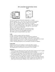
<strong>DT</strong> <strong>2.4GHz</strong> <strong>RECEIVER</strong> <strong>INSTRUCTIONS</strong><strong>Rx35</strong>3-<strong>6v</strong> may be connected with correct orientation to +/- points.Ch1-4 points marked ‘s’, Ch5 and Ch6 are signal connections.The Rx is not insulated so take care to avoid short ci<strong>rc</strong>uits.The PCB is thin so do not bend it or exert great fo<strong>rc</strong>e on it.The receiver will only work with DSM2 transmitters.The Tx/Rx may be switched On/Off in any order.LED:Led On = perfect reception (real-time indicator).Led Off = not perfect (useful for range tests/interference indicator).1 flash = Scanning (~2sec between flashes; wrong model if never stops).2 flash = Brownout/LVC (receiver voltage went too low; check battery/servo load).4 flash = Failsafe (signal lost for >1s eg: Tx switched off before Rx).5 flash = Watchdog (program recovery mechanism; should never happen).FAILSAFE:Outputs are not driven (do nothing) on startup and while scanning.Outputs ‘hold’ on short signal losses (1s).The integrated ESC will cut power to the motor on loss of signal.BINDING:1. The Rx will go into Bind mode 30 seconds after being switched on if no Tx signalis recognised. The led will flash rapidly when ready for binding.2. Switch Tx on in bind mode. The Tx bind button may be released once the Rx ledstops flashing rapidly. The led will stay off for a few seconds and may flash.3. As soon as the led comes on and stays on the Rx is bound and ready to use.4. If led does not come on within 20sec or flashes every 2sec (=scanning), the bindhas failed. Allow several flashes then switch Tx and Rx off, move them closer orfurther apart and start again. Binding is more reliable with no other Tx’s on.OUTPUTS:Ch1-4 will normally be used for servos or an external ESC. Alternatively, Ch3 can beset to produce a 7 channel data stream suitable for multi/quadcopter type models.
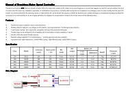
BRUSHED ESC:The Rx has an integrated brushed ESC. It has a conservative 2A rating.The +Positive supply to the motor needs to come direct from the battery. The –Negative supply to the motor is via the FET on the receiver. Reverse moto<strong>rc</strong>onnections to change rotation direction.‘Travel Adjust’ set to 100% both ways normally gives full control over the motor(completely off to fully on). Adjust if necessary. The throttle has to be closed to armthe ESC on startup and after any failsafe event.A 3.0v LVC (Low Voltage Cutoff) is enabled by default but can be disabled. TheESC will rearm after a low voltage event if the throttle is closed briefly. The led willhave a 2-flash if LVC is triggered.PROGRAMMING:Some options can be selected over radio link using the Elevator stick.High/Low selects alternatives and mid-stick then confirms a choice and moves on.'High' means pushing the elevator stick towards the top of the Tx (if not reversed).The led flashes the option currently being set (eg: Option 1 = single-flash 1sec apart).The Rx assigns a value to each option (Low elevator=0; High=option number).The Rx flashes the sum of all options once complete to confirm settings.The Tx changes frequencies every time it is switched on. Programming mode canonly be entered if the Tx is using the same frequencies as were used during the mostrecent bind. So you have to perform a successful new bind (led comes on solid), keepthe Tx on to maintain the same frequencies, and then power cycle the Rx 3 timesmaking sure the led comes on solid after each power cycle. The led should then give arepeating single-flash every 1 second. This is described in steps below:PROGRAMMING PROCEDURE:1. Bind Rx to Tx and led will come on solid.2. Keeping the Tx ON, switch the Rx OFF then ON until it reconnects again (led on).3. Perform step 2 three times until led flashes the first program option (single-flash).4. Use High/Low Elevator to make choices and mid-stick to confirm and move on5. Switch Tx off at any time to save settings.6. The led will then flash the sum of new program settings; switch Rx off when done.7. Switch Rx off before Tx at any time to exit without saving changes.8. To restore defaults, perform steps 1-3 and switch the Tx off (or select Low elevatoron all options). The led will not flash after switching the Tx off because all optionsare reset to 0/Low.
PROGRAM OPTIONS/FLASHES (L=0=Default or not applicable):1. L = Integrated ESC low voltage cutoff ENABLEDH = Integrated ESC low voltage cutoff DISABLED2. L = Sequential PPM DISABLEDH = Sequential PPM ENABLED3. L = Serial output DISABLEDH = Serial output ENABLEDPROGRAMMING EXAMPLES:EXAMPLE 1:Servo outputs and LVC of integrated ESC enabledOption 1-3 LowFlashes after programming 0EXAMPLE 2:Servo outputs and LVC of integrated ESC disabledOption 1 HighOption 2-3 LowFlashes after programming 1EXAMPLE 3:Sequential PPM for quadcopter enabledOption 1 LowOption 2 HighOption 3 LowFlashes after programming 2www.DelTang.co.uk – 3 May 2011 – v3.2.0