
You also want an ePaper? Increase the reach of your titles
YUMPU automatically turns print PDFs into web optimized ePapers that Google loves.
HP-535 Nov. 1998<br />
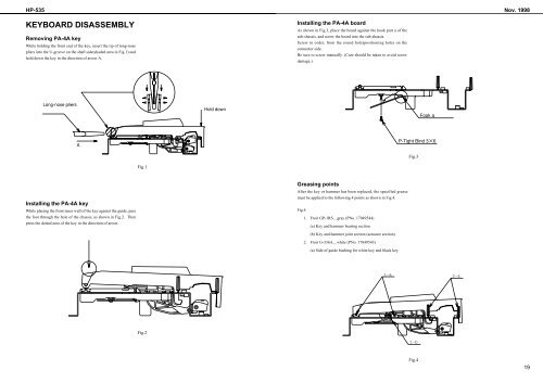
KEYBOARD DISASSEMBLY<br />
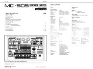
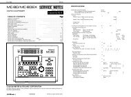
Removing PA-4A key<br />
While holding the front end of the key, insert the tip of long-nose<br />
pliers into the U-groove on the shaft side(shaded area in Fig.1) and<br />
hold down the key in the direction of arrow A.<br />
Installing the PA-4A board<br />
As shown in Fig.3, place the board against the hook part a of the<br />
sub-shassis, and screw the board into the sub-shassis.<br />
Screw in order, from the round hole(positioning hole) on the<br />
connector side.<br />
Be sure to screw manually. (Care should be taken to avoid screw<br />
damage.)<br />
Fig.3<br />
Fig.1<br />
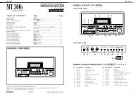
Installing the PA-4A key<br />
While placing the front inner wall of the key against the guide, pass<br />
the foot through the hole of the chassis, as shown in Fig.2. Then<br />
press the dotted area of the key in the direction of arrow.<br />
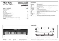
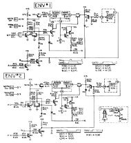
Greasing points<br />
After the key or hammer has been replaced, the specified grease<br />
must be applied to the following 4 points as shown in Fig.4.<br />
Fig.4<br />
1. Froir GP-1RS....gray (PNo. 17049544)<br />
(a) Key and hammer bearing section<br />
(b) Key and hammer joint section (actuator section)<br />
2. Froir G-336A....white (PNo. 17049543)<br />
(a) Side of guide bushing for white key and black key<br />
1-a 2-a<br />
Fig.2<br />
1-b<br />
Fig.4<br />
19