TS-2100 User's Manual - Technologic Systems
TS-2100 User's Manual - Technologic Systems
TS-2100 User's Manual - Technologic Systems

Create successful ePaper yourself
Turn your PDF publications into a flip-book with our unique Google optimized e-Paper software.
<strong>TS</strong>-<strong>2100</strong> User’s <strong>Manual</strong>
<strong>TS</strong>-<strong>2100</strong> User’s <strong>Manual</strong><br />
<strong>Technologic</strong> <strong>Systems</strong><br />
<strong>Technologic</strong> <strong>Systems</strong>, Incorporated<br />
16525 East Laser Drive<br />
Fountain Hills, AZ 85268<br />
480-837-5200<br />
FAX 837-5300<br />
info@embeddedx86.com<br />
http://www.embeddedx86.com/<br />
This revision of the manual is dated<br />
May 21st, 2009<br />
All modifications from previous versions are listed in the appendix.<br />
Copyright © 1998-2000 by <strong>Technologic</strong> <strong>Systems</strong>, Inc. All rights reserved.<br />
ii<br />
05/21/2009
<strong>TS</strong>-<strong>2100</strong> User’s <strong>Manual</strong><br />
<strong>Technologic</strong> <strong>Systems</strong><br />
Limited Warranty<br />
<strong>Technologic</strong> <strong>Systems</strong> warrants this product to be free of defects in material and workmanship for a<br />
period of one year from date of purchase. During this warranty period <strong>Technologic</strong> <strong>Systems</strong> will repair<br />
or replace the defective unit in accordance with the following instructions:<br />
• Contact <strong>Technologic</strong> <strong>Systems</strong> and obtain a Return Material Authorization (RMA) number and a<br />
copy of the RMA form.<br />
• Fill out the RMA form completely and include it and dated proof of purchase with the defective unit<br />
being returned. Clearly print the RMA number on the outside of the package.<br />
This limited warranty does not cover damages resulting from lighting or other power surges, misuse,<br />
abuse, abnormal conditions of operation, or attempts to alter or modify the function of the product.<br />
This warranty is limited to the repair or replacement of the defective unit. In no event shall<br />
<strong>Technologic</strong> <strong>Systems</strong> be liable or responsible for any loss or damages, including but not limited<br />
to any lost profits, incidental or consequential damages, loss of business, or anticipatory profits<br />
arising from the use or inability to use this product.<br />
Repairs made after the expiration of the warranty period are subject to a flat rate repair charge and<br />
the cost of return shipping. Please contact <strong>Technologic</strong> <strong>Systems</strong> to arrange for any repair service.<br />
iii<br />
05/21/2009
<strong>TS</strong>-<strong>2100</strong> User’s <strong>Manual</strong><br />
<strong>Technologic</strong> <strong>Systems</strong><br />
Table Of Contents<br />
LIMITED WARRANTY ........................................................................................................................................ III<br />
1 INTRODUCTION......................................................................................................................................... 5<br />
2 PC COMPATIBILITY ................................................................................................................................... 5<br />
3 POWER ...................................................................................................................................................... 5<br />
4 MEMORY.................................................................................................................................................... 6<br />
4.1 DRAM .................................................................................................................................................................... 6<br />
4.2 Flash...................................................................................................................................................................... 6<br />
4.3 Flash Expansion..................................................................................................................................................... 6<br />
4.4 Battery-Backed SRAM ............................................................................................................................................ 6<br />
5 SERIAL POR<strong>TS</strong> .......................................................................................................................................... 7<br />
5.1 Serial Port Configuration Registers ......................................................................................................................... 7<br />
5.2 Serial Port Hardware .............................................................................................................................................. 7<br />
5.3 RS-485 Support...................................................................................................................................................... 7<br />
5.4 Adding Serial Ports................................................................................................................................................. 8<br />
6 DIGITAL I/O ................................................................................................................................................ 9<br />
6.1 DIO Header ............................................................................................................................................................ 9<br />
6.2 Additional I/O On The JP Header............................................................................................................................ 9<br />
7 REAL TIME CLOCK .................................................................................................................................... 9<br />
8 WATCHDOG TIMER................................................................................................................................... 9<br />
9 LED AND JUMPERS ................................................................................................................................. 10<br />
10 PC/104 BUS EXPANSION......................................................................................................................... 10<br />
11 LOADING, EXECUTING AND DEBUGGING PROGRAMS ....................................................................... 11<br />
11.1 Zmodem Downloads............................................................................................................................................. 11<br />
11.2 Manufacturing Mode............................................................................................................................................. 11<br />
11.3 Integrated BIOS Debugger.................................................................................................................................... 12<br />
12 VIDEO, KEYBOARD, AND CONSOLE REDIRECTION............................................................................. 12<br />
13 FEEDBACK AND UPDATES TO THE MANUAL........................................................................................ 13<br />
APPENDIX A - BOARD DIAGRAM AND DIMENSIONS.................................................................................... 14<br />
APPENDIX B – JP JUMPER BLOCK ................................................................................................................. 14<br />
APPENDIX C – SYSTEM MEMORY MAP ......................................................................................................... 15<br />
APPENDIX D – SYSTEM I/O MAP .................................................................................................................... 15<br />
APPENDIX E - BIOS INTERRUPT FUNCTIONS ............................................................................................... 16<br />
Int 15h / Function B000h - <strong>Technologic</strong> <strong>Systems</strong> BIOS information................................................................................ 16<br />
Int 15h / Function B010h - LED Control ......................................................................................................................... 16<br />
APPENDIX F - DIRECT CONTROL OF THE 386EX DIO PINS ......................................................................... 17<br />
APPENDIX G - USING A 12.5 MHZ BAUD CLOCK ........................................................................................... 18<br />
APPENDIX H - FURTHER REFERENCES ........................................................................................................ 18<br />
APPENDIX I - MANUAL REVISIONS................................................................................................................. 19<br />
iv<br />
05/21/2009
<strong>TS</strong>-<strong>2100</strong> User’s <strong>Manual</strong><br />
<strong>Technologic</strong> <strong>Systems</strong><br />
1 Introduction<br />
The model <strong>TS</strong>-<strong>2100</strong> is a compact, full-featured PC compatible Single Board Computer based on the<br />
386EX processor. If you are coming up from the 8-bit microcontroller world, you will find that this<br />
product provides much more performance and much quicker development since you can now use<br />
standard PC development tools such as Turbo C or Quick Basic. If you have done work in the PC<br />
world in the past, you will find you can now build applications for a very small target that does not<br />
require a keyboard, video, floppy disks, or hard drives.<br />
You can typically write and debug code on a host PC using standard development tools for the PC<br />
platform, then simply copy it to and run it on the <strong>TS</strong>-<strong>2100</strong> without modification. If additional peripherals<br />
are required, the PC/104 expansion bus allows for many standard functions available off-the-shelf. It<br />
is also very simple to create a custom PC/104 daughter board for those special features that<br />
differentiate your product. <strong>Technologic</strong> <strong>Systems</strong> can provide technical support as well as a free<br />
quotation for any custom hardware, software, or BIOS modifications you may require.<br />
This manual is fairly short. This is because for the most part, the <strong>TS</strong>-<strong>2100</strong> is a standard 80386 based<br />
PC compatible computer, and there are hundreds of books about writing software for the PC platform.<br />
The purpose of this manual is documenting where the <strong>TS</strong>-<strong>2100</strong> differs from a standard PC.<br />
2 PC Compatibility<br />
PC compatibility requires much more than just a 386 processor. It requires PC compatible memory<br />
and I/O maps as well as a PC compatible BIOS. The General Software EMBEDDED BIOS offers a<br />
high degree of compatibility with past and present BIOS standards allowing it to run off-the shelf<br />
operating systems and application software.<br />
The EMBEDDED BIOS has been tested with all major versions of DOS, including MS-DOS, DR-DOS,<br />
and Embedded DOS 6-XL; all major versions of OS/2, including MS-OS/2 and IBM OS/2; MS-<br />
Windows 3.1, Windows-95, Windows NT, and NetWare 386.<br />
<strong>Technologic</strong> <strong>Systems</strong> Embedded PCs are compatible with a wide variety of x86 based<br />
operating systems. A partial list OSes currently used with our boards by customers includes:<br />
• TNT Embedded Toolsuite, Phar Lap Software<br />
• RTKernel, On Time Software<br />
• RTEMS, On-Line Applications Research Corporation<br />
• DOS with WATTCP, public domain TCP/IP source code for DOS<br />
3 Power<br />
The <strong>TS</strong>-<strong>2100</strong> requires regulated 5VDC at 475mA (typical). A quick release screw-down terminal block<br />
for the 5V power and power GND connections is provided for easy connection to an external power<br />
supply.<br />
When power is first supplied to the <strong>TS</strong>-<strong>2100</strong>, the board mounted LED is immediately turned on under<br />
hardware control. Once the processor begins execution, the LED is turned off. If the LED does not<br />
turn on at all, the most likely problem is the power supply. Check that the +5V and GND connections<br />
are not reversed. A diode protects the board against damage in such a situation, but it will not run.<br />
Please note that supply voltages over 6VDC may damage the <strong>TS</strong>-<strong>2100</strong>. Be sure to use a regulated<br />
5VDC power supply.<br />
5<br />
05/21/2009
<strong>TS</strong>-<strong>2100</strong> User’s <strong>Manual</strong><br />
<strong>Technologic</strong> <strong>Systems</strong><br />
4 Memory<br />
4.1 DRAM<br />
The <strong>TS</strong>-<strong>2100</strong> has a total of 2 Megabytes of DRAM providing 640 KB of base memory, 1 Megabyte of<br />
extended memory, and 128 KB of shadow RAM for the BIOS and DOS-ROM. This is identical to a<br />
standard PC memory map. The Flash SSD is the exception -- see below for details.<br />
As shipped, the 1 Megabyte of extended memory is used as a RAM disk by the vdisk.sys device<br />
driver. The RAM disk is accessible as drive C: if the DiskOnChip 2000 Flash disk is not installed, drive<br />
D: if it is. The size of the disk can be reduced to provide extended memory for an application (or<br />
simply removed entirely) by editing the CONFIG.SYS file in the root directory of drive A:. Please see<br />
the BIOS/DOS <strong>User's</strong> <strong>Manual</strong> for further information on vdisk.sys.<br />
4.2 Flash<br />
There is a total of 1 MB of Flash memory on the <strong>TS</strong>-<strong>2100</strong>. The top 128 KB of Flash are reserved for<br />
the BIOS and DOS-ROM. During POST, they are copied from Flash into DRAM at addresses E0000h<br />
through FFFFFh for improved performance (a standard technique known as BIOS Shadowing). The<br />
remainder of the Flash memory (896 KB) is used by a SSD (solid state disk) appearing as drive A.<br />
The SSD is fully supported by the BIOS as an INT 13h drive.<br />
The physical Flash memory is accessed by the BIOS through a 64 KB memory mapped window at<br />
addresses D0000h through DFFFFh. If you are installing a PC/104 daughter card that uses memory<br />
mapped I/O, it must not conflict with this address range.<br />
The Flash memory is guaranteed capable of a minimum of 100,000 write/erase cycles. This means<br />
that if you completely erase and rewrite the SSD drive 10 times a day you have over 27 years before<br />
any problems would occur. Reading the SSD produces no wear at all.<br />
4.3 Flash Expansion<br />
If 896 KB of Flash is insufficient for your application, an empty 32-pin socket is available for Flash<br />
expansion using an M-<strong>Systems</strong> DiskOnChip 2000 or DiskOnChip Millennium Flash Drive. This product<br />
is a wonder of miniaturization; it is a complete Flash SSD in a single 32 pin package currently<br />
available in sizes from 4 MB up to 144 MB. The DiskOnChip is available from <strong>Technologic</strong> <strong>Systems</strong><br />
as well as other distributors. It is compatible with DOS as shipped, and drivers for other operating<br />
systems are available.<br />
When using the DiskOnChip, it will simply appear as drive C: The DiskOnChip uses an additional 8 KB<br />
range of CE000h through CFFFFh in memory space. If you are installing a PC/104 daughter card that<br />
uses memory mapped I/O, it must not conflict with this address range if the DiskOnChip is installed. If<br />
it is not installed, there will be no conflict<br />
4.4 Battery-Backed SRAM<br />
The 32-pin socket can also optionally hold 32 KB of battery-backed CMOS SRAM memory. This or the<br />
DiskOnChip may be installed, but not both.<br />
Unlike Flash memory, battery backed SRAM provides non-volatile memory with unlimited write cycles<br />
and no write time degradation. The SRAM uses an additional 32 KB range of C8000h through<br />
CFFFFh. If the SRAM is installed, PC/104 daughter card that uses memory mapped I/O must not<br />
conflict with this address range.<br />
The SRAM can be utilized as a RAM disk (drive C:) by the <strong>TS</strong>RAMDSK.SYS device driver. The device<br />
driver can be added or removed (and the SRAM accessed directly) by editing the associated line in<br />
the CONFIG.SYS file in the root directory of drive A:. Please see the BIOS/DOS <strong>User's</strong> <strong>Manual</strong> for<br />
further information on <strong>TS</strong>RAMDSK.SYS.<br />
6<br />
05/21/2009
<strong>TS</strong>-<strong>2100</strong> User’s <strong>Manual</strong><br />
<strong>Technologic</strong> <strong>Systems</strong><br />
5 Serial Ports<br />
The two PC compatible asynchronous serial ports provide a means to communicate with external<br />
serial devices such as printers, modems, etc. Each is independently configured as a standard PC<br />
COM port which is compatible with the National Semiconductor’s NS16C450. COM1 appears in the<br />
I/O space at 3F8h and uses IRQ4. COM2 is located at 2F8h and uses IRQ3.<br />
The COM ports use a master clock of 1.8519 MHz as compared to a standard clock of 1.8432 MHz.<br />
This results in an error for all baud rates of .0047 (less than ½%). The error is insignificant and this<br />
clock value allows standard baud rate selections -- for example a divisor of 12 yields 9600 baud.<br />
By changing an internal configuration register in the 386EX, the serial clock can be switched to 12.5<br />
MHz (the processor clock divided by 2). This feature allows baud rates higher than 115 kbaud (up to<br />
781 kbaud), as well as low error, non-standard lower baud rates (such as 24 kbaud). See Appendix F<br />
for further information.<br />
The COM ports may also be configured to use a DMA channel, which is handy when very high baud<br />
rates are being used. When enabled, a DMA request is issued any time a serial port’s receive buffer is<br />
full or its transmit buffer is empty. This allows higher speed operation with much lower CPU overhead.<br />
See the Intel 386EX <strong>User's</strong> <strong>Manual</strong> for further details.<br />
5.1 Serial Port Configuration Registers<br />
Because both serial ports are 100% PC compatible, software written for the PC that accesses serial<br />
ports directly or through standard BIOS calls will work without modification on the <strong>TS</strong>-<strong>2100</strong>. The<br />
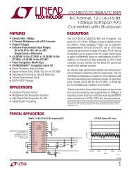
details of the COM port internal registers are available in most PC documentation books or the data<br />
sheet for the National Semiconductor NS16C450 may be consulted.<br />
5.2 Serial Port Hardware<br />
Each serial port has 4 lines buffered: the two data lines<br />
and the C<strong>TS</strong> / R<strong>TS</strong> handshake pair. This is quite sufficient<br />
to interface with the vast majority of serial devices.<br />
The serial lines are routed to 10 pin headers labeled<br />
COM1 and COM2. A serial adapter cable can be plugged<br />
into the header to convert this into a standard DB9 male<br />
connector. The pin out for the 10 pin header and DB9<br />
male connector are listed below. The R<strong>TS</strong> signal also<br />
drives the DTR pin on the serial ports; DTR is always the<br />
same state as R<strong>TS</strong>. In addition, R<strong>TS</strong> is also used to<br />
enable the RS-485 transmitter (see below for more<br />
details).<br />
5.3 RS-485 Support<br />
NC 10 5 GND<br />
NC 9 4 DTR (R<strong>TS</strong>) [out]<br />
[in] C<strong>TS</strong> 8 3 TX data [out]<br />
[out] R<strong>TS</strong> 7 2 RX data [in]<br />
RS-485 TX- / RX- * 6 1 RS-485 TX+ / RX+ *<br />
Figure 1 - Serial Port Header and DB9 Pinout<br />
[signal direction is in brackets]<br />
* RS-485 is optional<br />
PLEASE NOTE: The serial port headers<br />
use a non-standard numbering scheme.<br />
This was done so the header pins would<br />
have the same numbering as the corresponding<br />
DB-9 pin; i.e. pin 8 (C<strong>TS</strong>) on<br />
the header connects to pin 8 on the DB-<br />
9<br />
An option is available to add support to COM1 for half-duplex RS-485. RS-485 drivers allow communications<br />
between multiple nodes up to 4000 feet (1200 meters) via twisted pair cable. Half-duplex<br />
RS-485 requires one twisted pair plus a Ground connection. Full-duplex RS-485 and automatic transmitter<br />
enable for half-duplex are not supported on the <strong>TS</strong>-<strong>2100</strong>. If either of these features is required,<br />
they are supported by the <strong>TS</strong>-2200 EPC.<br />
For half-duplex operation, a single twisted pair is used for transmitting and receiving. The serial port's<br />
R<strong>TS</strong> signal controls the RS-485 transmitter/receiver. When R<strong>TS</strong> is asserted true (bit 1 of the modem<br />
control register = 1), the RS-485 transmitter is enabled and the receiver disabled. When R<strong>TS</strong> is<br />
deasserted the transmitter is tri-stated (disabled) and the receiver is enabled. Since the transmitter<br />
and receiver are never both enabled, the serial port UART does not receive the data transmitted. The<br />
transmitter and receiver share a single pair of signals that are available on pins 1 and 6 of the COM1<br />
10-pin header.<br />
7<br />
05/21/2009
<strong>TS</strong>-<strong>2100</strong> User’s <strong>Manual</strong><br />
<strong>Technologic</strong> <strong>Systems</strong><br />
When the RS-485 option is not installed, TX485EN (JP<br />
header pin 7) is a digital input read at I/O 77h bit 0.<br />
RX485EN# (JP header pin 11) is a digital output controlled<br />
by I/O 76h bit 0.<br />
When the RS-485 option is installed, TX485EN and<br />
RX485EN# control the RS-485 transmitter and receiver<br />
respectively. At system reset, TX485EN is initialized to a<br />
logic ‘0’ (RS-485 transmitter OFF), and RX485EN# is<br />
initialized to a logic ‘1’ (RS-485 receiver OFF).<br />
When a ‘1’ is written to I/O 76h bit 0, RS-485 mode is<br />
enabled and the COM1 R<strong>TS</strong> signal controls both TX485EN<br />
and RX485EN#. When R<strong>TS</strong> is asserted true, TX485EN is<br />
asserted true and RX485EN# is asserted false. This is the<br />
correct state for sending data in RS-485 mode.<br />
When R<strong>TS</strong> is false, TX485EN is false and RX485EN# is<br />
true. This is the correct state for receiving data in RS-485<br />
mode.<br />
When COM1 is using the RS-485 option, jumper JP7<br />
should not be installed. JP7 is only installed when RS-232<br />
is being used on COM1.<br />
It is possible to use COM1 in RS-232 mode even when the<br />
RS-485 option is installed. As long as I/O 76h bit 0 is zero<br />
the RS-485 transmitter and receiver are both disabled. If<br />
JP7 is also installed normal RS-232 operation results.<br />
5.4 Adding Serial Ports<br />
If your project requires more than two serial ports,<br />
additional ports may be added via the PC/104 expansion<br />
bus. <strong>Technologic</strong> <strong>Systems</strong> currently offers a 2 serial / 1<br />
parallel port card, and other manufacturers sell cards with<br />
up to four additional serial ports. Typically these would be<br />
configured as COM3 or COM4 or be assigned other nonstandard<br />
I/O locations. Because DOS only directly<br />
supports four serial ports, any additional ports beyond four<br />
will require software drivers.<br />
RS-485 Quick start procedure:<br />
1. The RS-485 option must be installed<br />
2. Remove JP7 to disable RS-232<br />
operation<br />
3. Attach the RS-485 cable to pins 1 and<br />
6 of the COM1 header.<br />
4. Write a ‘1’ out to I/O address 76h to<br />
enable RS-485 operation<br />
5. Set the COM1 UART serial<br />
parameters (baud rate, data, parity,<br />
and stop bits, interrupts, etc).<br />
6. To transmit data, assert R<strong>TS</strong> and<br />
write the data to the UART<br />
7. To receive data, deassert R<strong>TS</strong> and<br />
read the data from the UART<br />
I/O R / W Bit 0 Description<br />
Address<br />
74h Read Always 0<br />
75h Read SRAM option<br />
0 = Not installed<br />
1 = Option installed<br />
76h Read RS-485 option<br />
0 = Not installed<br />
1 = Option installed<br />
76h Write TX485EN / RS-485 control<br />
0 = disable RS-485<br />
1 = enable RS-485<br />
Or it controls JP header pin<br />
11, if 485 not installed<br />
77h Read Returns status of TX485EN<br />
pin<br />
Table 1 – <strong>TS</strong>-<strong>2100</strong> Control Registers – All<br />
signals are R/W through bit 0 of the address<br />
The PC/104 bus has IRQ3, 4, 5, 6, 7 or 9 available for additional serial ports. If IRQ3 or 4 are to be<br />
used on a PC/104 expansion card, then care must be taken since COM2 and COM1 also use these<br />
IRQs, respectively. For example, if IRQ4 is used for COM3 then either COM1 must be used in a noninterrupt<br />
fashion or only one COM port can have the interrupt enabled at a time. In any case only one<br />
COM should have the Interrupt Enable (Bit 3 of Modem Control Reg.) set at any one time if they share<br />
the same IRQ. This is a standard problem with the PC architecture. A better solution is to simply use<br />
interrupts other than 3 or 4 for additional serial ports.<br />
8<br />
05/21/2009
<strong>TS</strong>-<strong>2100</strong> User’s <strong>Manual</strong><br />
<strong>Technologic</strong> <strong>Systems</strong><br />
6 Digital I/O<br />
6.1 DIO Header<br />
The DIO port provides +5V, GND, and 12 digital I/O lines that may<br />
be used to interface the <strong>TS</strong>-<strong>2100</strong> with a wide range of external<br />
devices. Additional digital I/O is available on the JP header. These<br />
signals are connected directly to the 386EX and several have<br />
multiple functions. For example, DIO pins 6, 11, 12, and 13 are by<br />
default IRQ7, IRQ3, IRQ4, and IRQ5 respectively. By setting configuration<br />
registers in the 386EX, these pins can be individually changed<br />
to general purpose I/O (GPIO) as high-impedance inputs, open-drain<br />
outputs, or complementary outputs. Note that these same signals are also connected directly to the<br />
PC/104 bus; if a pin is configured as GPIO, then the associated IRQ will not be available for PC/104<br />
expansion cards.<br />
DIO pins 7-10 can be configured as a synchronous serial port supporting baud rates to 6.25Mbaud.<br />
These pins are COM2 handshake lines by default that can be used as GPIO.<br />
DIO pins 3, 4, 5, and 14 are always GPIO – they do not have secondary functions.<br />
All digital outputs can source or sink up to 8mA. All digital inputs have standard TTL level thresholds.<br />
For further information on configuration and use of these pins, please See Appendix E.<br />
6.2 Additional I/O On The JP Header<br />
JP header positions JP1, JP2, and JP7 are used to select<br />
operational modes for the <strong>TS</strong>-<strong>2100</strong>. The remaining pins are further<br />
DIO lines available to the user.<br />
Pin 3 is a Digital output that drives the <strong>TS</strong>-<strong>2100</strong> LED. Pins 5,8,9,and<br />
10 are i386EX programmable I/O lines. Pin 6 is a fixed input that can<br />
be read (inverted polarity) at the COM2 Status Reg. (I/O location<br />
2FEh bit 7). Pin 12 is the signal that enables the RS-485 Transmit<br />
driver. If the RS-485 option is not installed, this pin can be read as<br />
input at I/O location 77h bit 0. If RS-485 option is not installed, pin 11 is an output that is determined<br />
by writing to I/O location 76 bit 0. Pin 12 is the i386EX Timer2 output that can be programmed to<br />
generate periodic waveforms.<br />
For further information on configuration and use of these pins, please see Appendix E.<br />
7 Real Time Clock<br />
The Dallas Semiconductor DS12887 is used for the PC compatible battery-backed real-time clock. It is<br />
a completely self-contained module that includes a Motorola 146818 compatible clock chip, the<br />
32.768 kHz crystal, the lithium battery, and 114 bytes of battery-backed CMOS RAM. It is guaranteed<br />
to maintain clock operation for a minimum of 10 years in the absence of power. It is located at the<br />
standard PC I/O addresses of Hex 070 and 071. The top 32 bytes (index 60h through 7Fh) are not<br />
used by the BIOS and are available for user applications.<br />
8 Watchdog Timer<br />
P3.2 14 13 IRQ5 / P3.3<br />
IRQ4 / P3.0 12 11 IRQ3 / P3.1<br />
DTR2 / SRXCLK 10 9 RI2 / SRXD<br />
DSR2 / STXCLK 8 7 R<strong>TS</strong>2 / STXD<br />
IRQ7 / P3.5 6 5 P1.0<br />
P1.5 4 3 P3.6<br />
GND 2 1 5V<br />
Figure 2 - DIO Header Pinout<br />
COM1-RXD 14 13 RS-232 data<br />
12 11 RX485EN*<br />
IRQ6 / P3.4 10 9 P1.3<br />
TIMER2 OUT<br />
R<strong>TS</strong>1 / P1.1 8 7 TX485EN<br />
DCD2 6 5 P1.2<br />
JP2 4 3 Buffered LED<br />
JP1 2 1 GND<br />
Figure 3 - JP Header Pinout<br />
The Intel 386EX contains a 32-bit watchdog timer (WDT) unit that can be used in two different modes<br />
to effect a watchdog supervisory function. In either mode, a system reset is asserted when the WDT<br />
times out preventing a system “hanging” due to a software bug. To prevent a WDT timeout, the<br />
application must periodically “feed” the WDT by writing to specific I/O locations. The 32-bit downcounter<br />
allows timeout values as high as 160 seconds.<br />
9<br />
05/21/2009
<strong>TS</strong>-<strong>2100</strong> User’s <strong>Manual</strong><br />
<strong>Technologic</strong> <strong>Systems</strong><br />
The general-purpose timer mode is more flexible in that the timeout values can be changed<br />
dynamically and the timer can be turned on and off under software control. The disadvantage of this<br />
mode is that it doesn’t provide 100% protection because a bug could turn off the timer during a crash<br />
and the system would hang.<br />
The software secure watchdog mode utilizes a “lockout sequence” to set a WDTEN bit in the watchdog<br />
status register. Once this bit is set, only a system reset can clear this bit. When WDTEN is set, it<br />
is not possible to change the WDT timeout value or to turn off the WDT. This provides a high level of<br />
assurance against errant software causing a system to hang.<br />
For details see the Intel 386EX User <strong>Manual</strong>.<br />
9 LED and Jumpers<br />
The <strong>TS</strong>-<strong>2100</strong> has a red LED available for user software. Example uses include diagnostics, status<br />
messages, and simple output. This signal is also available as a digital output on the JP header.<br />
When power is first supplied to the <strong>TS</strong>-<strong>2100</strong>, the board mounted LED is immediately turned on under<br />
hardware control. Once the processor begins execution, the LED is turned off, then flashed on and off<br />
again briefly. If the LED does not turn on at all, the most likely problem is the power supply. Check<br />
that the +5V and GND connections are not reversed. A diode protects the board against damage in<br />
such a situation, but it will not run.<br />
BIOS interrupt functions are used to interface software with the LED and option jumpers. Please see<br />
Appendix C for further details and the utility disk for example code.<br />
10 PC/104 Bus Expansion<br />
The PC/104 is a compact implementation of the PC/AT ISA bus ideal<br />
for embedded applications. Designers benefit from using an alreadydeveloped<br />
standard, rather than<br />
Pin #<br />
A1<br />
B5<br />
B6<br />
B7<br />
B8<br />
B9<br />
Signal Name<br />
IOCHCHK#<br />
-5V<br />
DRQ2<br />
-12V<br />
ENDXFR#<br />
+12V<br />
creating their own. Further, the<br />
presence of a compact form-factor<br />
PC compatible standard has<br />
encouraged the development of a<br />
broad array of off-the-shelf<br />
products, allowing a very quick time<br />
to market for new products.<br />
B15 DACK3# ‡<br />
B16 DRQ3 ‡<br />
B17<br />
B18<br />
B19<br />
B26<br />
B27<br />
DACK1#<br />
DRQ1<br />
REFRESH#<br />
DACK2#<br />
TC<br />
Table 3 - Unsupported PC/104 Signals<br />
‡ PC/104 expansion cards must not<br />
connect to these pins.<br />
The electrical specification for the<br />
PC/104 expansion bus is identical<br />
to the PC ISA bus. The mechanical<br />
specification allows for the very<br />
compact implementation of the ISA<br />
bus tailor made for embedded<br />
systems. The full PC/104<br />
specification is available from the<br />
IEEE Standards Office under #<br />
IEEE P996.1 (see Appendix G for<br />
further information). Basically, this bus allows multiple daughter<br />
boards in a 3.6 inch by 3.8 inch form factor to be added in a selfstacking<br />
bus. Since the electrical specs are identical (except for drive<br />
levels) to a standard PC ISA bus, standard peripherals such as COM<br />
ports, Ethernet, video, LCD drivers, and Flash drives may be easily<br />
added using standard drivers.<br />
The <strong>TS</strong>-<strong>2100</strong> implements a sub-set of the 8-bit version of the PC/104<br />
bus. We have found this allows the support of the vast majority of<br />
10<br />
Pin #<br />
A2 - A9<br />
A10<br />
A11<br />
A12 - A31<br />
A32<br />
B1<br />
B2<br />
Signal Name<br />
D7 through D0<br />
IOCHRDY<br />
EN<br />
A19 through A0<br />
GND<br />
GND<br />
B3 +5V<br />
B4<br />
B11<br />
B12<br />
B13<br />
B14<br />
B20<br />
RESETDRV<br />
IRQ9<br />
SMEMW#<br />
SMEMR#<br />
IOW#<br />
IOR#<br />
B21 IRQ7 †<br />
B22 IRQ6 †<br />
B23 IRQ5 †<br />
B24 IRQ4 †<br />
B25 IRQ3 †<br />
B28<br />
SYSCLK (8.33 MHz)<br />
BALE<br />
B29 +5V<br />
B30<br />
B31<br />
B32<br />
OSC<br />
GND<br />
GND<br />
Table 2 - Supported PC/104 Signals<br />
† These signals are also<br />
connected to the DIO port.<br />
05/21/2009
<strong>TS</strong>-<strong>2100</strong> User’s <strong>Manual</strong><br />
<strong>Technologic</strong> <strong>Systems</strong><br />
PC/104 boards including all of the above mentioned examples. The one feature missing is DMA,<br />
which few PC/104 boards use.<br />
See Figure 4 (Appendix A) for information on PC/104 pin numbering<br />
11 Loading, Executing and Debugging Programs<br />
Two methods are available for transferring files between a desktop PC and your <strong>TS</strong>-<strong>2100</strong>: Zmodem<br />
downloads, and Manufacturing Mode. Full descriptions of each are detailed below.<br />
To make your program automatically execute at power up, just edit the AUTOEXEC.BAT file on the<br />
Flash SSD drive and replace the name of the factory test program (EPC-DIAG.EXE) with yours.<br />
11.1 Zmodem Downloads<br />
Using the Zmodem protocol to send files to and from the <strong>TS</strong>-<strong>2100</strong> is simple and straightforward. The<br />
only requirement is a terminal emulation program that supports Zmodem, and virtually all do. If you are<br />
using Windows 9X for your development work, the HyperTerminal accessory works well.<br />
To download a file to the <strong>TS</strong>-<strong>2100</strong> from your host PC, execute DL.BAT at the DOS command line on<br />
the <strong>TS</strong>-<strong>2100</strong> (while using console-redirection from within your terminal emulator) and begin the<br />
transfer with your terminal emulator. In HyperTerminal, this is 'Send File...' from the 'Transfer' menu.<br />
To upload a file from the <strong>TS</strong>-<strong>2100</strong> to your host PC, execute UL.BAT at the DOS<br />
command line on the <strong>TS</strong>-<strong>2100</strong> and start the transfer in your terminal emulator. Many emulators,<br />
HyperTerminal among them, will automatically begin the transfer themselves.<br />
Occasionally there may be errors in transmission due to background solid state disk operations. This<br />
is not a problem -- Zmodem uses very accurate CRC checks to detect errors and simply resends bad<br />
data. Once the file transfer is complete the file is completely error free.<br />
Please note that the utility used to perform Zmodem file transfers on the <strong>TS</strong>-<strong>2100</strong> side is called DSZ,<br />
produced by Omen Technologies. DSZ is shareware -- it is not free. If you decide to use it, you are<br />
legally obligated to pay Omen Technologies. Currently the cost is $20. Further info is available in the<br />
DSZ zip file located on the utility disk, and contact info for Omen Technologies is in Appendix G.<br />
11.2 Manufacturing Mode<br />
The <strong>TS</strong>-<strong>2100</strong> has a special feature called 'Manufacturing Mode' which makes the on-board Flash SSD<br />
appear as just another drive on your desktop computer using a DOS device driver and a serial cable.<br />
First, connect a null modem cable between COM2 on the <strong>TS</strong>-<strong>2100</strong> and COM1 or COM2 of your<br />
desktop computer. Next, the <strong>TS</strong>-<strong>2100</strong> must be placed in Manufacturing Mode. To do so, install jumper<br />
JP1 and power cycle the unit. Manufacturing Mode will automatically start once the POST routines<br />
have been executed. At this point, the <strong>TS</strong>-<strong>2100</strong> will simply sit and wait for serial packets to arrive from<br />
a host.<br />
Now install the Manufacturing Mode driver on your desktop computer. To do so, simply copy the<br />
MFGDRV.SYS device driver from the utility disk to anywhere on your desktop machine's hard drive.<br />
Then insert the following line in your CONFIG.SYS file and reboot:<br />
DEVICE=\MFGDRV.SYS /UNIT=0 /BAUD=38K /PORT=COMX<br />
Where is the full path to the location where you copied the MFGDRV.SYS driver, and X is the<br />
port on your host PC that the null modem cable is connected to (1 or 2).<br />
The Flash SSD drive should now appear on the next free drive letter on your desktop computer<br />
(usually the D: or E: drive). Simply copy your program onto the drive, and that's it!<br />
You can create directories, edit files, and even execute programs on your desktop computer over the<br />
Manufacturing Mode link just the way you would with a regular disk drive, just a bit more slowly.<br />
11<br />
05/21/2009
<strong>TS</strong>-<strong>2100</strong> User’s <strong>Manual</strong><br />
<strong>Technologic</strong> <strong>Systems</strong><br />
When you are finished, turn off the <strong>TS</strong>-<strong>2100</strong>, remove the jumper, and turn it back on. Your program<br />
will now execute every time the <strong>TS</strong>-<strong>2100</strong> is turned on.<br />
While Manufacturing Mode is in operation, the board LED provides feedback. While idle, the LED will<br />
cycle on and off at approximately 1/2 Hertz. While data is being transferred, it will cycle much more<br />
rapidly (anywhere from 5 to 1000 Hertz)<br />
NOTE: The Manufacturing Mode driver currently does not work correctly with Windows 9X (95/98).<br />
Please use the Zmodem method if you are using Windows 9X.<br />
11.3 Integrated BIOS Debugger<br />
To provide simple, direct access to the <strong>TS</strong>-<strong>2100</strong> hardware, the system BIOS has an integrated<br />
debugger that can perform standard low-level debugger functions. The debugger allows you to<br />
perform operations such as disassemble code, display and alter the contents of memory, write to and<br />
read from I/O ports, and single-step through or breakpoint code. The debugger is not intended for use<br />
as the only debugging tool for applications, but it can be a real lifesaver when you need interactive,<br />
direct access to hardware.<br />
The BIOS debugger can be entered by any of several methods:<br />
• The debugger hooks the CPU exception vectors in case a divide by zero occurs, an invalid opcode<br />
is executed, or an INT 3 instruction is executed, for example. By placing an INT 3 instruction in<br />
your application code the debugger will automatically be invoked. To resume, type the 'G'<br />
command to "GO", or continue on with the rest of initialization.<br />
• From DOS-ROM by typing ‘INT3’ at the command prompt. If the full command.com interpreter is<br />
running, this is an internal command. If only mini-command.com is running, this will execute a<br />
small utility that simply contains an ‘INT 3’ instruction.<br />
• From the BIOS Setup main menu (started by typing ‘ctrl-C’ during the BIOS POST), the ENTER<br />
SYSTEM BIOS DEBUGGER selection will enter the debugger. After use, typing the ‘G’ (go)<br />
command will return to the SETUP screens.<br />
• As a boot action, as a last-ditch effort if the operating system cannot be booted from the<br />
appropriate drives or out of ROM.<br />
A complete discussion of debugger commands is available in the Integrated BIOS Debugger<br />
Reference <strong>Manual</strong>, included on the <strong>TS</strong>-<strong>2100</strong> Utility Disk and also available from the <strong>Technologic</strong><br />
<strong>Systems</strong> web site. Entering ‘?’ will list all available commands, and a ‘g’ (go) will return execution to<br />
the point where the debugger was called.<br />
12 Video, Keyboard, and Console Redirection<br />
The <strong>TS</strong>-<strong>2100</strong> has no video controller or keyboard interface. This was done to keep the board size<br />
small and the cost low. For applications that require it, a PC/104 video board can be added to the<br />
system easily. This could be a VGA controller, graphic LCD interface, or a custom board of your own<br />
design.<br />
Without a video board in the system, the <strong>TS</strong>-<strong>2100</strong> redirects all console activity to the COM2 serial<br />
port. Simply connect an ANSI terminal (or emulator) to COM2 with a null modem cable, using serial<br />
parameters of 9600 baud, 8 data bits, no parity, 1 stop bit, and make sure jumper JP2 is installed. All<br />
text information that would normally be displayed on a video screen is now displayed in your terminal<br />
window, and any serial data sent to the <strong>TS</strong>-<strong>2100</strong> is seen as standard keyboard input by programs.<br />
Please note that the console redirection support is limited by the fact that there is no actual video or<br />
keyboard hardware on the <strong>TS</strong>-<strong>2100</strong>. Programs must use the standard BIOS routines for display and<br />
keyboard input, which are rerouted to the serial port. Any program that accesses the video or keyboard<br />
hardware directly will not work. Keyboard redirection is limited simply because most of the<br />
extended keys on the keyboard (function keys and Alt key in particular) are not sent by the terminal<br />
12<br />
05/21/2009
<strong>TS</strong>-<strong>2100</strong> User’s <strong>Manual</strong><br />
<strong>Technologic</strong> <strong>Systems</strong><br />
emulator. For these reasons, the console redirection feature is meant more for system development,<br />
testing, and field repair, rather than as the primary user interface for a finished product.<br />
If your application uses COM2, removing the jumper JP2 easily disables console redirection.<br />
If you wish to use a different serial port and / or baud rate for the console, the CONSOLE.EXE utility<br />
allows these modifications to be made. Please see the appropriate application notes for further<br />
details, available on the utility disk or from the <strong>Technologic</strong> <strong>Systems</strong> web site.<br />
If a video board is installed on the PC/104 bus, the video BIOS on the graphics card will automatically<br />
replace the standard video routines (INT10h), disabling both the LCD display and the display<br />
redirection (keyboard redirection will continue). If the console redirection jumper JP2 is also removed,<br />
the keyboard redirection is disabled as well.<br />
13 Feedback and Updates to the <strong>Manual</strong><br />
To help our customers make the most of our products, we are continually making additional and<br />
updated resources available on the <strong>Technologic</strong> <strong>Systems</strong> web site. These include manuals,<br />
application notes, programming examples, and updated software and firmware. Check in periodically<br />
to see what's new!<br />
When we are prioritizing work on these updated resources, feedback from customers (and<br />
prospective customers) is the number one influence. If you have questions, comments, or concerns<br />
about your <strong>TS</strong>-<strong>2100</strong> Embedded PC, please let us know. Details for contacting us are listed in the front<br />
of this manual.<br />
13<br />
05/21/2009
<strong>TS</strong>-<strong>2100</strong> User’s <strong>Manual</strong><br />
<strong>Technologic</strong> <strong>Systems</strong><br />
Appendix A - Board Diagram and Dimensions<br />
A1<br />
B1<br />
Power<br />
+5V<br />
GND<br />
JP HEADER<br />
PC/104<br />
COM1<br />
COM2<br />
32 Pin Socket<br />
DIO PORT<br />
3.550"<br />
3.350"<br />
0.200"<br />
0.300"<br />
3.200"<br />
A32 B32<br />
Figure 4 - Board Diagram<br />
0.200"<br />
3.575"<br />
3.775"<br />
Figure 5 - Board Dimensions (standard PC/104 8-bit<br />
module dimensions)<br />
Appendix B – JP Jumper Block<br />
COM1-RXD 14 13 RS-232 data<br />
12 11 RX485EN*<br />
IRQ6 / P3.4 10 9 P1.3<br />
TIMER2 OUT<br />
R<strong>TS</strong>1 / P1.1 8 7 TX485EN<br />
DCD2 6 5 P1.2<br />
JP2 4 3 Buffered LED<br />
JP1 2 1 GND<br />
Figure 6 - JP Header Pinout<br />
Table 4 lists all option jumpers and their functions.<br />
These jumpers are clearly labeled in the lower right<br />
corner of the board (see Figure 4).<br />
Jumper Installed on Pins Function<br />
JP1 1 – 2 Manufacturing Mode<br />
JP2 3 – 4 Console Redirection<br />
JP7 13 - 14 Enable COM1 RS-232<br />
Table 4 - Jumper Listing<br />
14<br />
05/21/2009
<strong>TS</strong>-<strong>2100</strong> User’s <strong>Manual</strong><br />
Appendix C – System Memory Map<br />
Resource<br />
Starting Address<br />
hex<br />
decimal<br />
<strong>Technologic</strong> <strong>Systems</strong><br />
Size<br />
Extended Memory (RAM)<br />
1M<br />
100000h<br />
1024k<br />
BIOS<br />
(Shadow RAM) F0000h 960k<br />
64k<br />
DOS / BIOS Extension<br />
(Shadow RAM) E0000h 896k<br />
64k<br />
Solid-state disk drive window<br />
(Flash RAM) D0000h 832k<br />
64k<br />
PC/104 or DiskOnChip CE000h 824k 8k<br />
PC/104 or Battery-Backed SRAM C8000h 800k 24k<br />
PC/104<br />
(typically video BIOS) C0000h 768k<br />
32k<br />
PC/104<br />
(typically video memory)<br />
A0000h<br />
640k<br />
128k<br />
Lower Memory<br />
(RAM)<br />
00000h 00000<br />
Figure 7 – <strong>TS</strong>-<strong>2100</strong> Memory Map (Not to scale)<br />
640k<br />
Appendix D – System I/O Map<br />
The following table lists the I/O addresses used by the system. All other I/O locations from 100h<br />
through 3F7h are available on the PC/104 expansion bus.<br />
Hex Address Resource<br />
F000h - FFFFh<br />
400h – EFFFh<br />
3F8h – 3FFh<br />
2F8h – 2FFh<br />
80h – FFh<br />
074h – 077h<br />
070h – 071h<br />
000h – 06Fh<br />
Internal 386EX Registers<br />
PC/104 Bus<br />
(Not recommended for use)<br />
COM1<br />
COM2<br />
Internal 386EX peripherals<br />
Board configuration registers<br />
RTC and CMOS memory<br />
Internal 386EX peripherals<br />
Table 5 – <strong>TS</strong>-<strong>2100</strong> I/O Map<br />
I/O R / W Bit 0 Description<br />
Address<br />
74h Read Always 0<br />
75h Read SRAM option<br />
0 = Not installed<br />
1 = Option installed<br />
76h Read RS-485 option<br />
0 = Not installed<br />
1 = Option installed<br />
76h Write TX485EN / RS-485 control<br />
0 = disable RS-485<br />
1 = enable RS-485<br />
Or it controls JP header pin 11,<br />
if 485 not installed<br />
77h Read Returns status of TX485EN pin<br />
Table 6 – <strong>TS</strong>-<strong>2100</strong> Control Registers – All signals<br />
are R/W through bit 0 of the address<br />
15<br />
05/21/2009
<strong>TS</strong>-<strong>2100</strong> User’s <strong>Manual</strong><br />
<strong>Technologic</strong> <strong>Systems</strong><br />
Appendix E - BIOS Interrupt Functions<br />
We have extended the standard BIOS interrupts with several functions that simplify interfacing with<br />
the <strong>TS</strong>-<strong>2100</strong> hardware.<br />
Many books are available with detailed information on using interrupts with just about any language.<br />
Example code is also available on the utility disk.<br />
Int 15h / Function B000h - <strong>Technologic</strong> <strong>Systems</strong> BIOS information<br />
This function is mostly for our own internal use, but may be useful for user programs as well. For<br />
example, your program could have debugging code that executes on your desktop machine, but does<br />
not when the program is executing on the <strong>TS</strong>-<strong>2100</strong>.<br />
ENTRY:<br />
EXIT:<br />
AX = B000h<br />
CY = 0 (carry flag)<br />
AH = 0<br />
AL = SP_VERSION<br />
For standard versions of the BIOS, this is 0. An 'SP number' is assigned when custom<br />
modifications are made to the BIOS for a client, and it is returned in this register. Contact<br />
us for further information.<br />
BH = BIOS Version, Major Number.<br />
E.g. If the current BIOS version is 1.25, the register will contain 01h.<br />
BL = BIOS Version, Minor Number.<br />
E.g. If the current BIOS version is 1.25, the register will contain 19h (19h = 25 decimal).<br />
CH = Base Flash Memory Size / 512kB<br />
The <strong>TS</strong>-<strong>2100</strong> is available with 1024kB of base Flash memory standard. This would be<br />
returned as 02h.<br />
CL = 15h<br />
This is the hardware model number (15h = 21 decimal).<br />
DX = '<strong>TS</strong>' (5452h)<br />
Int 15h / Function B010h - LED Control<br />
This function is used to turn the board LED on and off. You can also invert the LED, i.e. if the LED is<br />
off, it will be turned on, and if it is on it will be turned off.<br />
ENTRY:<br />
EXIT:<br />
AX = B010h<br />
BH = 00 - LED off.<br />
01 - LED on.<br />
81 - LED invert.<br />
CY = 0 (carry flag)<br />
AH = 0<br />
16<br />
05/21/2009
<strong>TS</strong>-<strong>2100</strong> User’s <strong>Manual</strong><br />
<strong>Technologic</strong> <strong>Systems</strong><br />
Appendix F - Direct Control of the 386EX DIO Pins<br />
The Intel386 EX processor has three 8-bit bi-directional I/O ports, all of which are functionally identical<br />
(Figure 16-1). Each port has three control registers and a status register. All three ports share pins<br />
with internal peripherals. Several of these pins are routed to the DIO ports. If your design does not<br />
require a pin’s peripheral function, you can configure that pin for use as an I/O port. For example, if<br />
you don’t need IRQ6 for PC/104, you can use the associated pin (386EX P3.4) as a DIO on JP<br />
header pin 10. Each pin can operate either in I/O mode or in peripheral mode. In I/O mode, a pin has<br />
three possible configurations:<br />
• high-impedance input<br />
• open-drain output (requires an external pull-up resistor)<br />
• complementary output<br />
In I/O mode, register bits control the direction (input or output) of each pin and the value of each<br />
output pin. In peripheral mode, the internal peripheral controls the operation (input or output) of the<br />
pin.<br />
Each port has three control registers and a status register associated with it (). The control registers<br />
(PnCFG, PnDIR, and PnLTC) can be both read and written. The status register (PnPIN) can only be<br />
read. All four registers reside in I/O address space.<br />
Register I/O Address Description<br />
P1CFG<br />
P3CFG<br />
(read/write)<br />
P1DIR<br />
P3DIR<br />
(read/write)<br />
P1LTC<br />
P3LTC<br />
(read/write)<br />
P1PIN<br />
P3PIN<br />
(read only)<br />
0F820h<br />
0F824h<br />
0F864h<br />
0F874h<br />
0F862h<br />
0F872h<br />
0F860h<br />
0F870h<br />
Port n Mode Configuration:<br />
Each bit controls the mode of the associated pin.<br />
0 = Selects I/O mode.<br />
1 = Selects peripheral mode.<br />
Port n Direction:<br />
Each bit controls the direction of a pin that is in I/O mode. If a pin is in<br />
peripheral mode, this value is ignored.<br />
0 = Configures a pin as a complementary output.<br />
1 = Configures a pin as either an input or an open-drain output.<br />
Port n Data Latch:<br />
Each bit contains data to be driven on to an output pin that is in I/O mode.<br />
Write the desired pin state value to this register. If a pin is in peripheral<br />
mode, this value is ignored.<br />
Writing a value to a PL bit causes that value to be driven onto the<br />
corresponding pin.<br />
For a complementary output, write the desired pin value to its PL bit. This<br />
value is actively driven high or low onto the pin.<br />
For an open-drain output, a zero results in a actively driven low on the pin,<br />
a one results in a high-impedance (input) state at the pin.<br />
To configure a pin as an input, write a one to the corresponding PL bit. A<br />
one results in a high-impedance state at the pin, allowing external hardware<br />
to drive it.<br />
Reading this register returns the value in the register – not the actual pin<br />
state.<br />
Port n Pin State:<br />
Each bit of this read-only register reflects the state of the associated pin.<br />
Reading this register returns the current pin state value, regardless of the<br />
pin’s mode and direction.<br />
Table 7 – 386EX I/O Port Registers<br />
17<br />
05/21/2009
<strong>TS</strong>-<strong>2100</strong> User’s <strong>Manual</strong><br />
<strong>Technologic</strong> <strong>Systems</strong><br />
In the default configuration, P1.5, P1.0 and P3.6 are all initialized as inputs, while P3.0, P3.1, and<br />
P3.3 are initialized as "peripherals" (IRQ4, IRQ3, and IRQ5)<br />
Warning: When changing these registers, always use read/modify/write procedures so that<br />
other port pins (used by on-board peripherals) are not affected.<br />
For example, let's say you want to use 386EX Port 3.1 (DIO pin 11) as an output rather than IRQ3<br />
(the default configuration).<br />
1. Read P3CFG (I/O F824h), AND it with 0FDh, write it back to F824h. (changes from peripheral<br />
to I/O pin)<br />
2. Read P3DIR (I/O F874h), AND it with 0FDh, write it back to F874h. (this made it a<br />
complementary output)<br />
3. To set this pin to a "1", Read P3LTC (I/O F872h), OR it with 02h, write it back.<br />
Note: Because the serial ports are internal to the 386EX, COM1 and COM2 can still use IRQ4 and<br />
IRQ3 even when the associated pins P3.1 and P3.0 are configured as DIO pins DIO1.11 and DIO1.12<br />
– the interrupts are simply no longer available on the PC/104 bus.<br />
Appendix G - Using A 12.5 MHz Baud Clock<br />
Each serial port baud rate generator clock can be independently switched between either the<br />
standard 1.85 MHz clock or a 12.5 MHz clock (the internal processor clock divided by 2).<br />
Changing the clock to 12.5 MHz allows baud rates higher than 115 kbaud (up to 781 kbaud), as well<br />
as low error, non-standard lower baud rates (such as 24 kbaud).<br />
The baud rate clock is controlled by I/O location 0F836h:<br />
Bit 0 controls COM1.<br />
Bit 1 controls COM2.<br />
Setting a bit to 0 uses the standard 1.85 MHz clock, and setting a bit to 1 uses the 12.5 MHz<br />
processor clock. NOTE: You must not modify the other bits of this register. You must use a readmodify-write<br />
procedure to change these bits. The following example in assembly illustrates this:<br />
MOV DX, 0F836 ; load the I/O address<br />
IN AL, DX ; read the configuration register<br />
OR AL, 00000001b ; switch COM1 to the 12.5 MHz clock<br />
OUT DX, AL ; write the register<br />
Appendix H - Further References<br />
<strong>Technologic</strong> <strong>Systems</strong> Web Site<br />
http://www.embeddedx86.com/<br />
Dallas Semiconductor DS12887 Data Sheet<br />
Intel 386EX <strong>User's</strong> Guide<br />
http://developer.intel.com/design/intarch/manuals/272485.htm<br />
Maxim Integrated Products<br />
http://www.maxim-ic.com/<br />
National Semiconductor NS16C450 Data Sheet<br />
Omen Technologies<br />
http://www.omen.com/<br />
PC/104 Consortium Web Site<br />
http://www.pc104.org/<br />
18<br />
05/21/2009
<strong>TS</strong>-<strong>2100</strong> User’s <strong>Manual</strong><br />
<strong>Technologic</strong> <strong>Systems</strong><br />
Appendix I - <strong>Manual</strong> Revisions<br />
05/21/09 Updated mailing address<br />
06/04/01 • Updated board dimensions in Appendix A<br />
11/6/00 • Updated System I/O Map<br />
• Updated URL to Intel 386EX <strong>User's</strong> Guide<br />
07/22/99 • Added section 11.3 & Appendix F<br />
07/21/99 • Added Appendix D<br />
• Fixed minor errors<br />
• More info on JP jumper block<br />
04/30/99 • Added Figure 5 Board Dimensions<br />
• Added PC/104 pin-out numbering to Figure 4.<br />
• More info on JP jumper block<br />
• Added system memory and I/O maps<br />
• More info on RS-485<br />
• Fixed several minor typos<br />
04/27/99 • New manual.<br />
19<br />
05/21/2009