TS-9500 Manual - Technologic Systems
TS-9500 Manual - Technologic Systems
TS-9500 Manual - Technologic Systems

You also want an ePaper? Increase the reach of your titles
YUMPU automatically turns print PDFs into web optimized ePapers that Google loves.
<strong>TS</strong>-<strong>9500</strong> <strong>Manual</strong>
<strong>Technologic</strong> <strong>Systems</strong>, Incorporated<br />
16525 East Laser Drive<br />
Fountain Hills, AZ 85268<br />
480-837-5200<br />
FAX 837-5300<br />
info@embeddedx86.com<br />
http://www.embeddedx86.com/<br />
This revision of the manual is dated<br />
July 9, 2009<br />
All modifications from previous versions are listed in the appendix.<br />
Copyright © 1998-2009 by <strong>Technologic</strong> <strong>Systems</strong>, Inc. All rights reserved.
Limited Warranty<br />
<strong>Technologic</strong> <strong>Systems</strong> warrants this product to be free of defects in material and<br />
workmanship for a period of one year from date of purchase. During this warranty period<br />
<strong>Technologic</strong> <strong>Systems</strong> will repair or replace the defective unit in accordance with the<br />
following instructions:<br />
• Contact <strong>Technologic</strong> <strong>Systems</strong> and obtain a Return Material Authorization (RMA)<br />
number and a copy of the RMA form.<br />
• Fill out the RMA form completely and include it and dated proof of purchase with<br />
the defective unit being returned. Clearly print the RMA number on the outside of<br />
the package.<br />
This limited warranty does not cover damages resulting from lighting or other power<br />
surges, misuse, abuse, abnormal conditions of operation, or attempts to alter or modify<br />
the function of the product.<br />
This warranty is limited to the repair or replacement of the defective unit. In no<br />
event shall <strong>Technologic</strong> <strong>Systems</strong> be liable or responsible for any loss or damages,<br />
including but not limited to any lost profits, incidental or consequential damages,<br />
loss of business, or anticipatory profits arising from the use or inability to use this<br />
product.<br />
Repairs made after the expiration of the warranty period are subject to a flat rate repair<br />
charge and the cost of return shipping. Please contact <strong>Technologic</strong> <strong>Systems</strong> to arrange<br />
for any repair service.
Table of Contents<br />
Limited Warranty............................................................................................................................................................. 3<br />
1. Introduction.............................................................................................................................................................. 5<br />
2. PC/104 Bus Interface ............................................................................................................................................. 5<br />
3. VGA Video, Keyboard, and Mouse.................................................................................................................... 5<br />
4. Compact Flash......................................................................................................................................................... 6<br />
5. Using the SanDisk USB Compact Flash Reader ............................................................................................... 6<br />
6. Using LCD, Matrix Keypad with <strong>TS</strong>-<strong>9500</strong>........................................................................................................ 6<br />
7. Booting from <strong>TS</strong>-<strong>9500</strong> ........................................................................................................................................... 7<br />
8. Using the <strong>TS</strong>-<strong>9500</strong> with a <strong>TS</strong>-3100..................................................................................................................... 7<br />
9. Using the <strong>TS</strong>-<strong>9500</strong> with a <strong>TS</strong>-2100, <strong>TS</strong>-2200, <strong>TS</strong>-2800 ................................................................................. 7<br />
10. Jumper and Dip Switch Settings...................................................................................................................... 8<br />
Appendix A I/O Memory Map ...................................................................................................................................... 9<br />
Appendix B <strong>Manual</strong> Revisions...................................................................................................................................... 9
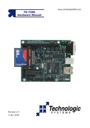
1. Introduction<br />
The <strong>Technologic</strong> <strong>Systems</strong> <strong>TS</strong>-<strong>9500</strong> is a valuable tool when developing for any<br />
<strong>Technologic</strong> <strong>Systems</strong> Single Board Computer (SBC). It features a Compact Flash<br />
interface, standard VGA video connector, and standard connectors for a PS/2 Keyboard<br />
and Mouse. The <strong>TS</strong>-<strong>9500</strong> daughter board allow s for a developer to write source code,<br />
compile, run, and debug right on the target SBC using a typical PC compatible<br />
development suite (such as Borland's Turbo C). By simply moving your development<br />
tools onto the Compact Flash card, and plugging in monitor and keyboard, one can<br />
develop and debug directly on the target platform.<br />
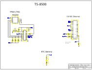
2. PC/104 Bus Interface<br />
The <strong>TS</strong>-<strong>9500</strong> features a 16-bit PC/104 Bus that is compatible with <strong>Technologic</strong> <strong>Systems</strong><br />
3000 and 5000 series of SBC. These products use a standard PC/104 bus except that<br />
pin A1 is used for the IRQ1 function (instead of the NMI function). The <strong>TS</strong>-<strong>9500</strong><br />
keyboard controller uses this interrupt for keyboard input (as per a standard PC). This is<br />
a non-standard usage for this PC/104 Bus pin, but there is little chance of a conflict,<br />
since the standard function of this pin is “Parity Error” for extended memory daughter<br />
boards, which should never be needed with our products.<br />
I/O locations 198h through 019Fh are used by the <strong>TS</strong>-<strong>9500</strong>. When installing other<br />
PC/104 daughter boards, the user must ensure that there is no conflict with these I/O<br />
locations.<br />
Although the <strong>TS</strong>-<strong>9500</strong> uses the full 16-bit bus, it can support SBC products with only an<br />
8-bit bus (such as the <strong>TS</strong>-3100). All resources except the Compact Flash can function<br />
with a restricted 8-bit bus. When using an SBC with an 8-bit bus, the Compact Flash will<br />
be non-functional.<br />
3. VGA Video, Keyboard, and Mouse<br />
No special cables are needed to use the VGA, keyboard, and mouse interfaces. Simply<br />
plug in your monitor into the <strong>TS</strong>-<strong>9500</strong> VGA connector as you would for any other typical<br />
PC computer. A PS/2 keyboard plugs into the connector labeled KeyBoard (farthest<br />
from the VGA connector). A PS/2 mouse plugs into the connector between the VGA<br />
connector and the Keyboard connector. The <strong>TS</strong>-<strong>9500</strong> uses a Chips and Technology<br />
65545 chip for the VGA video generation and it uses an Intel 82C42PC chip with<br />
Phoenix Technologies Ltd. firmware for the keyboard and mouse controller.<br />
The mouse interface requires IRQ12 support. The <strong>TS</strong>-5300 uses IRQ12 for the Ethernet<br />
port and therefore will not support a PS/2 mouse. The 3000 series of products have no<br />
BIOS support for a PS/2 mouse. If you wish to use a mouse on these products, a serial<br />
mouse will work fine (using a COM port).<br />
The other <strong>TS</strong>-5xxx series of SBC products do support a PS/2 mouse using the <strong>TS</strong>-<strong>9500</strong>.
4. Compact Flash<br />
A Compact Flash card allows for efficient, reliable, and easy transfer of files from a Host<br />
PC to the <strong>TS</strong>-<strong>9500</strong>. A SanDisk USB Compact Flash reader/writer (which can be<br />
purchased from <strong>Technologic</strong> <strong>Systems</strong>) is recommended for the host PC for reliable file<br />
transfers. This results in the ability to quickly move files from a host PC to the <strong>TS</strong>-<strong>9500</strong><br />
using a Compact Flash Card as the removable media.<br />
The <strong>TS</strong>-<strong>9500</strong> is shipped with DIP Switch #5 in the “ON” position setting the Compact<br />
Flash as the Primary IDE device. If the main SBC has a Compact Flash Card installed,<br />
then the <strong>TS</strong>-<strong>9500</strong> Dip Switch #5 must be put into the “OFF” position to make the<br />
Compact Flash on the <strong>TS</strong>-<strong>9500</strong> the secondary IDE device to avoid conflicts. The<br />
Compact Flash Card on the SBC (if installed) is always the Primary IDE device.<br />
While a USB Compact Flash reader allows for hot swapping of the Compact Flash card<br />
on the host PC, the Compact Flash interface for the <strong>TS</strong>-<strong>9500</strong> is not hot swappable, the<br />
target SBC must be rebooted after removing or installing a Compact Flash Card.<br />
The Compact Flash requires a 16-bit bus interface. When using an SBC with an 8-bit<br />
bus, the Compact Flash will be non-functional.<br />
5. Using the SanDisk USB Compact Flash Reader<br />
This device allows for a very fast and reliable method of moving files between the host<br />
PC and target SBC. For best results, we have noticed that it is best to boot the host PC<br />
with a Compact Flash Card installed in the SanDisk USB Reader. The Compact Flash<br />
Card can then be hot swapped (inserted or removed without rebooting the host PC).<br />
For some OSes (Windows ME), it may work better to remove the USB cable form the<br />
USB port and reinstall it after hot swapping CF cards. There is typically no need to<br />
reboot the PC.<br />
6. Using LCD, Matrix Keypad with <strong>TS</strong>-<strong>9500</strong><br />
If a <strong>TS</strong>-<strong>9500</strong> VGA video board is installed on the PC/104 bus, the video BIOS on the<br />
graphics card will automatically replace the standard video routines (INT10h) in the<br />
BIOS, disabling both the LCD display and the console redirection to COM2, regardless<br />
of the state of jumper JP2. If a <strong>TS</strong>-<strong>9500</strong> is present, all console input is disabled and the<br />
SBC will only accept input from a standard PC keyboard.<br />
If an LCD and/or Matrix keypad is enabled, the console must be directed to standard I/O.<br />
If a <strong>TS</strong>-<strong>9500</strong> is present, with video/keyboard enabled the standard output will be directed<br />
to video, even if the LCD is enabled, if the Matrix keypad is enabled the PC keyboard<br />
and the Matr ix keypad will work at the same time.<br />
Contact <strong>Technologic</strong> <strong>Systems</strong> for more information on using the LCD and Matrix Keypad<br />
with Keyboard and VGA on a <strong>TS</strong>-<strong>9500</strong>.
7. Booting from <strong>TS</strong>-<strong>9500</strong><br />
The BIOS in the <strong>TS</strong>-<strong>9500</strong> can be used to boot the attached SBC. Setting Dip Switch #1<br />
"ON" will cause the BIOS in the <strong>TS</strong>-<strong>9500</strong> to be executed instead of the BIOS firmware<br />
on the SBC. This can be useful if the main SBC flash chip has been corrupted. Setting<br />
the Dip Switch #1 to the “OFF” position will cause the boot process to revert to the<br />
normal method using the BIOS in the SBC Flash chip.<br />
When DIP Switch #1 is “ON”, then DIP Switches 2 and 3 must be selecting the correct<br />
SBC BIOS. (See Section 11 – DIP Switch Settings)<br />
8. Using the <strong>TS</strong>-<strong>9500</strong> with a <strong>TS</strong>-3100<br />
Current versions of the <strong>TS</strong>-3100 do not support IRQ1 on the PC/104 Bus pin A1. This<br />
function is required for proper operation of the <strong>TS</strong>-<strong>9500</strong> keyboard controller since the PC<br />
standard uses IRQ1 for keyboard input. These products must have a jumper soldered<br />
on the SBC from DIO1 port pin 14 (IRQ1) to the PC/104 Bus pin A1. Future “Revision B”<br />
<strong>TS</strong>-3100 boards will not need this jumper added.<br />
For development with a <strong>TS</strong>-3100, we suggest using a <strong>TS</strong>-3200 SBC.<br />
9. Using the <strong>TS</strong>-<strong>9500</strong> with a <strong>TS</strong>-2100, <strong>TS</strong>-2200, <strong>TS</strong>-2800<br />
Although these products were not originally designed for use with the <strong>TS</strong>-<strong>9500</strong>, it is<br />
possible to get some functionality. DIP Switch #1 must be in the “OFF” position. This<br />
will cause the SBC to boot using the its own BIOS firmware. The VGA video will function<br />
as expected. But none of the other functions on the <strong>TS</strong>-<strong>9500</strong> (Keyboard, Mouse,<br />
Compact Flash, Flash drive) will function due to BIOS limitations of these products.
10. Jumper and Dip Switch Settings<br />
JP<br />
Setting<br />
1 Write Enable for the Top 512K bytes of Flash chip.<br />
Note: This region contains critical firmware and<br />
normally should not be changed.<br />
See section Error! Reference source not found.<br />
for more information.<br />
2 User Jumper<br />
Table 1: Jumper Settings<br />
Dip<br />
Switch<br />
Setting<br />
Shipping<br />
Default<br />
1 Boot From <strong>TS</strong>-<strong>9500</strong> Off<br />
2 • ON = boot a 3000<br />
series SBC<br />
• OFF = boot a 5000<br />
series SBC<br />
Off<br />
3 Reserved Off<br />
4 User Off<br />
5 Compact Flash IDE device<br />
setting.<br />
Dip 5 = On<br />
• Primary IDE Device<br />
Dip 5 = Off<br />
• Secondary IDE device<br />
On<br />
6 Mouse IRQ – connect to IRQ 6 Off<br />
7 Reserved Off<br />
8 Enable VGA Video BIOS<br />
extension and<br />
Enable Keyboard controller<br />
On<br />
Table 2: Dip Switch Settings
Appendix A I/O Memory Map<br />
Hex<br />
Address<br />
19D<br />
Board ID = 05Fh<br />
Resource<br />
19B Bits 0 – 7 = Dip Switches 1- 8<br />
19A • Bit 0 = Led On/Off (1 = ON)<br />
• Bit 1 = KB IRQ<br />
• Bit 2 = Mouse IRQ<br />
• Bits 3 – 5 = Reserved<br />
• Bit 6 = JP1 (1 = ON)<br />
• Bit 7 = JP2 (1 = ON)<br />
Appendix B <strong>Manual</strong> Revisions<br />
Date Revision<br />
12.03.2001 Document Created<br />
10.22.2003 Minor editing<br />
07.09.2009 Updated Mailing address