pdf version - Menno van der Veen
pdf version - Menno van der Veen
pdf version - Menno van der Veen

You also want an ePaper? Increase the reach of your titles
YUMPU automatically turns print PDFs into web optimized ePapers that Google loves.
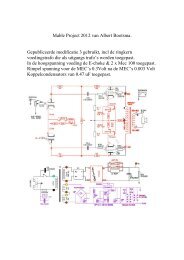
How to make Super-Triode without a separate cathode winding?:<br />
As said before, the output transformer inside the UL40-S2 contains no separate cathode winding. I<br />
do need extra local feedback to change the Ultra-Linear tube into Triode behavior without loosing<br />
output power. Fortunately there exists another technique of local feedback. This technique applies<br />
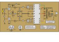
local feedback at the control grid of the power tube instead of at the cathode. See for details figure<br />
3.<br />
R1<br />
R2<br />
C<br />
1<br />
input<br />
100 pF<br />
2<br />
100 pF<br />
3<br />
Vht<br />
4<br />
inverse<br />
5<br />
input<br />
R1<br />
R2<br />
C<br />
Fig. 3 : New Super-Triode circuit with control grid feedback. Copyright 2004 Van<strong>der</strong>veen<br />
A certain part of the alternating voltage at the anode is sent to the control grid through a voltage<br />
divi<strong>der</strong> (created by R1 and R2. Forget C for this moment. Its function only is to stop the DC voltage<br />
at the anode to enter the control grid). When I make the voltage division through R1 and R2 equal<br />
to the turns ratio of the cathode winding to the primary winding, then the control grid will receive the<br />
same amount of local feedback as in the Super-Triode circuit. So, only with two resistors (and a<br />
capacitor as DC stopper) I can reach the same goal as with a separate cathode winding.<br />
Is this way of thinking correct? Yes, else I would not have published. Also, there is nothing new<br />
un<strong>der</strong> the sun. See my book “Mo<strong>der</strong>n High-End Valve Amplifiers based on toroidal output<br />
transformers”, page 240, figure 20.1. There the resistors R5 and R6 perform the same trick.<br />
What resistance should the resistors R1 and R2 have in the UL40-S2? Look into the schematics of<br />
this amplifier, to see that R1 in figure 3 equals R12 and R22 in the UL40-S2, while R2 and C in<br />
figure 3 have to be added as new components in the UL40-S2.<br />
R12 (in UL40-S2) = 82k (or series circuit of 47k resistor + 50k trim pot, see later)<br />
R22 (in UL40-S2) = 100k<br />
In parallel to R12 and R22 a Styroflex capacitor of 100 pF (see remarks 28-11-04)<br />
Rnew (in UL40-S2) = 2M2 (This Rnew equals R2 in figure 3)<br />
Cnew (In UL40-S2) = 10nF/1000V (This Cnew equals C in figure 3).<br />
Why do R12 and R22 not have the same resistance? The output impedance of the upper halve of<br />
the phase splitter (6N1P) has an effective plate resistance of about 18k. This resistance is in series<br />
with R12, meaning that R12 + 18k = R22. The output impedance of the lower halve of the phase<br />
splitter is negligible due to the large amount of local feedback around this lower halve circuit.<br />
Therefore R22 does not need extra compensation. The resistors R12 and R22 should be ¼ Watt<br />
power resistors. The capacitor C can be or<strong>der</strong>ed at Farnell, or<strong>der</strong> number 106-364 (or<strong>der</strong> per 5<br />
pieces).