DRAFT Tentlabs Application Note AN.05 â Negative Bias Supply
DRAFT Tentlabs Application Note AN.05 â Negative Bias Supply
DRAFT Tentlabs Application Note AN.05 â Negative Bias Supply

You also want an ePaper? Increase the reach of your titles
YUMPU automatically turns print PDFs into web optimized ePapers that Google loves.
<strong>DRAFT</strong><br />
<strong>Tentlabs</strong> <strong>Application</strong> <strong>Note</strong> <strong>AN.05</strong> – <strong>Negative</strong> <strong>Bias</strong> <strong>Supply</strong>
Introduction<br />
This <strong>Note</strong> applies to <strong>Tentlabs</strong> negative bias supply, version V1.0 and later,<br />
delivered from February 2008 onwards. It shows how:<br />
• They work in general<br />
• To connect them in tube amplifiers<br />
An FAQ is added to help trouble shooting, and the specifications are listed<br />
for reference.<br />
The advised colors for connections are given in this note, and can be<br />
found here for reference.<br />
Purpose<br />
The <strong>Tentlabs</strong> / Vanderveen bias supply is designed to bias (output) tubes,<br />
such that their operating point(s) remain stable, independent of tube age,<br />
mains voltage variations and music signals, without affecting the musical<br />
and technical qualities of the amplifier.<br />
The supplies generate a very low noise output, while maintaining the tube<br />
at its’ operating point, i.e. the standing current remains stable. Result<br />
areas are:<br />
• Higher resolution and correct staging due to lower hum and noise level<br />
• Better bass due to near perfect (
Technology<br />
The module contains an integrated negative power supply, which is<br />
properly filtered and stabilized to achieve clean input voltages for 4<br />
measurement-sections (each tube needs its’ own section). These measure<br />
the actual tube current around a very small window around the bias.<br />
The output signal of each channel is then fed to the grid of the tube, such<br />
that the tube bias is set at the required current.<br />
The maximum output voltage is -160V, enabling the use of virtually any<br />
tube including the famous 211 or a 845. Every tube can be biased up to<br />
175mA. The outputs of the module provide linear and low output<br />
impedance to avoid interaction with the preceding driver stage driving the<br />
power tubes. Each of the 4 outputs can sink and source 1.5mA, allowing<br />
the use of relatively low grid resistors, if required.<br />
The modules are tested and factory adjusted to 40mA each tube. Prior to,<br />
or after installation, the bias can be adjusted to customer requirements.<br />
Installing the module<br />
WARNING<br />
Prior to all installations, measurements and adjustments make sure the<br />
amplifier is switched off and no high voltage is present in the amplifier.<br />
Procedure<br />
This <strong>Application</strong> <strong>Note</strong> describes the installation, and contains the following<br />
steps:<br />
• Check of bias conditions – original amplifier<br />
• Module placement<br />
• Input wiring<br />
• Output wiring<br />
• Electrical check – no tubes applied<br />
• Cathode current check - tubes applied
<strong>Bias</strong> measurement – original amplifier<br />
The bias module has 2 output (grid) voltage ranges. One of these ranges<br />
best suits the application. The ranges are:<br />
1: -85V to -2V<br />
2: -160V to -2V<br />
Prior to installing the module, the grid to cathode voltages of the original<br />
amplifier should be measured, to choose the correct voltage range for the<br />
new module.<br />
Use a multi-meter (with at least 10M-ohm input impedance), and set the<br />
input range to 200Vdc. Connect the ground wire to the cathode of one<br />
tube, and the red wire to the grid of the same tube. Use clips to connect<br />
the meter probes.<br />
Take your hands off, and switch on the amplifier. After stabilization, read<br />
the meter and write down the value. These values may differ from tube to<br />
tube, but we need a ballpark figure. Suppose you measure -47V for a<br />
KT88 or EL34. In that case you can safely use the 1 st range (-85V to -2V).<br />
But, in the case of a 300b, you could measure -78V. Although -78V is<br />
within the range -85V to -2V, we advise the use of the 2 nd range (-160V<br />
to -2V) to allow for enough adjustment headroom for the module. In<br />
general, make sure to have 10% headroom.<br />
Set 2 jumpers to select the correct range, according the figure below:
Module placement<br />
Carefully cut the remaining connections between the boards, using an<br />
appropriate saw. Finish both boards, such that no sharp edges remain.<br />
Find a place to mount the control part close to the tubes, the power<br />
supply part can be mounted elsewhere. Do position both boards such that<br />
the component sides are easy to reach.<br />
Mount both boards using standoffs and assure that:<br />
• Both boards are at least 6 mm above any conducting part<br />
• The power supply part is not mounted close to heat sources<br />
• The control module is mounted close to the power tube sockets<br />
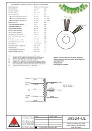
After installation, the boards shall be interconnected, using 4 wires (about<br />
0.15mm diameter) between connectors J4 and J5. Make sure to respect<br />
the wire order; do not mix the wires.<br />
To avoid errors, the wires at both connectors are numbered (1 to 4) on<br />
both boards. Connect wire 1 to wire 1, wire 2 to 2 etcetera. It helps to use<br />
different colors, and follow the colors of the rainbow, for instance. Below<br />
drawing indicates inter-wiring.<br />
Control<br />
part<br />
Power<br />
supply
Mains Input wiring<br />
The bias module needs mains voltage to operate. The mains input wiring<br />
is not limited to length.<br />
Input voltage requirements<br />
Input AC voltage<br />
• 115V setting: 105 to 130V<br />
• 230V setting: 210 to 260V<br />
WARNING<br />
Operating your amplifier without the mains connected to the bias module<br />
will damage your tubes.<br />
Make sure the bias module is not switched off in case your amplifier is<br />
switched into standby mode.<br />
The mains input needs to be wired according your countries mains<br />
voltage.<br />
- 115V operation: place 2 wire links as shown left<br />
- 230V operation: place 1 wire link according the picture right<br />
For your convenience, the wire links are indicated at the module as well.
Input wiring - Ground<br />
The bias module needs to be connected to ground, to enable current to<br />
flow. This is very important. Find the ground connection where normally<br />
the cathode resistors used to be connected. Connect a single wire from<br />
that point to either one of the ground inputs at connector J1. Use isolated<br />
wire (1mm), preferably black.<br />
Input wiring – High voltage<br />
The module senses the high voltage, in order to provide a slow start of<br />
the bias current settings, only after high voltage is present. Therefore the<br />
high voltage of the output stage needs to be connected to the HV input of<br />
the module, at the HV input of connector J1. Use isolated wire (1mm),<br />
preferably red.<br />
Input wiring – Cathodes<br />
First, we analyze the original cathode connections of the output tubes.<br />
They use either:<br />
A relatively big cathode resistor usually decoupled with a capacitor. In this<br />
case the grid resistor goes to ground.<br />
or<br />
A small (say 10 ohm) resistor connected to ground. In this case the grid<br />
resistor goes to a negative bias voltage, usually adjustable with a<br />
trimmer.<br />
Cut the original cathode connection; Trace the cathode connection from<br />
the tube socket to the original cathode resistor and cut the wire or trace<br />
close to the socket(s). You may leave the original cathode resistors /<br />
capacitors in place, but make sure no loose wires stay hanging around in<br />
your amplifier.<br />
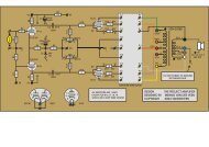
For your reference, follow the drawing at the next page. For the sake of<br />
clarity, only one tube is shown, but up to 4 tubes can be connected to the<br />
module.
Connect each cathode to a cathode connection of the bias module. Use<br />
a yellow wire (0.5mm). Keep a logical connection, i.e. from left to right.<br />
You may want to number the tubes, according the numbering of the<br />
sections on the module.<br />
C<br />
R<br />
Output wiring – Grids<br />
The original grid resistors of the output tubes used to be connected to<br />
either:<br />
Ground<br />
or<br />
A negative bias voltage<br />
Keep the grid resistor connected to the grid (or grid stopper resistance –<br />
not shown) and cut the grid resistor connection to either ground or<br />
negative voltage; this is best done by following the grid connection from<br />
the tube socket onwards.<br />
Connect each grid resistor to a grid connection of the bias module. Use<br />
isolated green wiring (0.5mm), and respect the order of the connections<br />
earlier made………<br />
Warning<br />
The cathode and grid of any tube shall be connected to the same section<br />
of the module<br />
If grids and cathodes are mixed up, your tubes will be overloaded after<br />
switching on.
Testing time<br />
Remove all output tubes from your amplifier. Put the amp on its feet, and<br />
connect the multimeters’ black probe to ground (ground speaker binding<br />
posts work fine here).<br />
Lookup the tube socket connections for cathodes and grids. Be aware to<br />
count counterclockwise when looking at the tube side of the sockets.<br />
Write down the connections, i.e for an EL34 cathode = pin 8, grid = pin 5.<br />
Keep the amplifier switched off.<br />
Cathode connections check<br />
Switch the meter to ohms, range 200 ohm. Check each cathode<br />
connection, it should indicate 10 ohm.<br />
Grid connections check<br />
Set the multimeter to DC volts, range 200V or higher. Put the red probe in<br />
the grid connection of the tube socket.<br />
Switch the amplifier on.<br />
At first the voltage should be fully negative (-160V or -85V, depending on<br />
the selected range). After about 1 minute, the negative voltage should<br />
become less and less, and approach near zero volt (usually -2V).<br />
Repeat this grid connection check for each output tube. Switch off the<br />
amp, wait for 5 minutes and check next grid.<br />
Warning<br />
If the voltage is not fully negative at first startup, an error is present. Do<br />
not proceed, as this may damage your tubes or amplifier
Indicators<br />
The following LEDs indicators are present on the board:<br />
Both power on LEDs immediately light up after switch on<br />
The operate LED comes on after some 45s after power up, when the units<br />
starts to regulate the tube current.
Switch the amplifier off.<br />
Double check whether you haven’t mixed up cathodes and grids by<br />
following each pair of wires from tube socket to module.<br />
The bias module is factory adjusted so that the output tube bias currents<br />
become 40mA. This value can be changed according user requirements,<br />
by tuning trimmer R14:<br />
To decrease the bias current:<br />
To increase the bias current:<br />
Turn the trimmer counterclockwise<br />
Turn the trimmer clockwise<br />
At testpoint J3, an indication of the cathode current can be measured; this<br />
is explained at the next page.
Cathode current adjustment<br />
The amplifier is still without output tubes. Put the amp down, or on its<br />
side, such that the multimeters black probe can be connected to the<br />
remaing ground connection of connector J1. Swith the multimeter to a<br />
range of 2Vdc or higher.<br />
Know the required bias value in mA and multiply by 10 to obtain a<br />
reference value in mV. Example:<br />
<strong>Bias</strong> current (each tube): 30 mA. Reference value = 300 mV<br />
Take a screwdriver that allows trimming of trimmer R14 (see drawing at<br />
previous page). Switch the amplifier on, and probe at the reference point<br />
J3. Turn the trimmer until you reach the desired value.<br />
Swith the amplifier off, and put the output tubes back in their sockets.<br />
Cathode current check<br />
Place the amp such that<br />
- It is stable<br />
- The output tubes can remain in place<br />
- Their cathodes can be probed<br />
• Connect the black probe to the module ground, leave the range in<br />
2Vdc.<br />
• Switch the amplifier on, and wait at least 1 minute to let the amps and<br />
currents stabilize.<br />
• Probe each cathode with the red probe. The meter should read the<br />
reference value within 2%. If desired, one may optimize the current<br />
setting a bit.<br />
All cathodes should read the same reference value, usually within 0.5%.<br />
This ends the adjustment procedure, time for some serious listening !<br />
For your convenience, the next page shows a typical application circuit
FAQ<br />
Specifications Electrical<br />
Mechanical<br />
All specs and parameters subject to change without prior notice