DRAFT Tentlabs Application Note AN.05 â Negative Bias Supply
DRAFT Tentlabs Application Note AN.05 â Negative Bias Supply
DRAFT Tentlabs Application Note AN.05 â Negative Bias Supply

Create successful ePaper yourself
Turn your PDF publications into a flip-book with our unique Google optimized e-Paper software.
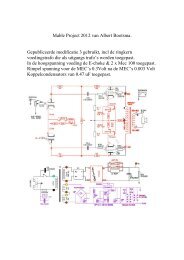
<strong>Bias</strong> measurement – original amplifier<br />
The bias module has 2 output (grid) voltage ranges. One of these ranges<br />
best suits the application. The ranges are:<br />
1: -85V to -2V<br />
2: -160V to -2V<br />
Prior to installing the module, the grid to cathode voltages of the original<br />
amplifier should be measured, to choose the correct voltage range for the<br />
new module.<br />
Use a multi-meter (with at least 10M-ohm input impedance), and set the<br />
input range to 200Vdc. Connect the ground wire to the cathode of one<br />
tube, and the red wire to the grid of the same tube. Use clips to connect<br />
the meter probes.<br />
Take your hands off, and switch on the amplifier. After stabilization, read<br />
the meter and write down the value. These values may differ from tube to<br />
tube, but we need a ballpark figure. Suppose you measure -47V for a<br />
KT88 or EL34. In that case you can safely use the 1 st range (-85V to -2V).<br />
But, in the case of a 300b, you could measure -78V. Although -78V is<br />
within the range -85V to -2V, we advise the use of the 2 nd range (-160V<br />
to -2V) to allow for enough adjustment headroom for the module. In<br />
general, make sure to have 10% headroom.<br />
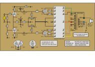
Set 2 jumpers to select the correct range, according the figure below: