DRAFT Tentlabs Application Note AN.05 â Negative Bias Supply
DRAFT Tentlabs Application Note AN.05 â Negative Bias Supply
DRAFT Tentlabs Application Note AN.05 â Negative Bias Supply

Create successful ePaper yourself
Turn your PDF publications into a flip-book with our unique Google optimized e-Paper software.
Cathode current adjustment<br />
The amplifier is still without output tubes. Put the amp down, or on its<br />
side, such that the multimeters black probe can be connected to the<br />
remaing ground connection of connector J1. Swith the multimeter to a<br />
range of 2Vdc or higher.<br />
Know the required bias value in mA and multiply by 10 to obtain a<br />
reference value in mV. Example:<br />
<strong>Bias</strong> current (each tube): 30 mA. Reference value = 300 mV<br />
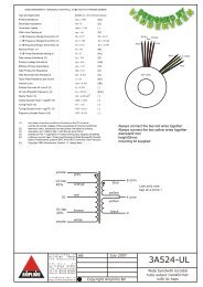
Take a screwdriver that allows trimming of trimmer R14 (see drawing at<br />
previous page). Switch the amplifier on, and probe at the reference point<br />
J3. Turn the trimmer until you reach the desired value.<br />
Swith the amplifier off, and put the output tubes back in their sockets.<br />
Cathode current check<br />
Place the amp such that<br />
- It is stable<br />
- The output tubes can remain in place<br />
- Their cathodes can be probed<br />
• Connect the black probe to the module ground, leave the range in<br />
2Vdc.<br />
• Switch the amplifier on, and wait at least 1 minute to let the amps and<br />
currents stabilize.<br />
• Probe each cathode with the red probe. The meter should read the<br />
reference value within 2%. If desired, one may optimize the current<br />
setting a bit.<br />
All cathodes should read the same reference value, usually within 0.5%.<br />
This ends the adjustment procedure, time for some serious listening !<br />
For your convenience, the next page shows a typical application circuit