DRAFT Tentlabs Application Note AN.05 â Negative Bias Supply
DRAFT Tentlabs Application Note AN.05 â Negative Bias Supply
DRAFT Tentlabs Application Note AN.05 â Negative Bias Supply

You also want an ePaper? Increase the reach of your titles
YUMPU automatically turns print PDFs into web optimized ePapers that Google loves.
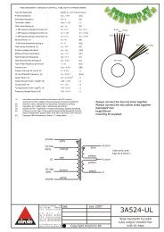
Connect each cathode to a cathode connection of the bias module. Use<br />
a yellow wire (0.5mm). Keep a logical connection, i.e. from left to right.<br />
You may want to number the tubes, according the numbering of the<br />
sections on the module.<br />
C<br />
R<br />
Output wiring – Grids<br />
The original grid resistors of the output tubes used to be connected to<br />
either:<br />
Ground<br />
or<br />
A negative bias voltage<br />
Keep the grid resistor connected to the grid (or grid stopper resistance –<br />
not shown) and cut the grid resistor connection to either ground or<br />
negative voltage; this is best done by following the grid connection from<br />
the tube socket onwards.<br />
Connect each grid resistor to a grid connection of the bias module. Use<br />
isolated green wiring (0.5mm), and respect the order of the connections<br />
earlier made………<br />
Warning<br />
The cathode and grid of any tube shall be connected to the same section<br />
of the module<br />
If grids and cathodes are mixed up, your tubes will be overloaded after<br />
switching on.