pdf version - Menno van der Veen
pdf version - Menno van der Veen
pdf version - Menno van der Veen

You also want an ePaper? Increase the reach of your titles
YUMPU automatically turns print PDFs into web optimized ePapers that Google loves.
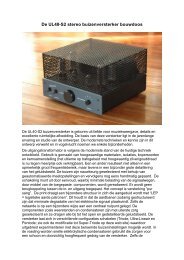
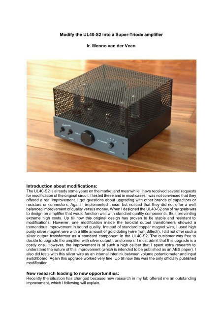
Modify the UL40-S2 into a Super-Triode amplifier<br />
Ir. <strong>Menno</strong> <strong>van</strong> <strong>der</strong> <strong>Veen</strong><br />
Introduction about modifications:<br />
The UL40-S2 is already some years on the market and meanwhile I have received several requests<br />
for modification of the original circuit. I tested these and in most cases I was not convinced that they<br />
offered a real improvement. I got questions about upgrading with other brands of capacitors or<br />
resistors or connectors. Again I implemented those, but noticed that they did not offer a well<br />
balanced improvement of quality versus money. When I designed the UL40-S2 one of my goals was<br />
to design an amplifier that would function well with standard quality components, thus preventing<br />
extreme high costs. Up till now this original design has proven to be stable and resistant to<br />
modifications. However, one modification inside the toroidal output transformers showed a<br />
tremendous improvement in sound quality. Instead of standard copper magnet wire, I used high<br />
purity silver magnet wire with a little amount of gold doting (wire from Siltech). I did not offer such a<br />
silver output transformer as a standard component in the UL40-S2. The customer was free to<br />
decide to upgrade the amplifier with silver output transformers. I must admit that this upgrade is a<br />
costly one. However, the improvement is of such a high caliber that I spent extra research to<br />
un<strong>der</strong>stand the nature of this improvement (which is intended to be published as an AES paper). I<br />
also did tests with this silver wire as an internal interlink between volume potentiometer and input<br />
switchboard. Again this upgrade worked very fine. Up till now this was the only officially published<br />
modification.<br />
New research leading to new opportunities:<br />
Recently the situation has changed because new research in my lab offered me an outstanding<br />
improvement, which I following will explain.
I always used the UL40-S2 in its Ultra-Linear mode, because I needed the large output power of 29<br />
Watt for my loudspeakers. In the Triode mode the sound quality was better, but the output power<br />
went down to a mere 15 Watt, which was too little in my applications. What I really would like to have<br />
is a smart invention that would offer me 29 Watt Ultra-Linear output power with Triode mode quality.<br />
But we all know that inventions only come when their time is right.<br />
Meanwhile I was busy in my lab with a new research about a large general system, that contains all<br />
possible topologies and concepts of valve amplifiers. The system not only covers Single-Ended and<br />
Push-Pull amplifiers, but also Paralleled-Push-Pull plus balanced circuits like the Circlotron and<br />
Unity-Coupled plus many other smart vacuum tube amplifier inventions. This new approach clearly<br />
showed that the different valve amp topologies all use a certain amount of local negative feedback<br />
around the output transformer and the power tubes. Following I tested many topologies in a<br />
universal amplifier (almost equal to the UL40-S2). These tests clearly taught me that there are two<br />
winners: the pure triode circuit (SE or PP, both are excellent) and the Super-Triode circuit which I<br />
had invented and published in 1998. Comparing these two winners, it became clear that their sound<br />
quality was equal, but the output power of the Super-Triode was twice the power of the Triode<br />
circuit.<br />
Knowing this, I was close to the new invention which I will discuss. The only issue I had to solve was<br />
the implementation of the Super-Triode concept into the original UL40-S2.<br />
From Triode to Super-Triode:<br />
The major difference between Triode and Super-Triode circuitry is that the Triode only uses one<br />
control grid, while the Super-Triode uses a control grid and a screen grid connected to the Ultra-<br />
Linear taps on the primary of the output transformer. See the figures 1 and 2 for more information.<br />
input<br />
1<br />
3<br />
Vht<br />
inverse<br />
input<br />
5<br />
Fig.1 : Basic Triode circuit. Copyright 2004 Van<strong>der</strong>veen
1<br />
input<br />
2<br />
3<br />
Vht<br />
4<br />
inverse<br />
input<br />
5<br />
Fig. 2 : Basic Super-Triode circuit. Copyright 2004 Van<strong>der</strong>veen<br />
The standard output transformer (VDV6040PP or PAT4002) inside the UL40-S2 does have Ultra-<br />
Linear taps (taps 2 and 4) on the primary. However, this output transformer does not have a<br />
separate cathode feedback winding. Would this mean that the Super-Triode circuit is not possible in<br />
the UL40-S2? By experience I know that the words “not possible” ask for closer attention, and<br />
therefore I focused on finding an alternative solution. Fortunately my “new system” showed me the<br />
way how to solve this problem, and a new invention was the result. I now will discuss this new<br />
modification that will change the UL40-S2 into a Super-Triode amplifier. The price of this<br />
modification is little, only a few Euros, while the net result gives a tremendous improvement in sound<br />
quality.<br />
Background of the modification:<br />
When we convert the UL40-S2 amplifier into a Triode amplifier, we connect the screen grid to the<br />
anode in each EL34 pentode. This is how a pentode is converted into a triode. This simple action<br />
delivers two results. Firstly, the lines in the Ia-Vak-Vgk characteristics get closer toward each others<br />
and move to the right side, resulting in a smaller maximum output power. Secondly, the lines in the<br />
characteristics get a steeper slope. This means that the effective plate resistance of each EL34 has<br />
become smaller, resulting in a larger and better damping of the loudspeaker (higher damping<br />
factor). How can a change in screen grid connection have such a clear influence? Because the<br />
screen grid functions like a weak control grid on which a certain amount of local feedback is applied.<br />
The screen grid receives as a local feedback signal the same alternating voltage as present on the<br />
anode.<br />
However, when we connect the screen gird to the Ultra-Linear tap (tap 2 or 4) on the output<br />
transformer, then only 1/3 of the alternating voltage at the anode is sent to this screen grid as a<br />
local feedback signal. This is because the UL-tap is placed on 1/3 of each primary halve. Compared<br />
to the Triode situation we now have less (1/3 part) local feedback. The lines in the Ia-Vak-Vgk<br />
characteristics do hardly move to the right side of these characteristics, which means that the output<br />
power stays large. Their slope is a little less steep as compared to triode, but much steeper as<br />
compared to pentode, resulting in a reasonable amount (although less as compared to triode) of<br />
damping of the loudspeaker.<br />
Compared to Ultra-Linear, the essence of the Super-Triode circuitry is that I apply extra local<br />
feedback at the cathode. I connect each cathode to a separate winding on the output transformer.<br />
This gives me the extra local feedback to make the power tube function as a Triode, while the<br />
output power stays large (the position of the lines in the Ia-Vak-Vgk characteristics is only<br />
determined by the local feedback on the screen grids and not by the local feedback on the<br />
cathode).
How to make Super-Triode without a separate cathode winding?:<br />
As said before, the output transformer inside the UL40-S2 contains no separate cathode winding. I<br />
do need extra local feedback to change the Ultra-Linear tube into Triode behavior without loosing<br />
output power. Fortunately there exists another technique of local feedback. This technique applies<br />
local feedback at the control grid of the power tube instead of at the cathode. See for details figure<br />
3.<br />
R1<br />
R2<br />
C<br />
1<br />
input<br />
100 pF<br />
2<br />
100 pF<br />
3<br />
Vht<br />
4<br />
inverse<br />
5<br />
input<br />
R1<br />
R2<br />
C<br />
Fig. 3 : New Super-Triode circuit with control grid feedback. Copyright 2004 Van<strong>der</strong>veen<br />
A certain part of the alternating voltage at the anode is sent to the control grid through a voltage<br />
divi<strong>der</strong> (created by R1 and R2. Forget C for this moment. Its function only is to stop the DC voltage<br />
at the anode to enter the control grid). When I make the voltage division through R1 and R2 equal<br />
to the turns ratio of the cathode winding to the primary winding, then the control grid will receive the<br />
same amount of local feedback as in the Super-Triode circuit. So, only with two resistors (and a<br />
capacitor as DC stopper) I can reach the same goal as with a separate cathode winding.<br />
Is this way of thinking correct? Yes, else I would not have published. Also, there is nothing new<br />
un<strong>der</strong> the sun. See my book “Mo<strong>der</strong>n High-End Valve Amplifiers based on toroidal output<br />
transformers”, page 240, figure 20.1. There the resistors R5 and R6 perform the same trick.<br />
What resistance should the resistors R1 and R2 have in the UL40-S2? Look into the schematics of<br />
this amplifier, to see that R1 in figure 3 equals R12 and R22 in the UL40-S2, while R2 and C in<br />
figure 3 have to be added as new components in the UL40-S2.<br />
R12 (in UL40-S2) = 82k (or series circuit of 47k resistor + 50k trim pot, see later)<br />
R22 (in UL40-S2) = 100k<br />
In parallel to R12 and R22 a Styroflex capacitor of 100 pF (see remarks 28-11-04)<br />
Rnew (in UL40-S2) = 2M2 (This Rnew equals R2 in figure 3)<br />
Cnew (In UL40-S2) = 10nF/1000V (This Cnew equals C in figure 3).<br />
Why do R12 and R22 not have the same resistance? The output impedance of the upper halve of<br />
the phase splitter (6N1P) has an effective plate resistance of about 18k. This resistance is in series<br />
with R12, meaning that R12 + 18k = R22. The output impedance of the lower halve of the phase<br />
splitter is negligible due to the large amount of local feedback around this lower halve circuit.<br />
Therefore R22 does not need extra compensation. The resistors R12 and R22 should be ¼ Watt<br />
power resistors. The capacitor C can be or<strong>der</strong>ed at Farnell, or<strong>der</strong> number 106-364 (or<strong>der</strong> per 5<br />
pieces).
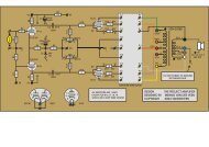
How to implement this modification? Remove R12 and R22 (both were 1k) in the UL40-S2 and place<br />
there the new resistors R12 = 82k and R22 = 100K. Now add above the PCB the series circuit of<br />
Rnew = 2M2 and Cnew = 10nF. See for details figure 4.<br />
R12 = 82 k<br />
R12 = 82 k<br />
2M2<br />
f U+ S2 GND<br />
2M2<br />
10 nF 10 nF<br />
M3<br />
5<br />
R12<br />
100 pF<br />
P4<br />
UL40S2<br />
COPYRIGHT 2000<br />
IR BURO<br />
VANDERVEEN<br />
PLUS<br />
HIER<br />
COMPONENTENKANT<br />
Plaats hier R-C<br />
Sol<strong>der</strong>en, zie manual<br />
R22<br />
C1<br />
-<br />
C1<br />
- R22<br />
100 pF +<br />
+<br />
100 pF<br />
P3<br />
P2<br />
P4<br />
P3<br />
R12<br />
100 pF<br />
5<br />
M3<br />
10 nF<br />
10 nF<br />
2M2<br />
M3<br />
2M2<br />
M3<br />
R22 = 100k<br />
40s2-4 Copyright 2004 Ir. Bureau Van<strong>der</strong>veen : 17-11-04<br />
R22 = 100k<br />
Figure 4: The modification of the UL40-S2 into a Super-Triode amplifier (28-11-04)<br />
What are the results of this modification?:<br />
Let me start with some measurements. The output power equals 29 Watt into a 4 Ohm loudspeaker.<br />
This is the same as with the former Ultra-Linear circuit. The output impedance at the loudspeaker<br />
terminals equals 2.5 Ohm. This is equal to a damping factor of DF = 8 / 2.5 = 3.2 and this is real<br />
Triode behavior, as expected. The subjective sound character of the amp really is pure Triode. The<br />
sound is very clean, with deep depth in the soundstage and an open detailed resolution of every<br />
voice and instrument. Compared to this excellent result, the Ultra-Linear mode sounded more<br />
muddy. The dynamic character (output power) of the Ultra-Linear mode was good, and with the<br />
Super-Triode it again is good and powerful (as expected). The bass sounds tight, loud and well<br />
controlled.<br />
But ……., there is always a “but”. Every ad<strong>van</strong>tage comes with a disad<strong>van</strong>tage at another spot. So,<br />
where to look for the disad<strong>van</strong>tage? The frequency range gets more restricted. Before it was –3dB<br />
at 80kHz, now it equals –3dB at 40kHz. The original Super-Triode circuit with cathode winding did<br />
not show such a disad<strong>van</strong>tage. Did I do something wrong? No, because in this new circuit the signal<br />
from phase splitter to EL34 tubes first has to pass rather large resistors (approx.100k). These<br />
resistors create a low pass filter with the input capacitance (a few picoFarad) at the control grid of<br />
the EL34, thus restricting the –3dB frequency range to 40kHz. I decided to leave this “disad<strong>van</strong>tage”<br />
as is, because with CD’s (they are restricted to 22kHz) I have not been able to hear any<br />
disad<strong>van</strong>tage in this respect. I only hear clear improvement. I know that when I would try to solve this<br />
disad<strong>van</strong>tage as well, it would create other problems and no further improvement. So, let it be.
An unexpected extra ad<strong>van</strong>tage:<br />
While building and testing the modification in my amplifier, I did not directly implement R12 = 82k,<br />
but first used a series test circuit of R12 is 47k plus a trim potentiometer of 50k. I now call this 50k<br />
trim pot P5. See figure 5 and the pictures.<br />
P5 = 50k<br />
47k + P5 = R12<br />
P5 = 50k<br />
10 nF 10 nF<br />
2M2<br />
M3<br />
2M2<br />
M3<br />
5<br />
47k<br />
R22<br />
100 pF<br />
f U+ S2 GND<br />
100 pF 100 pF<br />
P5<br />
P5<br />
P4<br />
P3<br />
UL40S2<br />
COPYRIGHT 2000<br />
IR BURO<br />
VANDERVEEN<br />
C1<br />
-<br />
+<br />
PLUS<br />
HIER<br />
P2<br />
COMPONENTENKANT<br />
Plaats hier R-C<br />
Sol<strong>der</strong>en, zie manual<br />
C1<br />
-<br />
+<br />
P4<br />
P3<br />
47k<br />
R22<br />
100 pF<br />
5<br />
2M2<br />
M3<br />
2M2<br />
M3<br />
10 nF<br />
10 nF<br />
R22 = 100k<br />
40s2-5 Copyright 2004 Ir. Bureau Van<strong>der</strong>veen; 15-11-04<br />
R22 = 100k<br />
Fig. 5: The modification with R12 = 47k plus a series trim pot P5 (28-11-04)
With this trim pot P5 I could compensate very careful for the difference in output impedances of both<br />
halves of the phase splitter. While doing so, I noticed something unexpected to happen.<br />
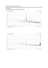
I was measuring the output signal at the speaker terminals with an oscilloscope (5mV/div.) There<br />
was no signal present at the amplifiers input. I noticed that the hum-level at the output changed<br />
while changing the resistance of P5. Before, with trim pot P4, I carefully had made the quiescent<br />
currents equal of both EL34 tubes per channel with an accuracy of 0.1 mA. This can be checked by<br />
measuring equal DC voltage drop over the resistors R14 and R21 (or zero Volt between the two<br />
EL34 cathodes). Consequently there was no unbalance in quiescent currents and this could not<br />
cause this hum. This effect made me aware of something very important. The supply voltage Vo<br />
always has a ripple voltage on top of the DC voltage Vo. This ripple voltage only balances to zero in<br />
the balanced output transformer when both EL34 tubes have exactly the same effective plate<br />
resistance. From the former given description, it is un<strong>der</strong>standable now that this effective plate<br />
resistance can be changed with the resistance of trim pot P5.<br />
Why is this so important? Because I have never seen any valve circuit in which you can<br />
independently change three parameters of a power vacuum tube. See the original UL40-S2<br />
schematics:<br />
Trim pot P4 makes the quiescent currents of both power tubes equal<br />
Trim pot P5 makes the plate resistances of both power tubes equal<br />
Trim pot P3 makes the effective amplification of both power tubes equal<br />
This means that we can trim the power tubes to exactly equal behavior on three independent<br />
parameters. Such a feature I have never seen before. Therefore I now give a very precise<br />
procedure how to bring the Super-Triode UL40-S2 amplifier to optimal balanced behavior.<br />
1) Connect a DC-voltmeter (200mV-setting) to both cathodes of the two EL34 tubes. Trim with P4<br />
for zero voltmeter reading. Then both quiescent currents are equal.<br />
2) Connect an oscilloscope (5mV/div.) to the output of the amplifier. Trim with P5 for minimal humlevel<br />
(100 or 120 Hz, hum smaller than 1 mV effective). Make sure that P1 (at amplifiers input) is<br />
closed to prevent any input hum blurring this measurement. Now both plate resistances are equal.
3) Connect an oscillator (1kHz sinus) to the amplifier input. Load the amplifier output with a 4 Ohm<br />
dummy load. Check the output with an oscilloscope. Slowly turn the input potentiometer (volume<br />
control) P1 to higher setting up till the output voltages is at the edge of clipping. Now trim with P3 for<br />
symmetrical clipping. (It is interesting, during this procedure, to listen to the soft sound generated<br />
by the output transformer. It is noticeable that the second harmonics of 1kHz disappears at correct<br />
setting of P3). An earlier given test method for trimming P3 with a 100Hz square wave now will give a<br />
very stable result without any overshoot because the EL34 tubes behave exactly equal.<br />
4) Repeat the above given procedure for both channels of the stereo amplifier. Connect dummy<br />
loads of 4 Ohm to the outputs of the two channels and connect a two channel oscilloscope to the<br />
amplifier outputs. Set the volume potentiometer P1 at 3.00 o’clock. Apply an equal input of 1kHz<br />
sinus to both channels up till the output level at both outputs equals 8 Volt peak to peak. Trim P2<br />
for equal output voltage. With this procedure the left-right balance has been corrected. (Why P1<br />
at 3 o’clock? Because the Alps volume controls have some deviation between its two channels<br />
above 3 o’clock. The mostly used volume setting is below 3 o’clock (I mostly listen at 12 o’clock) , so<br />
we should make the left-right balance optimal in that range of P1).<br />
Summary:<br />
The Super-Triode modification gives the UL40-S2 amp maximum output power of 29 Watt per<br />
channel, with the damping and clarity of a pure superb sounding Triode amplifier. The modification<br />
destroys nothing in the amp. Only a few inexpensive components have to be added or changed in<br />
value. Especially trim pot P5 offers new ways to balance the power tubes of each channel on three<br />
independent parameters. After this balancing the distortion is truly minimal, resulting in an extreme<br />
open and clean and powerful sound reproduction.<br />
I wish you much success with this simple and very good sounding modification.<br />
Zwolle; 12-october 2004; Ir. <strong>Menno</strong> <strong>van</strong> <strong>der</strong> <strong>Veen</strong>, Ir. Bureau Van<strong>der</strong>veen<br />
This modification and publication: Copyright 2004 Ir. Bureau Van<strong>der</strong>veen;<br />
Super-Triode: Copyright & Registered1998 Ir. Bureau Van<strong>der</strong>veen
Remark (Nov-28-2004):<br />
A customer told me that his amplifier started to oscillate (at 640 kHz) with the modification. I<br />
researched his amp and found the cause. There was a capacitive feedback between the screen<br />
grid G2 and the control grid G1, which was not damped because R12 and R22 have much larger<br />
resistances in this modification (about 100kOhm) compared to the old situation (where R12 and R22<br />
were 1kOhm). I stopped this oscillation by placing capacitors of 100 pF (Styroflex) in parallel with<br />
R12 and R22. To be sure that such an oscillation does not occur (it did not happen in my amplifier<br />
which I used to test the modification), I placed these new 100 pF capacitors in all the rele<strong>van</strong>t<br />
drawings and schematics. The 100 pF capacitors have the extra ad<strong>van</strong>tage that they widen the –<br />
3dB bandwidth again to 70kHz, because they compensate the EL34’s input capacitance between<br />
control grid and cathode.<br />
UL40-S modification; See "Mo<strong>der</strong>n High-End Valve Amplifiers ..." page 199<br />
Cnew<br />
UL40-S modification<br />
R10 82 k<br />
Rnew<br />
100pF<br />
Rnew<br />
Cnew<br />
R16<br />
100 k<br />
100pF<br />
R16<br />
100 k<br />
Rnew<br />
Cnew<br />
100pF<br />
100pF<br />
Cnew<br />
Rnew<br />
R10<br />
82 k