MEC-manual-UK.pdf - Menno van der Veen
MEC-manual-UK.pdf - Menno van der Veen
MEC-manual-UK.pdf - Menno van der Veen

Create successful ePaper yourself
Turn your PDF publications into a flip-book with our unique Google optimized e-Paper software.
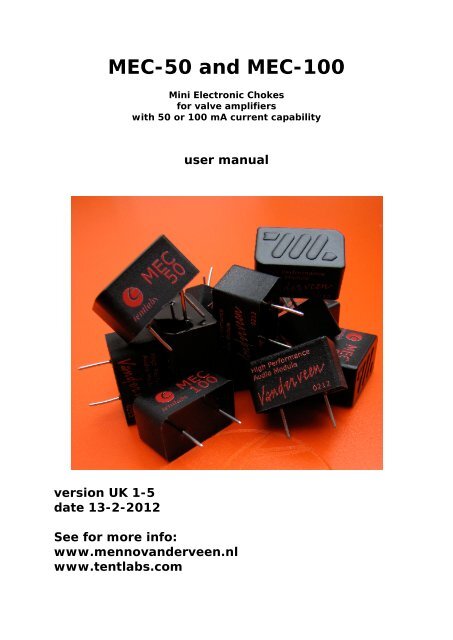
<strong>MEC</strong>-50 and <strong>MEC</strong>-100<br />
Mini Electronic Chokes<br />
for valve amplifiers<br />
with 50 or 100 mA current capability<br />
user <strong>manual</strong><br />
version <strong>UK</strong> 1-5<br />
date 13-2-2012<br />
See for more info:<br />
www.menno<strong>van</strong><strong>der</strong>veen.nl<br />
www.tentlabs.com
1- Introduction<br />
In the power supply of valve amplifiers we have noticed that chokes<br />
suppress hum and noise better than the standard configuration with<br />
capacitors plus resistor. Chokes sound softer and mil<strong>der</strong>, you can hear<br />
more details in the sound stage. This observation was the reason why ir.<br />
bureau Van<strong>der</strong>veen and Tentlabs decided to develop new miniature<br />
electronic chokes for valve pre amplifiers and small power amplifiers.<br />
The <strong>MEC</strong>-50 and <strong>MEC</strong>-100 are very small electronic chokes which remove<br />
hum and distortions from the high voltage supply lines in valve amplifiers.<br />
The <strong>MEC</strong>-50 can handle 50 mA maximum while the <strong>MEC</strong>-100 can handle<br />
100 mA. The maximum high supply voltage should be below 800 Vdc.<br />
There is an arrow on the <strong>MEC</strong>'s indicating the direction of current flow.<br />
Reverse connection does not damage the <strong>MEC</strong>'s; at the output the high<br />
voltage is present. However, without the reduction of hum.
See the schematic below for a standard application.<br />
figure 1: connections on the <strong>MEC</strong> + current direction arrow<br />
The <strong>MEC</strong>-50 is meant for pre amplifier and driver stages while the <strong>MEC</strong>-<br />
100 is designed for small class A SE amplifiers with the 300B or 2A3 or<br />
EL84 power valves as examples. Small push-pull power amplifiers with<br />
maximum current demand below 100 mA are also possible, like 2 x EL84<br />
or 2 x ECL86. For currents larger than 100 mA we earlier designed the E-<br />
choke.<br />
The <strong>MEC</strong>'s have only two taps: their input and output. There is no<br />
connection to ground. They fit in the standard pi-circuit, where after<br />
rectification the supply voltage is buffered in C1, followed by the <strong>MEC</strong> and<br />
C2. This application is as with standard chokes. However, the <strong>MEC</strong>'s are<br />
much smaller than standard transformer core based chokes. The have no<br />
magnetic leakage fields and they do not hum or rattle. Besides these<br />
important ad<strong>van</strong>tages, they reject noise and hum much better than with<br />
old fashioned chokes. The hum rejection equals a factor 1000 with the<br />
<strong>MEC</strong>-50 and a factor 250 with the <strong>MEC</strong>-100. Read the specs for more<br />
detailed information.<br />
In function the <strong>MEC</strong>'s produce little heat, less than 1 W. Some air flow<br />
cooling is enough to remove this heat.<br />
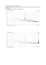
The effective inductance of the <strong>MEC</strong>-50 equals 78 H and for the <strong>MEC</strong>-100<br />
it is 10 H. These large inductances suppress hum and interference signals<br />
with a factor of 1000 (60 dB) and a factor of 250 (48 dB) respectively.<br />
See figure-2 for C1 = C2 = 47 µF and I = 48 mA. The upper curve shows<br />
the voltage ripple at C1 while the lower proves the reduction at C2. At<br />
higher frequencies the ripple becomes smaller than the noise floor<br />
(-140dBV) of the measurement equipment.
figure 2: input (upper curve) and output (lower curve) ripple voltages.<br />
The reduction is at least a factor 1000 for the <strong>MEC</strong>-50<br />
The <strong>MEC</strong>'s are designed for so called C-L-C supplies and not for L-C<br />
supplies. Neither they are meant for transformer anode load applications.<br />
2- Application<br />
Figure 3 shows the first application of the E-choke plus <strong>MEC</strong>'s in the<br />
Van<strong>der</strong>veen UL40-S2 valve amplifier.<br />
figure 3: E-choke and <strong>MEC</strong> in the UL40-S2 amplifier.
Figure 4 explains how to apply the <strong>MEC</strong>-50 in the Van<strong>der</strong>veen MVML05 pre<br />
amplifier.<br />
figure 4: <strong>MEC</strong>-50 in the MCML05 pre amplifier<br />
All that changed is that the C-R-C network has been replaced by a far<br />
more effective C-<strong>MEC</strong>-C pi-filter network with much larger hum<br />
suppression.<br />
100kg<br />
100kg<br />
C1<br />
9<br />
IN-L<br />
150 V 1 1,2mA<br />
2<br />
100nF<br />
2<br />
250VAC 3<br />
1k<br />
VR1a<br />
0,48V<br />
3<br />
V-b ia s R9<br />
TR-1<br />
R1 R3<br />
C13<br />
10uF<br />
16V +<br />
BSP129<br />
D<br />
G<br />
VB3 EL84 / 6BQ5<br />
S 150k 1M<br />
7<br />
C2<br />
9<br />
IN-R<br />
2<br />
6<br />
150 V 1,2mA<br />
100nF<br />
7<br />
250VAC 3<br />
1k<br />
VR1b<br />
0,48V<br />
8<br />
V-b ia s R10<br />
TR-2<br />
R2 R4<br />
C14<br />
10uF<br />
+<br />
16V<br />
1M<br />
1M<br />
BSP129<br />
D<br />
G<br />
S<br />
1k<br />
680R<br />
1k<br />
680R<br />
1k2<br />
1k2<br />
2 x 1,5 mA<br />
150k<br />
TRIM-100k<br />
TRIM-100k<br />
250 V<br />
R15<br />
C5 + C6 + C7 +<br />
22uF<br />
450V<br />
1M<br />
1M<br />
1M<br />
<strong>MEC</strong>-50<br />
VB2 EL84 / 6BQ5<br />
R11<br />
10E<br />
R12<br />
10E<br />
7<br />
260 V<br />
100uF<br />
450V<br />
ORA<br />
RED<br />
ORA<br />
RED<br />
96 mA<br />
T2<br />
OUTPUT<br />
T3<br />
220k 2W<br />
OUTPUT<br />
GRN<br />
BLK<br />
GRN<br />
BLK<br />
<strong>MEC</strong>-100<br />
8 Ohm<br />
0 Ohm<br />
V-b ia s<br />
8 Ohm<br />
0 Ohm<br />
100uF<br />
450V<br />
272 V<br />
630 mA slow<br />
PUR<br />
F2<br />
D1-D4 = 1N4007<br />
D5<br />
F1<br />
1N4004<br />
2 A slow<br />
LED<br />
R16<br />
150<br />
C12<br />
R20<br />
1k<br />
B1-B2-B3<br />
FILAMENT<br />
+ 100uF +<br />
16V<br />
D6<br />
1N4148<br />
C11<br />
100uF<br />
16V<br />
240 V<br />
110 mA<br />
PUR<br />
6,8 V<br />
3 A<br />
T1<br />
POWER<br />
230 V 10 V<br />
BRN<br />
WHT<br />
F3<br />
1 A slow<br />
RED<br />
SW<br />
27E 1W<br />
R17<br />
100nF 630V<br />
C8<br />
MAINS-GND<br />
C HASSIS-GND<br />
AUDIO-GND<br />
Trim TR-1 and TR-2 for 0,48V over R11 and R12<br />
AUREXX CRYSTAL 1 (2011)<br />
mod-0: no NFB: Ao= 667; Z-out= 45 Ohm; 42Hz-35kHz<br />
(-3dB). With NFB: at edge of instability (13-4)<br />
mod-1: R1,2,9,10= 1M-1/2W; R11,12= 150E-1W (14-4)<br />
mod-2: Separate chassis = mains from audio ground<br />
add R17= 27E/1W and C8= 100nF/630V (15-4)<br />
mod-3: add R18,19= 1M-1/2W; no NFB. Z-out= 3 Ohm;<br />
Ao= 24; 10Hz-37kHz (-3dB); Pmax= 2.9W (28-4)<br />
mod-4: with FB+ C9,10= 180pF-Styro.. Z-out= 1.2 Ohm<br />
Ao = 8; 4Hz-60kHz (-3dB); Pmax= 3.4W (11-5)<br />
mod-5: C3,4 = 22uF/63V for first or<strong>der</strong> behavior (18-5)<br />
mod-6: remove R18,19; remove C3,4; R11,12 = 10E<br />
create neg Bias for EL84 (Leon B. 10-6)<br />
mod-7: LED cathode belasting EL84 (Huib)<br />
mod-8: voedings stabilisatie (Arjen)<br />
mod-9: Leon Bemmelmans: I-bron voor ECC83 (25-10)<br />
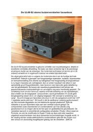
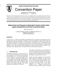
mod-10: <strong>Menno</strong>: <strong>MEC</strong>'s + I-bron + EL84 FB + ECC83<br />
op 1,2 mA, anode op 150V, geen NFB (17-12)<br />
MAINS<br />
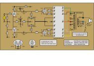
Application of the <strong>MEC</strong>'s in the Aurexx Crystal 1<br />
TubeSociety 2011 project.
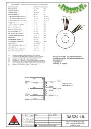
3- Maximum Specifications<br />
The table below shows the important specifications and limits.<br />
Item <strong>MEC</strong>-50 <strong>MEC</strong>-100 Eenheid<br />
maximum current 50 100 mA<br />
maximum Vdc 800 800 V<br />
internal limit for I larger than 68 no mA<br />
inductance 78 10 H<br />
maximum voltage drop @ Imax 12 9 V<br />
short circuit protection no no (1)<br />
protected for inverse connection yes yes<br />
maximum heat production 0,7 0,9 W<br />
minimum capacity C1 27 47 µF (2)<br />
optimal capacity C1 = C2 47 100 µF<br />
dimensions (l-d-h) 27-16-15 27-16-15 mm<br />
pin distance 14.2/.56" 14.2/.56" mm/"<br />
pin length 9 9 mm<br />
pin diameter 1.0 1.0 mm<br />
mass 12 12 gram<br />
price 19 % TAX inclusive 29 34 Euro<br />
(1): Charging C2 too fast can be interpreted as short circuiting the output<br />
of the <strong>MEC</strong>. Therefore guarantee slow charging of C2 to prefend such a<br />
condition.<br />
(2): See chapter 4 for detailed information.<br />
4- Selecting C1 and C2<br />
After rectification the high voltage is buffered in C1 to bring the ripple<br />
voltage magnitude in the working area of the <strong>MEC</strong>.<br />
The best choice is to make C1 and C2 equally large. For a current of 50<br />
mA C1 = C2 = 47 µF is the optimal capacity. For currents I smaller than<br />
50 mA you can select C1 = C2 = I*47/50 (µF, with I in [mA]). Example: I<br />
= 10 mA, then C1 = C2 = 10 µF.<br />
The <strong>MEC</strong>-100 behaves equally with C1 = C2 = 100 µF and for I smaller<br />
than 100 mA: C1 = C2 = I*100/100 (µF, with I in [mA])<br />
Un<strong>der</strong> certain current demand and values of C1 and C2, a kind of<br />
switching on resonance might occur, as shown in figure 5.
figure 5: time behavior <strong>MEC</strong> is not optimal tuned.<br />
To compensate for this, apply an extra resistor at the input or output of<br />
the <strong>MEC</strong>. This resistance of the extra damping resistor easily can be<br />
determined by experiment. Try 10, 47, 100 or 220 Ohm to determine with<br />
the oscilloscope the right damping effect.<br />
figure 6: how to connect a damping resistor (can also be at the <strong>MEC</strong> output).
5- Safety and helpful application remarks<br />
a) Hum reduction (measured up to 1 kHz) a factor of 1000 (<strong>MEC</strong>-50) and<br />
a factor of 250 (<strong>MEC</strong>-100)<br />
b) Voltage drop maximum 12 V (Mec-50) and 9 V (<strong>MEC</strong>-100)<br />
c) Use C1=C2=47 µF as optimal capacitors for the <strong>MEC</strong>-50<br />
Use C1=C2=100 µF as optimal capacitors for the <strong>MEC</strong>-100<br />
d) For smaller I, apply C1=C2=47*I/50 (µF, I in [mA], <strong>MEC</strong>-50)<br />
e) For smaller I, apply C1=C2=100*I/100 (µF, I in [mA], <strong>MEC</strong>-100).<br />
f) The <strong>MEC</strong>'s are designed for class A amplifiers with constant current<br />
demand. C-L-C oscillations as calculated with "PSU designer II) occur,<br />
however, they dampen much faster than calculated. If problematic, apply<br />
a series resistor.<br />
g) V in,max + ripple = 800 V DC . Charge C1,2 slowly at such high voltages, for<br />
instance by means of a rectifier valve which filament heats slowly.<br />
h) The <strong>MEC</strong>'s are not protected for shortcut outputs<br />
i) The <strong>MEC</strong>'s are protected for inversed connection. However, the hum<br />
reduction does not function then.<br />
j) The <strong>MEC</strong>'s are not designed as inductive anode load, nor for so called<br />
L-C application without C1, because the input voltage ripple should be<br />
rather small (< 10 Vpp) to stay inside the SOA of the <strong>MEC</strong>'s.<br />
6- Subjective observations<br />
Applying the <strong>MEC</strong>'s has a profound influence. Hum is absent, even with<br />
your ears close to the loudspeakers. The measurements show an<br />
impressive hum reduction over a wide frequency range. This largely<br />
reduces mains intermodulation interference with audio signals, and<br />
consequently the sound character is much friendlier. As an example, in<br />
the piano you now can hear and follow the sounds much longer and<br />
deeper. Without the <strong>MEC</strong> you were not able to hear down to such a micro<br />
detail level, as if a curtain was between you and the piano. The higher<br />
harmonic components of instrument tones are separately recognizable.<br />
Much more details can be heard, even the CD starts to sound mild,<br />
because no digital disturbance is found on the mains high voltage supply<br />
lines. The music sounds more dynamic with the <strong>MEC</strong>, even low tones<br />
sound stronger and better controlled.<br />
In summary: the sounds are cleaner and clearer, with much more natural<br />
warmth.
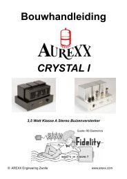
The producers: Guido Tent (L) and <strong>Menno</strong> <strong>van</strong> <strong>der</strong> <strong>Veen</strong> (R)<br />
For more information:<br />
www.menno<strong>van</strong><strong>der</strong>veen.nl<br />
www.tentlabs.com
7- Appendix: Comparing C-<strong>MEC</strong>-C with C-R-C filters<br />
Suppose the mains frequency f = 50 Hz and a current demand equals I. Then the voltage<br />
ripple V a (see figure 1, peak to peak value) is given by:<br />
V a<br />
I<br />
2 . n. f . C 1<br />
where n=1 for single and n-2 for double sided rectification (like in figure 1).<br />
Suppose the inductance of the <strong>MEC</strong> equals L, then the peak to peak ripple voltage V b<br />
over C2 is given by the next formula:<br />
0.7<br />
V b<br />
4.<br />
π 2<br />
.<br />
I<br />
2 3 . f 3 . L. C .<br />
1<br />
C 2<br />
Our measurements showed that V b is a factor 1000 smaller than V a . When we calculate<br />
V a /V b , we find (for n=2):<br />
V a<br />
4. π 2 . 2. f 2 . C 2<br />
L<br />
V b<br />
0.7<br />
Using C 1 =C 2 = 47 µF and f = 50Hz, we find L = 78 H.<br />
Now imagine, we remove our <strong>MEC</strong> and replace it by a standard resistor R, and we wish<br />
the same ripple rejection as in the example above. How large should R be, how much<br />
heat in R and how much voltage drop would occur Now we use a so called C-R-C<br />
network, and there the ripple ratio is given by:<br />
V a<br />
V b R<br />
2. π 2 . f . R.<br />
C 2<br />
,<br />
0.7<br />
Lets apply V a /V b,R = 1000, then we find R = 15,1 kOhm. At 50 mA the voltage drop over<br />
R equals 755 V and the heat inside R is 38 Watt.<br />
Must we say more The <strong>MEC</strong> looses 10 V maximum with an internal heat less than 1<br />
Watt; far more better than the C-R-C solution as discussed above, which proves our<br />
case.