THE VANDERVEEN MC-10 - Menno van der Veen
THE VANDERVEEN MC-10 - Menno van der Veen
THE VANDERVEEN MC-10 - Menno van der Veen

You also want an ePaper? Increase the reach of your titles
YUMPU automatically turns print PDFs into web optimized ePapers that Google loves.
<strong>THE</strong> <strong>VANDERVEEN</strong> <strong>MC</strong>-<strong>10</strong><br />
The high-end stepup transformer for moving coil cartridges.<br />
The <strong>MC</strong>-<strong>10</strong> transforms the small output voltages of a moving coil cartridge into a <strong>10</strong> times<br />
larger voltage for direct connection to the MM input of a pre amplifier. The frequency range is<br />
very wide, eminent core material with inaudible low granulation distortion (Barkhausen noise),<br />
linear phase and differential phase, critical damping of the <strong>MC</strong> cartridge, large magnetic<br />
headroom with inaudible low frequency distortion, easy mounting for asymmetrical (RCA) and<br />
symmetrical (XLR-3) inputs and outputs, precise adjustment to any <strong>MC</strong> cartridge by means of<br />
three external components, …<br />
Introduction<br />
Gramophone discs surely have not left the high-end scene. Their quality is still unbeaten and<br />
sound lovers are willing to spend fast amounts of money for high quality turntables and<br />
cartridges. My new Van<strong>der</strong>veen <strong>MC</strong>-<strong>10</strong> stepup transformer is designed for these quality<br />
lovers, for those men and women who wish to enjoy the goodies of the disc. They focus on<br />
pure quality of sound, deep emotions and nostalgia. What is wrong with the latest<br />
For many years the quality of audio reproduction has been my main topic of research. One of<br />
the results of this research and study has been my Van<strong>der</strong>veen toroidal output transformer<br />
for valve amplifiers. With these transformers I was able to fundamentally change a warm<br />
sounding valve amp into a broad bandwidth undistorted high quality product. It has taken me<br />
more than 40 years to do this job and I am still not ready (will I ever be). The new<br />
Van<strong>der</strong>veen <strong>MC</strong>-<strong>10</strong> leans on this fast experience. Now I have decided to focus on the other<br />
side of the valuable high-end chain. Not a new study about amps or loudspeakers, but<br />
attention to the most sensitive part of the sound system: the moving coil cartridge. The <strong>MC</strong>-<br />
<strong>10</strong> has been intended to amplify its small voltages to reasonable values. This time I don’t<br />
speak about Watts, I deal with micro Volts!<br />
Inside a moving coil (<strong>MC</strong>) cartridge a coil is swinging in a stationary magnetic field. Moving<br />
Magnet (MM) cartridges have, as their name says, a moving magnet with a stationary coil.<br />
The ad<strong>van</strong>tages of <strong>MC</strong> versus MM are a lower moving mass and less resonances above 20<br />
kHz. However, the main disad<strong>van</strong>tage of <strong>MC</strong> is its very low output voltage. At 1 kHz and 2.5<br />
cm/s cutting speed they generate about 0.1 to 0.4 mV. This output voltage is too small for<br />
direct input to a standard MM pre amp with its RIAA correction. The standardized input<br />
sensitivity for MM equals 4.7 mV and normal <strong>MC</strong> cartridges are not able to deliver such<br />
voltages. There are two solutions to solve this problem: a) Take an active pre amp (with<br />
valves or semiconductors or IC’s) with an amplification factor of <strong>10</strong> –or- b) apply a stepup<br />
transformer between the <strong>MC</strong> cartridge and the MM input. My experience has taught me that<br />
passive solutions (a transformer) mostly sound superior to active solutions (pre-pre amp). So<br />
I decided to follow the transformer trail. The new Van<strong>der</strong>veen <strong>MC</strong>-<strong>10</strong> magnifies the <strong>MC</strong><br />
voltages with a factor of <strong>10</strong>. Also the optimal load to the <strong>MC</strong> cartridge can be adjusted easily.<br />
On exploration tour<br />
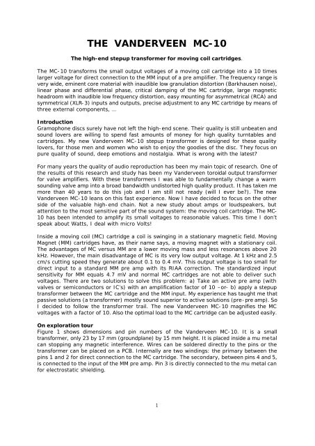
Figure 1 shows dimensions and pin numbers of the Van<strong>der</strong>veen <strong>MC</strong>-<strong>10</strong>. It is a small<br />
transformer, only 23 by 17 mm (groundplane) by 15 mm height. It is placed inside a mu metal<br />
can stopping any magnetic interference. Wires can be sol<strong>der</strong>ed directly to the pins or the<br />
transformer can be placed on a PCB. Internally are two windings: the primary between the<br />
pins 1 and 2 for direct connection to the <strong>MC</strong> cartridge. The secondary, between pins 4 and 5,<br />
is connected to the input of the MM pre amp. Pin 3 is directly connected to the mu metal can<br />
for electrostatic shielding.<br />
1
Dimensions and pin connections of <strong>VANDERVEEN</strong> <strong>MC</strong>-<strong>10</strong><br />
1<br />
5<br />
HT=15<br />
5x2,5<br />
D=0,6<br />
PRIM<br />
SEC<br />
17<br />
1 2 3<br />
pin-side<br />
5<br />
4<br />
2<br />
4<br />
3<br />
1 & 5 are equal phase<br />
3 connected to mu-metal case mm<br />
23<br />
12,5<br />
Figure 1: pins and numbers plus dimensions of the <strong>MC</strong>-<strong>10</strong><br />
Figure 2 looks inside the transformer and the <strong>MC</strong> cartridge and the input section of the MM<br />
pre amp. The <strong>MC</strong> cartridge on the left side is represented by a voltage source with the wire<br />
resistance R DC of the moving coil in series. The input section of the MM pre amp is<br />
represented by its input impedance, which forms a load to the secondary of the stepup<br />
transformer. This input impedance consists of R L (mostly 47 kOhm) and the input capacitance<br />
C L of the pre amp plus the interlink (close to <strong>10</strong>0 pF). Central in figure 2 is the <strong>MC</strong>-<strong>10</strong> with its<br />
windings N p and N s , wire resistances R ip and R is plus the inductances L p and L s . The leakage<br />
inductance L ss plus the internal capacitors (actually between the turns and windings) C is and<br />
C ps together determine the high frequency behavior of the stepup transformer. In red, three<br />
components have been drawn: R in , R C and C C . With these external components a very precise<br />
adjustment for optimal load and frequency transfer from any moving coil cartridge to the MM<br />
pre amp input can be realized.<br />
moving coil<br />
pick up<br />
<strong>VANDERVEEN</strong> <strong>MC</strong>-<strong>10</strong><br />
amplifiers<br />
MM - input<br />
V mc<br />
R dc<br />
1<br />
2<br />
R ip<br />
Cps<br />
N p N s<br />
L<br />
R ss is<br />
L p L s C is<br />
R in<br />
Figure 2: equivalent scheme of the total <strong>MC</strong> chain<br />
5<br />
4<br />
R c<br />
Cc<br />
R L<br />
C L<br />
In the next chapters the following issues will be discussed: 1) how to connect the <strong>MC</strong>-<strong>10</strong>, 2)<br />
optimal loading of the <strong>MC</strong> cartridges, 3) high frequency adjustments, 4) specifications plus<br />
additional info and hints.<br />
How to connect the <strong>MC</strong>-<strong>10</strong><br />
The <strong>MC</strong>-<strong>10</strong> can be placed inside the console of the turntable, or in a separate metal box, or<br />
(if place is available) inside the MM pre amp. In all cases the methods of mounting are equal.<br />
Therefore I take as example the separate metal box with two <strong>MC</strong>-<strong>10</strong> transformers (for left and<br />
right channel).<br />
2
This box is placed between the turntable and the MM pre amp and connected with high<br />
quality interlinks. Two methods for connecting are possible: an asymmetric connection with<br />
RCA-cinch connectors or a symmetric connection with XLR-3 connectors. The asymmetric<br />
connection is the most common and therefore will be discussed now.<br />
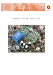
Asymmetric connection<br />
Figure 3 shows the metal box, bottom view, with 4 high quality RCA panel sockets. Also a<br />
grounding screw has been included for grounding of the turntable to the metal box. With<br />
silicon glue the transformers can be glued to the metal box (easy to remove). Use high quality<br />
mounting wire (silver wire is an excellent choice) and sol<strong>der</strong> the wires (with silver sol<strong>der</strong>). The<br />
resistors R in and R C plus the capacitor C C have not been drawn yet. They will be discussed<br />
later on.<br />
1 2 3<br />
pin-side<br />
5<br />
4<br />
1 2 3<br />
pin-side<br />
5<br />
4<br />
Figure 3: asymmetric connection<br />
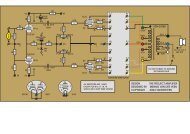
Figure 4 shows the schematics of this asymmetric connection. The transformer pins 2 and 3<br />
and 4 are connected to each other and tight to the ground of the metal case. The <strong>MC</strong> signal<br />
goes to pin 1 directly, while the output signal to the MM input comes from pin 5.<br />
moving coil<br />
pick up<br />
<strong>VANDERVEEN</strong> <strong>MC</strong>-<strong>10</strong><br />
amplifiers<br />
MM - input<br />
V mc<br />
R dc<br />
R in<br />
1<br />
2<br />
R ip<br />
Cps<br />
N p<br />
L p<br />
N s<br />
L s<br />
R is<br />
L ss<br />
C is<br />
5<br />
4<br />
R c<br />
Cc<br />
R L<br />
C L<br />
ground<br />
turntable<br />
3<br />
ground<br />
Figure 4: asymmetric connection scheme<br />
3
Balanced or symmetric connection<br />
I will start with a warning: all wires inside and outside the turntable, starting at the <strong>MC</strong><br />
cartridge, up to the <strong>MC</strong>-<strong>10</strong> input, should be high quality electrostatic shielded. This shielding<br />
should be firmly connected to the turntable ground. The signal wires from <strong>MC</strong> cartridge to <strong>MC</strong>-<br />
<strong>10</strong> should be balanced and shielded and correctly connected to a XLR-3M plug. Suppose<br />
above is not the case, then stop using this balanced connection scheme. Nasty humming will<br />
be the reward and that is not my or your aim. This hum is very difficult to remove. Only<br />
perfect electrostatic shielding, all along the signal lines, is able to stop it.<br />
Figure 5 again shows the metal box. Two XLR-3F audio panel sockets have been drawn at the<br />
input side, while the output has two RCA-sockets, assuming that the MM pre amp is<br />
asymmetric. For symmetric MM input, the correct method of connecting will be discussed later<br />
on.<br />
3 3<br />
1 1<br />
2 2<br />
1 2 3<br />
pin-side<br />
5<br />
4<br />
1 2 3<br />
pin-side<br />
5<br />
4<br />
Figure 5: balanced connection<br />
The convention for balanced connections is as follows: pin-1 of XLR-3F is to ground, pin-2 of<br />
XLR-3F comes from the in-phase side of the <strong>MC</strong> cartridge, pin-3 comes from the out-of-phase<br />
side of the <strong>MC</strong> cartridge. The numbers are clearly indicated on the plugs and sockets,<br />
assuming they are of good quality. Neutrix Gold is an example of such high quality plugs and<br />
sockets.<br />
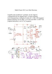
Figure 5 shows the internal wiring in the metal box. Again the components R in and R C and C C<br />
have not been drawn. They will be discussed later on. Figure 6 shows the connection scheme.<br />
There is clearly visible that <strong>MC</strong>-<strong>10</strong>-pin-1 is connected to the in-phase signal of the cartridge,<br />
while <strong>MC</strong>-<strong>10</strong>-pin-2 is connected to the out-of-phase <strong>MC</strong> cartridge signal. This means that the<br />
cartridge is directly connected over the primary and is floating. Shielding and grounding do not<br />
interfere with the signal flow. This is one of the reasons why professionals apply balanced<br />
connections for high quality audio.<br />
4
moving coil<br />
pick up<br />
<strong>VANDERVEEN</strong> <strong>MC</strong>-<strong>10</strong><br />
amplifiers<br />
MM - input<br />
V mc<br />
R dc<br />
R in<br />
1<br />
2<br />
R ip<br />
Cps<br />
N p N s<br />
L<br />
R ss is<br />
L p L s C is<br />
5<br />
4<br />
R c<br />
Cc<br />
R L<br />
C L<br />
ground<br />
turntable<br />
3<br />
ground<br />
Figure 6: symmetric connection scheme<br />
Suppose your MM input at the pre amp has a balanced socket as well. How to proceed Then<br />
<strong>MC</strong>-<strong>10</strong>-pin-4 should go to panel plug XLR-3M-pin-3; <strong>MC</strong>-<strong>10</strong>-pin-5 should go to XLR-3M-pin-2<br />
and the grounding plus <strong>MC</strong>-<strong>10</strong>-pin-3 should go to XLR-3M-pin-1. If these lines create<br />
dizziness, then make a small drawing as I did in figure 5; that surely will help.<br />
Optimal electrical load of the <strong>MC</strong> cartridge<br />
Each <strong>MC</strong> cartridge needs an electrical load to prevent high frequency resonances (ringing).<br />
These resonances are un<strong>der</strong>standable when we realize that a <strong>MC</strong> cartridge is a mass-spring<br />
system, which resonates per definition. These resonances should be damped (with Q between<br />
.5 and .7). Therefore the manufacturer of the cartridge specifies an optimal electrical load<br />
impedance Z L . In this case the extra resistor R in plus the input impedance at the primary side<br />
of the <strong>MC</strong>-<strong>10</strong> have to fulfill this job.<br />
Together with the input impedance (R L and C L ) of the MM pre amp, the <strong>MC</strong>-<strong>10</strong> transformer<br />
creates a certain load to the <strong>MC</strong> cartridge. This load equals 344 Ohm. Suppose that this is<br />
exactly the optimal load as advised by the manufacturer, then no further actions should be<br />
taken. But life is hard, such a chance is seldom. So lets stick to reality and accept that the<br />
manufacturer advises a smaller electrical load than the 344 Ohm given. In case the<br />
manufacturer of the <strong>MC</strong> cartridge advises a larger value than 344 Ohm, then please do not<br />
use my <strong>MC</strong>-<strong>10</strong> transformer; it will not be optimal for such specific cartridges.<br />
As an example, I now discuss a cartridge with an optimal load Z L = 150 Ohm. To realize this<br />
value, the extra resistor R in should be inserted. Its value can be calculated by the following<br />
formula: R in = (344 * 150) / (344 – 150) = 267 Ohm (take the E12 standard value of 270<br />
Ohm). Another example: suppose the optimal value of Z L should be equal to 67 Ohm. Then R in<br />
= (344 * 67) / (344 – 67) = 83 Ohm (take the E12 standard value of 82 Ohm).<br />
Because every specific <strong>MC</strong> cartridge has its own optimal Z L , it is impossible to deliver all<br />
possible values of R in with the <strong>MC</strong>-<strong>10</strong>. If you need them, buy resistors from the E12 range with<br />
values closest to the values calculated. Metal film resistors of ¼ W power handling are fine,<br />
high precision wire wound (non-inductive) is better for noise reasons. Table 7 gives more<br />
values for R in to support your calculations.<br />
Summary: with one external resistor R in optimal loading of the <strong>MC</strong> cartridge can be realized<br />
very precisely. In agreement with the specifications of the <strong>MC</strong> manufacturer an optimal<br />
electrical load prevents high frequency resonance above 20kHz.<br />
5
Z L R in R in according to E12<br />
344 Infinite place no resistor<br />
300 2345 2k2<br />
250 915 1k2 and 3k9 in parallel = 918<br />
200 478 470<br />
150 267 270<br />
<strong>10</strong>0 141 220 and 390 in parallel = 141<br />
50 58,5 56 + 2,7 in series<br />
30 32,9 33<br />
20 21,2 22<br />
<strong>10</strong> <strong>10</strong>,3 15 and 33 in parallel = <strong>10</strong>,3<br />
[Ohm] [Ohm] [Ohm]<br />
Table 7: Examples of various R in values related to Z L<br />
Where to place R in: directly between pins 1 and 2 of the <strong>MC</strong>-<strong>10</strong> with the shortest leads<br />
possible. See figure 8 for more details.<br />
R<br />
in<br />
R<br />
in<br />
1 2 3<br />
pin-side<br />
5<br />
4<br />
1 2 3<br />
pin-side<br />
5<br />
4<br />
R<br />
C<br />
C C C C<br />
R<br />
C<br />
Figure 8: the mounting of R in , R C and C C<br />
6
High frequency adjustments of the <strong>MC</strong>-<strong>10</strong><br />
Inside the <strong>MC</strong>-<strong>10</strong> various resistors, inductors and capacitors are present. In physics language<br />
this means that electrical resonances might occur. The <strong>MC</strong>-<strong>10</strong> is designed in such a manner<br />
that un<strong>der</strong> most conditions these resonances are well damped. However, when the wire<br />
resistance R DC of the coil of the <strong>MC</strong> cartridge is smaller than 20 Ohm, an external correction is<br />
needed for. Now R DC is the critical factor. Refer to the manufacturer specifications of your <strong>MC</strong><br />
cartridge to find its value.<br />
It is mandatory to remove high frequency resonances inside the transformer. Suppose you<br />
don’t, then at high frequencies the amplitude will get larger and will last longer. This effect is<br />
described in literature as “ringing”. When listening to it the character of the sound will be too<br />
fresh, too sharp and thin. Probably you will get tired of listening to it. An extra effect is a<br />
strong deviation in the time behavior of the signal. Phase deviations will occur. Even worse is<br />
severe differential phase distortion. The latest tells about a sound complex (a sound burst<br />
comprising many frequencies, like the sound of a drum kit) with its envelope. When differential<br />
phase distortion occurs, low frequencies are delayed more than high frequencies. As a result<br />
the envelope of the sound burst is distorted. Our hearing mechanism not only detects<br />
frequencies and times of arrival, but also detects the nature of the envelope (this is done by<br />
the a-linear amplitude transfer of the ear, in fact by a distortion mechanism inside the ear).<br />
As a consequence, the differential phase distortion should be very small, and therefore high<br />
frequency resonances should be well damped.<br />
To solve all these nasty issues, a very simple activity should be performed: add R C and C C .<br />
The resistor R C and capacitor C C are placed in series, directly between the pins 4 and 5 of the<br />
<strong>MC</strong>-<strong>10</strong> transformer, with shorted wires possible. See figure 8. Use metal film ¼ W resistors<br />
(wire wound is disad<strong>van</strong>tageous in this case). For the capacitor C C : any working voltage is<br />
right; Styroflex is fine, Mica is better.<br />
Table 9 shows values of R C and C C for cartridges with R DC smaller than 20 Ohm. Please notice<br />
that there is a difference now between unbalanced and balanced use of the <strong>MC</strong>-<strong>10</strong><br />
transformer. The reason why is the different influence of C ps for both connection schemes. No<br />
further formulas are given because the calculation of R C and C C is rather complex. Their values<br />
are based on minimal phase distortion, which is a different goal than broadest bandwidth.<br />
Listening tests have shown that phase distortion is well related to listening tiredness. So I<br />
have aimed at minimal phase distortion. In practice: select/buy R C and C C values from the E12<br />
range closest to those given in table 9.<br />
R DC R C unbal. C C unbal. f -3H unbal. R C bal. C C bal. f -3H bal.<br />
3 15k 150 70 3k8 330 90<br />
5 18k 120 70 4k7 270 90<br />
<strong>10</strong> 18k <strong>10</strong>0 70 6k8 180 <strong>10</strong>0<br />
15 47k 47 60 15k <strong>10</strong>0 ><strong>10</strong>0<br />
20 None none 50 22k 56 ><strong>10</strong>0<br />
21 None none 50 none none <strong>10</strong>0<br />
[Ohm] [Ohm] [pF] [kHz] [Ohm] [pF] [kHz]<br />
Table 9: high frequency <strong>MC</strong>-<strong>10</strong> correction with R C and C C for R DC < 20 Ohm<br />
7
Specifications of the <strong>MC</strong>-<strong>10</strong><br />
During manufacturing, small deviations always occur. Table <strong>10</strong> shows the values of the<br />
important quantities inside the <strong>MC</strong>-<strong>10</strong> transformer plus maximum allowable (accepted)<br />
deviations. See figure 2 for details of the meaning of any quantity.<br />
<strong>MC</strong>-<strong>10</strong> value deviation unit<br />
N s / N p 12,0 +/- 1 % [ - ]<br />
R ip 11,0 +/- 5 % [Ohm]<br />
L P 1,0 +/- 4 % [H]<br />
R is 1k62 +/- 1 % [Ohm]<br />
C is 202 +/- 7 % [pF]<br />
C ps-eff 427 +/- 9 % [pF]<br />
L ss 5.9 +/- 15 % [mH]<br />
V p,max <strong>10</strong>0 20Hz @ 1% THD [mVrms]<br />
R C & C C table 9 table 9 table 9<br />
R L & C L 47k//<strong>10</strong>0p Standard MM-input [Ohm] & [F]<br />
Table <strong>10</strong>: <strong>MC</strong>-<strong>10</strong> specifications<br />
Those who love maths will be very happy with these specs. Later on I will tell more about how<br />
to construct and calculate the transfer formulas.<br />
The deviations allowed in L ss , C is and C ps seem to be remarkably large. Their values have been<br />
measured in a very specific manner, which leads to these deviations. Un<strong>der</strong> various conditions<br />
the internal resonance frequencies inside the transformer are measured. These frequency<br />
values are subtracted to calculate the leakage inductance and internal capacitors. Then per<br />
definition each deviation in frequency results in an enlarged deviation in final inductance or<br />
capacitance value. In spite of this mathematical disad<strong>van</strong>tage, I will stick to this method. Its<br />
results are amazingly precise in predicting the actual frequency transfer of the <strong>MC</strong>-<strong>10</strong><br />
transformer.<br />
The primary inductance L P is measured at 80 mV pp @ 1 kHz. When enlarging this measurement<br />
voltage up to 8 V pp , the value of L P hardly changes. With larger voltages than 8 V pp , core<br />
saturation might occur, blurring the measurement. Also notice the very important specification<br />
V p,max . It tells about the large magnetic headroom inside this small transformer. Overloading of<br />
this transformer at the lowest frequencies is virtually impossible, resulting in unhearable low<br />
frequency distortion.<br />
The coupling capacitor C ps between primary and secondary windings is not totally active in<br />
the frequency domain. The part that influences the frequency transfer is given by C ps,eff . In<br />
the balanced connection scheme only C is is active. In unbalanced connection C is plus C ps,eff are<br />
active and their values should be summed to find the total capacitance at the secondary<br />
side. This also explains the difference in –3dB high frequency range (indicated by f -3H )<br />
between unbalanced and balanced connection. See table 11 for more details.<br />
8
R DC f -3L f -3H unbal. f -3H bal.<br />
<strong>10</strong> 3 70 <strong>10</strong>0<br />
20 4 50 ><strong>10</strong>0<br />
30 5 40 90<br />
40 7 38 90<br />
50 8 32 80<br />
60 9 27 70<br />
70 <strong>10</strong> 25 60<br />
80 11 20 50<br />
90 12 19 50<br />
[Ohm] [Hz] [kHz] [kHz]<br />
Table 11: -3dB frequency range of the <strong>MC</strong>-<strong>10</strong> as function of R DC<br />
It is not so difficult to create the frequency transfer functions of the <strong>MC</strong>-<strong>10</strong> transformer,<br />
when using the following hints. Cut the total transfer in three separate parts. The low<br />
frequency part only consi<strong>der</strong>s the resistances and L p , where the secondary side resistors are<br />
transformed to the primary side by factor 12 -2 . The midfrequency part deals with an ideal<br />
transformer and resistances only. The high frequency section again uses an ideal transformer,<br />
omits L P , but now takes the capacitors and the leakage inductance into account.<br />
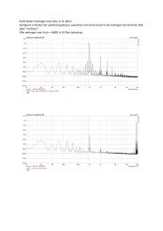
As an example figure 12 shows the calculated (and measured) transfer function of the <strong>MC</strong>-<strong>10</strong><br />
for the R DC = 50 Ohm case.<br />
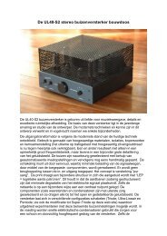
Figure 13 shows phase and differential phase distortions. Remarkably low is the differential<br />
phase distortion up to 30 kHz (smaller than 1 degree), which is a very fine result.<br />
transfer [dB]<br />
25<br />
24<br />
23<br />
22<br />
21<br />
20<br />
19<br />
18<br />
17<br />
16<br />
15<br />
Van<strong>der</strong>veen <strong>MC</strong>-<strong>10</strong><br />
<strong>10</strong> <strong>10</strong>0 1 <strong>10</strong> 3 1 <strong>10</strong> 4 1 <strong>10</strong> 5<br />
frequency [Hz]<br />
Figure 12: transfer characteristic of the <strong>MC</strong>-<strong>10</strong>, R DC = 50 Ohm,<br />
balanced connection.<br />
9
90<br />
<strong>MC</strong>-<strong>10</strong> : phase (RED) ; dif.phase (BLUE)<br />
60<br />
degrees<br />
30<br />
30<br />
0<br />
60<br />
90<br />
<strong>10</strong> <strong>10</strong>0 1 <strong>10</strong> 3 1 <strong>10</strong> 4 1 <strong>10</strong> 5<br />
frequency [Hz]<br />
Figure 13: phase characteristics of the <strong>MC</strong>-<strong>10</strong> for R DC = 50 Ohm,<br />
balanced connection<br />
Final remarks<br />
It might surprise the rea<strong>der</strong> that so many details are told about such a small moving coil<br />
stepup transformer. The answer is: physics and electronics deliver many details, which should<br />
not be omitted. Some products are only described with unclear words. Then you only can<br />
hope that these words tell the whole story. Mostly this is not the case and a real<br />
disappointment is the net result. Therefore, tell the whole story, and everyone at his/her level<br />
will find the important clues. “Maths-type” persons will grab their calculator. “Measurement is<br />
knowing” persons will spend evenings behind the oscilloscope, while “listeners” now will<br />
un<strong>der</strong>stand why the soundstage is open without getting tired. I have always aimed at<br />
delivering much information about my toroidal transformers. I have written books about them<br />
plus scientific papers. The net results are that my clients know very much about my products.<br />
Exactly the same happens here with the <strong>MC</strong>-<strong>10</strong>.<br />
However, this also means that when I formulate a warning about possible hum, this warning<br />
should not be forgotten. It is true that the balanced connection only functions well un<strong>der</strong><br />
electrostatic shielded conditions. If the shielding is incomplete, 50 or 60 Hz interference surely<br />
will cause a nasty humming sound stage.<br />
Ground loops can cause hum as well, where the magnetic leakage of a near by EI-transformer<br />
create problems. This issue is very important. I will not go into further details now. My<br />
website is patient; maybe in the near future an extra article will follow.<br />
Now lets deal with the subjective side of the matter. Before the introduction of the <strong>MC</strong>-<strong>10</strong><br />
transformer, I sent samples all over the world, asking for scientific and listening opinions.<br />
Many remarks were the result and they were dealt with. What stroke me in all the subjective<br />
comments was the following: “the richness in details is extreme”. For me as designer this<br />
simply means that I have selected the right core material and high frequency adjustments.<br />
“After some hours the <strong>MC</strong>-<strong>10</strong> comes to rest and starts to blossom”. Again this is<br />
un<strong>der</strong>standable. During production all the specs of the <strong>MC</strong>-<strong>10</strong> are checked. These<br />
measurements can leave a residual magnetic field inside the core. After some listening hours<br />
in actual application, the mean magnetic flux density ‘swings’ back to zero, where distortion<br />
and Barkhausen noise are lowest. As you see, science and listening are very closely<br />
connected here. I really hope that this small <strong>MC</strong>-<strong>10</strong> transformer will deliver you pure<br />
enjoyment.<br />
The Netherlands, Zwolle,<br />
March 16 2004<br />
ir. <strong>Menno</strong> <strong>van</strong> <strong>der</strong> <strong>Veen</strong><br />
ir. bureau Van<strong>der</strong>veen<br />
<strong>10</strong>