THE VANDERVEEN MC-10 - Menno van der Veen
THE VANDERVEEN MC-10 - Menno van der Veen
THE VANDERVEEN MC-10 - Menno van der Veen

You also want an ePaper? Increase the reach of your titles
YUMPU automatically turns print PDFs into web optimized ePapers that Google loves.
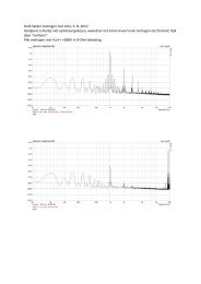
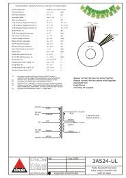
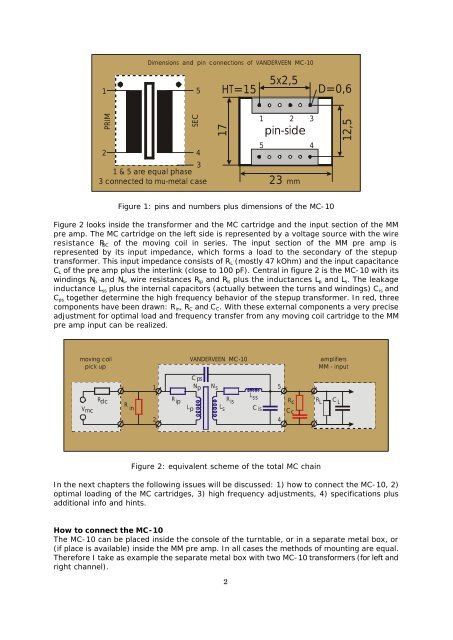
Dimensions and pin connections of <strong>VANDERVEEN</strong> <strong>MC</strong>-<strong>10</strong><br />
1<br />
5<br />
HT=15<br />
5x2,5<br />
D=0,6<br />
PRIM<br />
SEC<br />
17<br />
1 2 3<br />
pin-side<br />
5<br />
4<br />
2<br />
4<br />
3<br />
1 & 5 are equal phase<br />
3 connected to mu-metal case mm<br />
23<br />
12,5<br />
Figure 1: pins and numbers plus dimensions of the <strong>MC</strong>-<strong>10</strong><br />
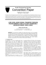
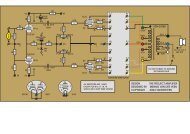
Figure 2 looks inside the transformer and the <strong>MC</strong> cartridge and the input section of the MM<br />
pre amp. The <strong>MC</strong> cartridge on the left side is represented by a voltage source with the wire<br />
resistance R DC of the moving coil in series. The input section of the MM pre amp is<br />
represented by its input impedance, which forms a load to the secondary of the stepup<br />
transformer. This input impedance consists of R L (mostly 47 kOhm) and the input capacitance<br />
C L of the pre amp plus the interlink (close to <strong>10</strong>0 pF). Central in figure 2 is the <strong>MC</strong>-<strong>10</strong> with its<br />
windings N p and N s , wire resistances R ip and R is plus the inductances L p and L s . The leakage<br />
inductance L ss plus the internal capacitors (actually between the turns and windings) C is and<br />
C ps together determine the high frequency behavior of the stepup transformer. In red, three<br />
components have been drawn: R in , R C and C C . With these external components a very precise<br />
adjustment for optimal load and frequency transfer from any moving coil cartridge to the MM<br />
pre amp input can be realized.<br />
moving coil<br />
pick up<br />
<strong>VANDERVEEN</strong> <strong>MC</strong>-<strong>10</strong><br />
amplifiers<br />
MM - input<br />
V mc<br />
R dc<br />
1<br />
2<br />
R ip<br />
Cps<br />
N p N s<br />
L<br />
R ss is<br />
L p L s C is<br />
R in<br />
Figure 2: equivalent scheme of the total <strong>MC</strong> chain<br />
5<br />
4<br />
R c<br />
Cc<br />
R L<br />
C L<br />
In the next chapters the following issues will be discussed: 1) how to connect the <strong>MC</strong>-<strong>10</strong>, 2)<br />
optimal loading of the <strong>MC</strong> cartridges, 3) high frequency adjustments, 4) specifications plus<br />
additional info and hints.<br />
How to connect the <strong>MC</strong>-<strong>10</strong><br />
The <strong>MC</strong>-<strong>10</strong> can be placed inside the console of the turntable, or in a separate metal box, or<br />
(if place is available) inside the MM pre amp. In all cases the methods of mounting are equal.<br />
Therefore I take as example the separate metal box with two <strong>MC</strong>-<strong>10</strong> transformers (for left and<br />
right channel).<br />
2