THE VANDERVEEN MC-10 - Menno van der Veen
THE VANDERVEEN MC-10 - Menno van der Veen
THE VANDERVEEN MC-10 - Menno van der Veen

You also want an ePaper? Increase the reach of your titles
YUMPU automatically turns print PDFs into web optimized ePapers that Google loves.
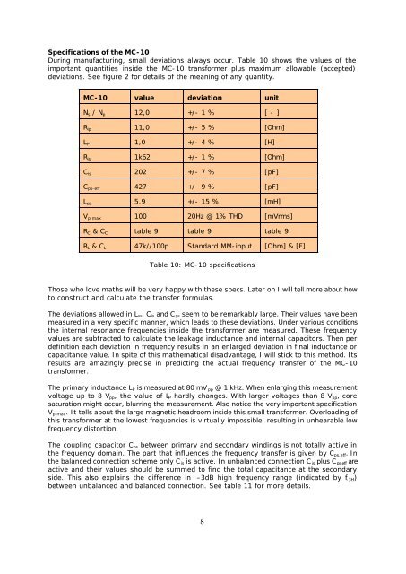
Specifications of the <strong>MC</strong>-<strong>10</strong><br />
During manufacturing, small deviations always occur. Table <strong>10</strong> shows the values of the<br />
important quantities inside the <strong>MC</strong>-<strong>10</strong> transformer plus maximum allowable (accepted)<br />
deviations. See figure 2 for details of the meaning of any quantity.<br />
<strong>MC</strong>-<strong>10</strong> value deviation unit<br />
N s / N p 12,0 +/- 1 % [ - ]<br />
R ip 11,0 +/- 5 % [Ohm]<br />
L P 1,0 +/- 4 % [H]<br />
R is 1k62 +/- 1 % [Ohm]<br />
C is 202 +/- 7 % [pF]<br />
C ps-eff 427 +/- 9 % [pF]<br />
L ss 5.9 +/- 15 % [mH]<br />
V p,max <strong>10</strong>0 20Hz @ 1% THD [mVrms]<br />
R C & C C table 9 table 9 table 9<br />
R L & C L 47k//<strong>10</strong>0p Standard MM-input [Ohm] & [F]<br />
Table <strong>10</strong>: <strong>MC</strong>-<strong>10</strong> specifications<br />
Those who love maths will be very happy with these specs. Later on I will tell more about how<br />
to construct and calculate the transfer formulas.<br />
The deviations allowed in L ss , C is and C ps seem to be remarkably large. Their values have been<br />
measured in a very specific manner, which leads to these deviations. Un<strong>der</strong> various conditions<br />
the internal resonance frequencies inside the transformer are measured. These frequency<br />
values are subtracted to calculate the leakage inductance and internal capacitors. Then per<br />
definition each deviation in frequency results in an enlarged deviation in final inductance or<br />
capacitance value. In spite of this mathematical disad<strong>van</strong>tage, I will stick to this method. Its<br />
results are amazingly precise in predicting the actual frequency transfer of the <strong>MC</strong>-<strong>10</strong><br />
transformer.<br />
The primary inductance L P is measured at 80 mV pp @ 1 kHz. When enlarging this measurement<br />
voltage up to 8 V pp , the value of L P hardly changes. With larger voltages than 8 V pp , core<br />
saturation might occur, blurring the measurement. Also notice the very important specification<br />
V p,max . It tells about the large magnetic headroom inside this small transformer. Overloading of<br />
this transformer at the lowest frequencies is virtually impossible, resulting in unhearable low<br />
frequency distortion.<br />
The coupling capacitor C ps between primary and secondary windings is not totally active in<br />
the frequency domain. The part that influences the frequency transfer is given by C ps,eff . In<br />
the balanced connection scheme only C is is active. In unbalanced connection C is plus C ps,eff are<br />
active and their values should be summed to find the total capacitance at the secondary<br />
side. This also explains the difference in –3dB high frequency range (indicated by f -3H )<br />
between unbalanced and balanced connection. See table 11 for more details.<br />
8