THE VANDERVEEN MC-10 - Menno van der Veen
THE VANDERVEEN MC-10 - Menno van der Veen
THE VANDERVEEN MC-10 - Menno van der Veen

You also want an ePaper? Increase the reach of your titles
YUMPU automatically turns print PDFs into web optimized ePapers that Google loves.
High frequency adjustments of the <strong>MC</strong>-<strong>10</strong><br />
Inside the <strong>MC</strong>-<strong>10</strong> various resistors, inductors and capacitors are present. In physics language<br />
this means that electrical resonances might occur. The <strong>MC</strong>-<strong>10</strong> is designed in such a manner<br />
that un<strong>der</strong> most conditions these resonances are well damped. However, when the wire<br />
resistance R DC of the coil of the <strong>MC</strong> cartridge is smaller than 20 Ohm, an external correction is<br />
needed for. Now R DC is the critical factor. Refer to the manufacturer specifications of your <strong>MC</strong><br />
cartridge to find its value.<br />
It is mandatory to remove high frequency resonances inside the transformer. Suppose you<br />
don’t, then at high frequencies the amplitude will get larger and will last longer. This effect is<br />
described in literature as “ringing”. When listening to it the character of the sound will be too<br />
fresh, too sharp and thin. Probably you will get tired of listening to it. An extra effect is a<br />
strong deviation in the time behavior of the signal. Phase deviations will occur. Even worse is<br />
severe differential phase distortion. The latest tells about a sound complex (a sound burst<br />
comprising many frequencies, like the sound of a drum kit) with its envelope. When differential<br />
phase distortion occurs, low frequencies are delayed more than high frequencies. As a result<br />
the envelope of the sound burst is distorted. Our hearing mechanism not only detects<br />
frequencies and times of arrival, but also detects the nature of the envelope (this is done by<br />
the a-linear amplitude transfer of the ear, in fact by a distortion mechanism inside the ear).<br />
As a consequence, the differential phase distortion should be very small, and therefore high<br />
frequency resonances should be well damped.<br />
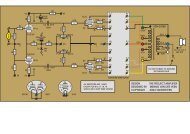
To solve all these nasty issues, a very simple activity should be performed: add R C and C C .<br />
The resistor R C and capacitor C C are placed in series, directly between the pins 4 and 5 of the<br />
<strong>MC</strong>-<strong>10</strong> transformer, with shorted wires possible. See figure 8. Use metal film ¼ W resistors<br />
(wire wound is disad<strong>van</strong>tageous in this case). For the capacitor C C : any working voltage is<br />
right; Styroflex is fine, Mica is better.<br />
Table 9 shows values of R C and C C for cartridges with R DC smaller than 20 Ohm. Please notice<br />
that there is a difference now between unbalanced and balanced use of the <strong>MC</strong>-<strong>10</strong><br />
transformer. The reason why is the different influence of C ps for both connection schemes. No<br />
further formulas are given because the calculation of R C and C C is rather complex. Their values<br />
are based on minimal phase distortion, which is a different goal than broadest bandwidth.<br />
Listening tests have shown that phase distortion is well related to listening tiredness. So I<br />
have aimed at minimal phase distortion. In practice: select/buy R C and C C values from the E12<br />
range closest to those given in table 9.<br />
R DC R C unbal. C C unbal. f -3H unbal. R C bal. C C bal. f -3H bal.<br />
3 15k 150 70 3k8 330 90<br />
5 18k 120 70 4k7 270 90<br />
<strong>10</strong> 18k <strong>10</strong>0 70 6k8 180 <strong>10</strong>0<br />
15 47k 47 60 15k <strong>10</strong>0 ><strong>10</strong>0<br />
20 None none 50 22k 56 ><strong>10</strong>0<br />
21 None none 50 none none <strong>10</strong>0<br />
[Ohm] [Ohm] [pF] [kHz] [Ohm] [pF] [kHz]<br />
Table 9: high frequency <strong>MC</strong>-<strong>10</strong> correction with R C and C C for R DC < 20 Ohm<br />
7