product installation instructions - Ron Francis Wiring
product installation instructions - Ron Francis Wiring
product installation instructions - Ron Francis Wiring

Create successful ePaper yourself
Turn your PDF publications into a flip-book with our unique Google optimized e-Paper software.
TELORVEK II<br />
TP-52<br />
TPI Fuel Injection Systems<br />
Page #1<br />
This wiring system is compatible with 1990 through 1992 GM 3.1 V6 tuned port engines. The system<br />
operates using the 1990 through 1992 Camaro engine control computer. GM has updated this computer<br />
1227730 a few times since 1990. Any one of the three computer numbers listed below can be used with<br />
this system. If you purchase a new computer through GM, the 16198262 computer will be supplied. New<br />
computers are not supplied with proms. One must be installed or the engine WILL fail to operate. These<br />
computers are also used in other GM vehicle model applications. If you have purchased your computer<br />
used, be sure it came from a 90-92 Camaro. If it came from another vehicle model, a new factory stock<br />
Camaro prom must be installed in the computer.<br />
1990-1992 GM Camaro Computer (ECM) #’s1227730 or 16196344 or 16198262
Page #2<br />
The Detail Zone fuel injection wire harnesses are “ALL” designed to follow the electronic circuitry of the<br />
vehicle your engine was removed from! Following this simple procedure allows our fuel injection harness<br />
customers to have their vehicles diagnosed by “ANY” GM dealer or reputable repair facility familiar with<br />
diagnosing fuel injection electronic systems.<br />
The Detail Zone does not re-engineer electronic circuitry that a vehicle manufacturer has spent millions of<br />
dollars on testing and designing. Our goal is to allow an “easy”, “neat”, “pain free” <strong>installation</strong> through<br />
quality <strong>installation</strong> <strong>instructions</strong> and a state of the art wiring kit.<br />
If your vehicle experiences starting or runability problems, 99% of the time<br />
it is some sort of mechanical, NOT A WIRING PROBLEM. Fuel injection engines still run similar to<br />
carbureted engines, the difference being that the engine computer receives “inputs” from various sensors<br />
throughout the engine. The computer then uses this information to calibrate fuel delivery and engine<br />
timing.<br />
Diagnosing a NO SPARK situation is the same on a computer controlled fuel injection engine as it is on a<br />
carbureted engine. Spark control, even though it may be done slightly different depending on engine year<br />
and make, is still essentially the same. A rotor is turned allowing spark to be provided to the plugs, the<br />
same as in a carbureted engine.<br />
Thank you for purchasing our <strong>product</strong>s!
Page #3<br />
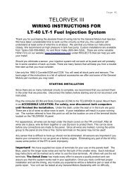
WIRING INSTRUCTIONS<br />
Thank you for purchasing the absolute finest of wiring kits for the General Motors fuel injection. We have<br />
taken considerable time to work out the circuitry so that you, the customer will understand at least some of<br />
what this is all about. We ask that you follow our <strong>instructions</strong> closely. We recommend a high pressure intank<br />
fuel pump. Custom <strong>installation</strong>s are available from Tanks, Inc. (phone # 320-558-6882) and Rock<br />
Valley (phone #800-344-1934). There are some valuable HOW -TO’s on our website<br />
(www.thedetailzone.com) under PROJECTS that can help you with your install.<br />
Should you eliminate a sensor, your injection system will not work at its peak and will probably be in some<br />
variation of back up mode. There are many factors that will keep you from a trouble free start up that you<br />
must consider.<br />
Use only the 1990-1992 Camaro ECM. It has three connectors not two as with older models. Also you<br />
will need a Prom and knock sensor that match the engine size. The back page of the <strong>instructions</strong> is a list<br />
of optional accessories we offer and some of the General Motors part numbers you may need.<br />
STARTING INSTALLATION<br />
Since there are so many individual circuits to complete, we recommend that you connect them in the order<br />
that we prescribe. Disconnect the battery before starting and do not reconnect until instructed.<br />
Plug in the computer (ECM) to the wires running from the TELORVEK II panel and mount them in an<br />
ACCESSIBLE LOCATION. For safety, now disconnect the ECM connectors until finished the<br />
<strong>installation</strong>. Under the dash, under the seat or in the trunk are good. There are a lot of wires so allow<br />
room to work. A poor <strong>installation</strong> will result in a poor running car. The number referred to from this point<br />
on will be the location on one of the terminal blocks located on the TELORVEK II panel.<br />
A four gang terminal block with four wires running to the computer connectors also must be<br />
mounted near the Telorvek panel. Wire connections to this terminal block will be addressed later<br />
in these <strong>installation</strong> <strong>instructions</strong>.<br />
For appearance, all wires can be fed through the center of the TPI unit itself. After all wires are in place,<br />
wire tie them together or use Zip loom to protect them. This can be done before any connections are<br />
made to the panel. Since all wires are marked, running the entire group to the panel at one time is fine.<br />
Some terminals on the panel will not be used!<br />
Any sensor that is difficult to hook-up should not be eliminated. All sensors are important if you desire your<br />
conversion to run as good as a factory engine. Eliminating any part of this kit WILL cause some portion of<br />
the EFI to work improperly.
Page #4<br />
WARNING!<br />
After the kit <strong>installation</strong> is complete and it is necessary to diagnose<br />
a starting or drive-ability problem, follow the procedures<br />
recommended in the shop manual. All voltage tests must be<br />
preformed using a HIGH impedance, digital voltmeter. DO NOT use<br />
a test light on this system! DAMAGE WILL BE DONE to the engine<br />
computer if a test light is used on this system.<br />
Important! W e have supplied three sizes of terminals for your use on the panels itself. The yellow, used<br />
for 10-12 gauge wire, Blue, used for 14-16 gauge wire and red for the bulk of the smaller wires. Each<br />
individual bag <strong>instructions</strong> will be marked as to when to use the yellow and blue terminals. All others will<br />
use the red terminals.<br />
The Detail Zone has made every effort to assure a quality <strong>product</strong> and can assure you that this system<br />
works well in your application. Once you have confirmed proper <strong>installation</strong> and set the timing, any trouble<br />
you experience will be a defective part or seat of the pants repair. Your unit can be tested at any General<br />
Motors Dealership with no difficulty.<br />
Bag #21 COOLANT TEMPERATURE SENSOR After attaching the plug to the sensor, run the two<br />
wires to the panel and connect the yellow wire to #43 and the black wire to #44. The sensor is located on<br />
the left side of the engine behind the original location of the A/C compressor clutch.<br />
Bag #22A MANIFOLD AIR TEMPERATURE SENSOR which is located under the plenum, on the<br />
right rear of the engine and has two wires. Plug in the sensor and run the black wire to #8 and the tan wire<br />
to #9.<br />
Bag #23A THROTTLE POSITION SENSOR Since there are many different physical shapes for<br />
these units, it is important that the model used is matched to your computer. Plug into the sensor located<br />
on the throttle body and run the black wire to #10, Dk Blue to #11 and gray to #12. No adjustment is<br />
required.<br />
Bag #24 KNOCK SENSOR WIRING is a single wire hookup to the knock sensor. This will inform the<br />
computer of detonation and readjust the timing accordingly. If your engine is not equipped, the sensor<br />
may be installed in the drain plug hole just above the oil pan on either side. Connect the plug to the<br />
sensor and run the Dark Blue wire to #13.<br />
Bag #25 OR 25A. ELECTRONIC SPARK TIMING (Distributor) & IGNITION, TACH. At this<br />
time connect the EST wiring to the distributor and run Black wire to #14, Tan wire to #15, Purple wire to<br />
#16 and White wire to #17. The distributor must be from the engine that the injection came from not an<br />
older model with vacuum advance. Depending on which type of distributor (internal or external coil) the<br />
correct ignition and tach connection have been supplied. Follow the <strong>instructions</strong> below for the type of<br />
distributor you have:<br />
INTERNAL COIL DISTRIBUTOR: The Orange wire (HEI DIST->4) plugs into the BAT connection on<br />
the distributor cap and using the yellow terminal connects to #4 on the Telorvek panel. The purple wire<br />
(HEI DIST->TACH) connects to the tach connection of the distributor cap and then run to the tach.<br />
EXTERNAL COIL DISTRIBUTOR: Plug the gray connector into the coil. Using the yellow terminal run<br />
the orange wire (COIL->4) to #4 on the Telorvek panel. The purple wire (COIL->TACH) runs to the tach.<br />
NOTE: External coil distributors must use the factory harness that connects the coil<br />
to the distributor. If needed it may be ordered direct from GM under part # 12048976.
Page #5<br />
Bag #26. ASSEMBLY LINE DATA LINK (ALDL) and SERVICE ENGINE LIGHT (Check<br />
Engine Light) The ALDL is the diagnostic link for computerized testing at your local GM dealer or a<br />
hand held scanner. We have supplied a Cover for the ALDL to dress up the appearance. Please consider<br />
a very accessible location for this important part. Connect the Orange wire to #19, White wire to #20, Tan<br />
wire (ALDL G->26) to #26, Tan wire (ALDL->F->42) to #42, Brown wire to #39 and the Black wire to #21.<br />
There are two Tan wires in the ALDL connector. Read the printing on the wires carefully before<br />
connecting them to the panel.<br />
The Check Engine light can be any low amperage 12 volt lamp located on the dash board or where ever<br />
desired. The Brown wire from #18 and the Pink (positive) wire from #33 make these connections. Using<br />
an L.E.D light requires connecting the positive wire from the light to the pink and the negative from the<br />
light to the brown wire. The computer controls the light by internally grounding the brown wire. This light is<br />
not required as the yellow light on top of the TELORVEK II Panel has the same function.<br />
Bag #27A. IDLE AIR CONTROL: The IAC is located on the throttle body and after plugging in the<br />
connector, run Lt Green to #47, Dk Green to #48, Lt Blue to #49 and Dk Blue to #50.<br />
Bag #28. OIL PRESSURE SWITCH and FUEL PUMP WIRING<br />
OIL PRESSURE SWITCH (two wire unit) (GM Part #25036553): The oil switch is located in<br />
the rear of the engine block near the distributor. Plug the black connectors onto the oil pressure switch<br />
(does not matter which terminal they connect to). Using blue terminals, run tan to #27 and red to #2.<br />
FUEL PUMP: The fuel pump relay is located in the cover of the TELORVEK panel and is pre-wired. A<br />
relay must be installed in the connector (GM part #14100455) or the pump WILL NOT operate.<br />
Using the blue terminals connect the tan wire to #26 on the panel and run it to the fuel pump. The tan wire<br />
then connects to the positive terminal on the pump. and the black FUEL PUMP GRND wire connects to<br />
the negative side of the pump and then to a good ground. A pump that is capable of producing a<br />
minimum of 45 PSI must be used.<br />
Bag #29A. INJECTORS: Notice that the injector wiring is marked LEFT and RIGHT. Plug in all<br />
injector wires into the correct injectors while feeding the wires behind the air intake components on top of<br />
the manifold and right of the distributor. Run pink wire running from the Left injector harness to #28 and<br />
dark blue to #29. Run the pink wire from the right injector harness to #30 and dark green to #31.<br />
Bag #30. OXYGEN SENSOR: This area of the vehicle is hot so keep the wires away from the<br />
exhaust. Only one sensor is required per engine. Install as close to the block as possible. O2<br />
Sensors have a 25,000 mile life. Replace used O2 Sensors with new. If you must install an adapter, use<br />
The Detail Zone part #OS-30. It works. You must also hookup a ground wire to the exhaust pipe itself so<br />
weld a stud for this at the same time. The Purple wire goes to #6 and the Black (ground) goes to #24.<br />
Bag #31. MAP SENSOR: After installing the MAP (Manifold Air Pressure) sensor higher than the<br />
engine with the vacuum line facing down, connect the vacuum line to a good source. Plug in the<br />
connector and run the Black to #44, Lt green to #45 and the Gray wire to #46. CRITICAL! The<br />
vacuum connection for this sensor MUST be from the rear of the<br />
plenum not from the front near the throttle plates/ butterfly ....<br />
Bag #32A. DIGITAL EGR VALVE: Plug connector into the EGR solenoid located next to the ignition<br />
coil and run the Gray wire to #34, Black wire to #40 and the Pink wire to #33. Connect the Red EGR C<br />
wire to the Red EGR C wire connected to the four gang terminal block you mounted earlier near the<br />
Telorvek panel. It is important that this be working properly as the idle speed, detonation and overheating<br />
can be effected by this.<br />
Bag #33 ENGINE GROUNDS. Although some of these wires are marked ground they actually<br />
complete individual circuits that happen to be grounded. For this reason these are important wires in the<br />
kit and must be connected properly. The Black wire marked FRT ENG GRD is connected to a bolt in the<br />
front of the intake manifold and run to the number #22 on the panel. The Black wire marked REAR ENG<br />
GRD is run from a rear manifold bolt to number #24 on the panel.
Page #6<br />
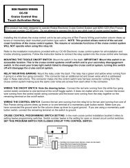
Bag #34. PARK/NEUTRAL RELAY: This system was developed to allow a regular park / neutral<br />
switch to tell the computer when the vehicle is in park, neutral or drive. Since the signals are different, we<br />
have made this small circuit that will plug into a stock GM neutral switch or splice to just about any two<br />
wire neutral switch. The signal input controls the idle air control (IAC), vehicle speed sensor diagnostics<br />
(VSS) and exhaust gas recirculating (EGR).<br />
In order to wire this circuit as easily as possible, follow the<br />
box below that pertains to the way the rest of your vehicle<br />
"is" or "is going to be" wired.<br />
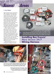
Installation <strong>instructions</strong> using a <strong>Ron</strong> <strong>Francis</strong> wiring kit.<br />
This is a simple, color coded plug-in to GM Neutral Safety Switches. The regular car<br />
wiring that normally runs to the neutral safety now plugs into the P/N relay kit with the with the blue<br />
and purple wires in the black connector. The plug with the blue and black wires is connected to the<br />
original neutral safety switch.<br />
Run the black wire with the ring terminal to a good ground.<br />
The orange wire running from the relay is run to #25 on the Telorvek panel.<br />
Don't forget to install a relay (GM part #14100455).<br />
Installation <strong>instructions</strong> not using a <strong>Ron</strong> <strong>Francis</strong> wiring kit or<br />
installing unit using a neutral safety that the connectors supplied on<br />
the park/neutral relay wires is not correct for your application.<br />
NOTE: Using any other standard neutral switch requires only removing the plug and splicing.<br />
Either color wire can be used on either terminal. The black plug with the light blue and black<br />
wires is connected into your neutral safety switch. If the connector on the wires doesn't fit your<br />
application then remove it and connect the wires to the switch.<br />
The blue wire in the plug must be connected to the 12 volt supply from the ignition<br />
switch. This wire becomes hot (12 Volts) when you turn the key to crank.<br />
<br />
The purple wire is connected to the wire that runs to the starter solenoid.<br />
Run the orange wire to #25 on the Telorvek panel. Don't forget to install a relay<br />
(GM part #14100455).
Page #7<br />
Bag #35. AIR MANAGEMENT SYSTEM: This system is controlled by the ECM. The AIR SELECT<br />
VALVE allows the air pump to pump air through the exhaust system or to the atmosphere. The<br />
CANISTER PURGE solenoid is controlled by the ECM and allows ported manifold vacuum to purge the<br />
vapors from the canister. Canister Purge: Plug in the red connector with the Pink & Dk Green wires<br />
into the canister purge solenoid and run the wires back to the Telorvek panel.<br />
Connect the three Pink wires to the Telorvek panel as follows: (PURGE SOL A->3) to #3 and the (AIR<br />
PORT SOL A->5) wire connect to #5. Connect the Dk Green wire (PURGE SOL B->38) to #38and the<br />
Brown (AIR PORT B->39) to #39<br />
NOTE!<br />
The pink (DIVERT SOL A->5) wire & Black (DIVERT SOL B->40) wires ARE NOT<br />
USED on the 3.1 engine.<br />
Bag #36. POWER STEERING SWITCH: This switch tells the ECM that the vehicle is in a parking<br />
maneuver. The ECM uses this information to compensate for additional engine load by moving the IAC<br />
valve increasing engine RPM. We have supplied the necessary two wires to make this connection<br />
however the connector for the switch is no longer available. To make the connection to the switch reuse<br />
your original connector.<br />
Connect the Lt Blue wire (D13->PW STEER SW) to one of the terminals on the switch (it does not matter<br />
which one) and run the other end to the four gang terminal block mounted next to the Telorvek panel.<br />
Connect it to the LT Blue wire on terminal block printed D13. Connect the black wire (STEER SW-<br />
>GRND) to the other terminal on the switch and run it to a good ground.<br />
VEHICLE SPEED SENSOR (VSS): A VSS signal input is needed on all General Motors TPI engines.<br />
If the ECM does not see that input a CODE 24 WILL SET. The VSS input helps control some of the<br />
EGR and IAC functions. You need to provide this input and prevent this code one of two ways.<br />
Using a 200 or 700 R4 Transmission<br />
The first is most 700 R4 transmissions have the factory pulse generator located in them. This can be<br />
connected into the computer to provide this signal. For the 700 R4 transmission that has a speedometer<br />
cable connector we have developed a pulse generator (part #PG-6A) that installs in line on the cable to<br />
provide the speed signal into the computer. This transmission also requires a torque converter lock-up<br />
signal which is given by the ECM from the input it receives from the pulse generator. The Detail Zone TC-<br />
60 wiring kit includes the wiring for the TCC lock-up and the correct connectors to plug into the factory<br />
pulse generator to make this connection easy.<br />
Other Transmissions<br />
A speed signal into the computer can done simply by purchasing the PG-6A pulse generator. It installs into<br />
the speedometer cable and following the <strong>instructions</strong> will wire into the harness.<br />
If you would like to wire the VSS circuit yourself, terminal #35 is the VSS low (ground side), #36 is the VSS<br />
high (signal) and if you have an electric speedometer terminal #37 is for that connection.<br />
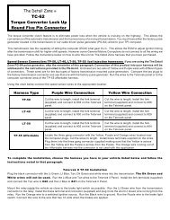
Panel 700R4 Transmission Connections<br />
The Detail Zone offers a wiring kit (TC-60) for the 700R4 transmission which allows the computer<br />
to control torque converter lock-up. If you would like to wire in this circuit yourself, terminal<br />
#41 is the high gear switch and terminal #42 is the torque converter lock-up control.
Page #8<br />
Final Hookups<br />
Connect the large prewired orange wire to the ignition circuit of your ignition switch. This is an ignition<br />
feed that is controlled by the ignition switch. This is not an accessory feed and must remain<br />
hot even when the engine is cranking.<br />
Connect the large prewired red battery feed wire to a battery feed. This is a battery feed that must<br />
remain hot even with the key off. Make sure this is a good connection. If you have a Master<br />
Disconnect switch, install this wire on the battery side of the switch so it will remain hot with the<br />
Disconnect off.<br />
The black ground wire from the TELORVEK II Panel runs direct to the battery. Do not consider<br />
grounding the battery to the frame and then the engine to the frame. Run the battery ground directly to the<br />
engine.<br />
If you turn the key on but do not crank engine, you will hear the fuel pump for about 2 to 4 seconds before<br />
it stops. This will indicate the pump is ready. During normal operating it is best if you do not wait till the<br />
pump stops as this is not an indication that the pressure is up. There is no need to "pump" the throttle on<br />
fuel injection cars.<br />
You have now completed the kit <strong>installation</strong>. You may have noted empty terminals on the Telorvek panel<br />
that do not have any wire connections to them. The Detail Zone runs all computer connections out of the<br />
computer plug(s) even if they are not used in aftermarket applications.<br />
Other Harness Connections<br />
A/C Request: If your vehicle has air conditioning, splice a wire into the wire that runs from the A/C on/off<br />
switch to the A/C thermostat. This wire will become hot when the A/C is turned on. After completing the<br />
splice run the wire to the Telorvek panel and connect it to #7.<br />
A/C Relay Control: Controls the engagement of the A/C compressor clutch. In order to utilize this<br />
circuit you must duplicate the entire A/C system electrical connections from a 90-92 Camaro. Your shop<br />
manual will detail this connection. This wire runs from the computer connector to the four gang terminal<br />
block you mounted earlier, the Dark Green wire marked F1.<br />
Electric Cooling Fan Relay Control: This circuit requires a relay which the computer controls<br />
through terminal #32.<br />
Fan request signal: Pressure signal. In order to utilize this circuit you must duplicate the entire A/C<br />
system electrical connections from a 90-92 Camaro. Your shop manual will detail this connection. This<br />
wire runs from the computer connector to the four gang terminal block you mounted earlier, the Dark Blue<br />
wire marked D12.<br />
POSSIBLE PROBLEMS ARE:<br />
Wrong Prom, ECM or Vacuum leaks. No fuel or Timing incorrectly set, IAC adjustment, Dirty injectors or<br />
fouled plugs if engine runs rich too long. Clogged injectors may need cleaning for proper operation. This<br />
can be accomplished with several methods with commercially available cleaners. Less than 45 PSI fuel<br />
pressure. Less than 194N thermostat.
Page #9<br />
TROUBLE CODES<br />
Listed below are trouble codes the ECM will store in the event of a sensor failure. Inserting the code key<br />
attached to the ALDL connector into terminal A to terminal B (white and black wires) will allow the<br />
computer to "flash" trouble codes in the "CODES" light mounted on the TELORVEK II panel and (or) on<br />
the dash mounted light.<br />
Each code will flash 3 times. Each number is flashed separate. Example: Thirteen is flashed as a single<br />
flash followed by three flashes. This will repeat three times before moving on to any addition codes. Not<br />
all that can go wrong on an EFI computer controlled system will set a service code. If no codes are<br />
present and there is a runabilty problem it may be necessary to connect a scan tool to the system or have<br />
it serviced at a qualified repair facility. The fuel pump can be tested by temporarily connecting a 12 volt<br />
source to the 'G' terminal of the ALDL.<br />
12 Distributor not<br />
turning<br />
13 Oxygen Sensor<br />
14 High temp<br />
15 Very low temp<br />
21 TPS high voltage<br />
22 TPS low voltage<br />
23 MAT low temp<br />
24 Speed Sensor<br />
25 MAT high temp<br />
32 EGR<br />
33 MAP<br />
34 MAP<br />
35 IAC<br />
41 Replace Prom<br />
42 Dist Circuit<br />
43 Excessive Knock<br />
44 Oxygen Lean<br />
45 Oxygen Rich<br />
46 VATS<br />
51 Replace Prom<br />
52 Replace prom<br />
53 Vehicle over<br />
voltage<br />
54 Fuel pump low<br />
voltage<br />
61 Degraded O2<br />
Sensor<br />
RESETTING IAC VALVE PINTLE POSITION: If the IAC was completely out of the manifold for any<br />
reason like polishing, replacement or whatever, resetting will be necessary. Carefully follow the following<br />
<strong>instructions</strong>.<br />
(1) Slightly depress accelerator pedal.<br />
(2) Start and run the engine for five<br />
seconds.<br />
(3) Shut engine off for ten seconds.<br />
(4) Start the engine and check for proper<br />
idle.<br />
TIMING ADJUSTMENT: you must disconnect the special timing plug in the tan wire at the distributor<br />
first. Pull this apart for timing purposes and then reconnect to run. This may cause code 42 to be stored in<br />
the ECM memory. This must be cleared after setting timing or distributor will not<br />
advance properly. This is best done with a scanner but disconnecting the battery for<br />
30 seconds will accomplish the same task. After disconnecting the battery to clear codes etc,<br />
the engine will run poorly at least until it is in closed loop and approximately another 10-15 minutes. If<br />
there are any defective sensors or other parts, this will take much longer.<br />
Computer controlled timing cannot be tricked by setting it higher without causing problems in other<br />
settings. The computer will readjust to a stock setting. set the timing at recommended point only. After<br />
setting timing, turn off engine and reconnect the special timing disconnect plug. This is important that you<br />
use this procedure as too high a timing will case some headaches you don't need.
Page #10<br />
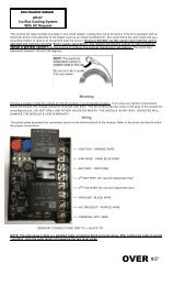
Telorvek Panel Fuse Designation and Size Layout<br />
Fuse Designation & Size<br />
The harness has a total of eight fuses. Shown below is a diagram of what each fuse protects.<br />
Top, Front View Of Fuse Blocks<br />
Fuse Row #1 Fuse Row #2<br />
Fuse<br />
Designation<br />
Fuse Size<br />
Block #1<br />
Fuse<br />
Designation<br />
Fuse Size<br />
Block #2<br />
(BATTERY FEED)<br />
Oil SW, ECM<br />
(BATTERY FEED)<br />
Fuel Pump Relay<br />
(IGNITION FEED)<br />
Canister Purge Solenoid<br />
(IGNITION FEED)<br />
Ignition Coil, ECM<br />
15 AMP (IGNITION FEED)<br />
Air Port<br />
Solenoid<br />
10 AMP (IGNITION FEED)<br />
Left Injectors<br />
10 AMP (IGNITION FEED)<br />
Right Injectors<br />
20 AMP (IGNITION FEED)<br />
EGR Solenoid, S.E.S LT.<br />
10 AMP<br />
5 AMP<br />
5 AMP<br />
10 AMP<br />
Telorvek II Options<br />
CF-69<br />
Map Sensor, Oil Switch, Fuel Pump & Park Neutral<br />
Relay<br />
PG-6A Speed Generator (Pulse Generator)<br />
CF-29 Radiator Cooling Fan & AC Request<br />
OS-30 Oxygen Sensor Adapter (Weld In)<br />
TC-70 Torque Convertor Lock-Up (Stand Alone)<br />
TC-60 Torque Converter Lock-up Computer Controlled<br />
(Square Four Pin Connector) Pulse Generator Required<br />
GM 3.1 Prom part numbers<br />
90-92 16171406 Auto Trans, Federal Emissions<br />
90-92 16171410 Auto Trans, Calif. Emissions<br />
90-92 16176864 Manual Trans, Calif. & Federal Emissions<br />
TC-62 Torque Convertor Lock-Up Computer Controlled<br />
(Round Five Pin Connector) Pulse Generator Required<br />
EC-51<br />
Engine Control Module (ECM) With Approved Core<br />
Return<br />
General Motors Part Numbers<br />
Oil Switch (Two Wire Unit) 25036553<br />
M.A.P. Sensor 16137039<br />
Fuel Pump & Park Neutral Relays 14100455<br />
Computer (ECM) 1227730 or 16196344 or 16198262<br />
Note: If you are in need of the clips with studs and nuts to used properly bolt down the computer,<br />
The clips are available from a GM dealer in packs of 10 under part number 12337892 and the nuts<br />
are available individually under part number 11502702.<br />
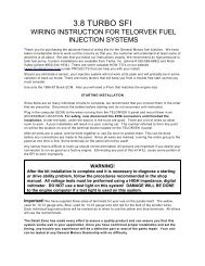
General Motors EFI Connections
Page #11<br />
1) Throttle Position Sensor<br />
2) EGR Solenoid<br />
3) External Coil Distributor<br />
Connector<br />
4) Internal Coil Distributor<br />
Connector<br />
5) Air By-Pass Solenoid<br />
6) ALDL Connector<br />
7) Oxygen Sensor<br />
8) Injectors<br />
9) Knock Sensor<br />
10) Manifold Air Pressure Sensor<br />
11) Idle Air Control<br />
12) Air Divert Solenoid<br />
13) Coolant Temperature Sensor<br />
14) Canister Purge Solenoid
Page #12<br />
Copyright Infringement<br />
The Detail Zone<br />
has taken the<br />
extra effort to<br />
produce a quality, easy to understand <strong>instructions</strong>. We will<br />
aggressively prosecute any other harness supplier who attempts<br />
to copy this material!!