PDF Version - Edwardbosworth.com
PDF Version - Edwardbosworth.com
PDF Version - Edwardbosworth.com

You also want an ePaper? Increase the reach of your titles
YUMPU automatically turns print PDFs into web optimized ePapers that Google loves.
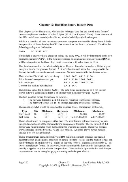
Chapter 12: Handling Binary Integer Data<br />
This chapter covers binary data, which refers to integer data that are stored in the form of<br />
two’s–<strong>com</strong>plement numbers of either 2 bytes (16 bits) or 4 bytes (32 bits). Later versions of<br />
the IBM mainframe, certainly the zSeries, also include 8 byte (64 bit) integers.<br />
While it is true that all data in a stored–program <strong>com</strong>puter are stored in binary form, it is the<br />
interpretation of those data by the CPU that determines the format to be used. Consider the<br />
following ambiguous declaration.<br />
DATA DC X‘81 6C’<br />
If this field is processed as a character string, say usingMVC, it will be interpreted as the two<br />
printable characters “a%”. If the field is processed as a packed decimal, say usingZAP, it<br />
will be interpreted as the three–digit positive number with value equal to +816.<br />
This field contains four hexadecimal digits, or 16–bits. It can be viewed as a 16–bit signed<br />
integer in two’s–<strong>com</strong>plement format. A bit of reflection will show that, interpreted in this<br />
format, the field represents a negative number. We now convert it to the decimal value.<br />
The value itself isX‘81 6C’ or binary 1000 0001 0110 1100.<br />
Take the one’s <strong>com</strong>plement to get 0111 1110 1001 0011.<br />
Add one to get 0111 1110 1001 0100.<br />
Convert this back to hexadecimal X‘7E 94’.<br />
The decimal value for the last is 32,404. The data field, interpreted as an 8–bit integer<br />
stored in two’s–<strong>com</strong>plement form is an integer with the negative value –32,404.<br />
The two standard binary formats are as follows.<br />
F The fullword format is a 32–bit integer, requiring four bytes of storage.<br />
H The halfword format is a 16–bit integer, requiring two bytes of storage.<br />
The ranges are what would be expected for standard two’s–<strong>com</strong>plement arithmetic.<br />
Type Bits Minimum Maximum Minimum Maximum<br />
Half–word 16 –(2 15 ) (2 15 ) – 1 –32,768 32,767<br />
Full–word 32 –(2 31 ) (2 31 ) – 1 –2,147,483,648 2,147,483,647<br />
Those of us trained on <strong>com</strong>puters other than IBM mainframes will unconsciously equate<br />
integer data with one of the standard two’s–<strong>com</strong>plement formats. The 16–bit and 32–bit<br />
forms were rather popular when the System/360 was first designed. These two formats<br />
were continued into the System/370 and later models. As noted above, newer models<br />
include a 64–bit integer format.<br />
Those programmers trained primarily on IBM mainframes might consider the packed<br />
decimal format as an equally good way to handle integers. Recall that the packed format can<br />
handle integers of lengths up to 31 digits, as opposed to the 11 digit maximum on the 32–bit<br />
two’s–<strong>com</strong>plement format. In this view, binary arithmetic is done only in the registers and<br />
usually is applied only for address <strong>com</strong>putations. Your author’s opinion is that each integer<br />
representation has its strengths; pay your money and take your choice.<br />
Page 220 Chapter 12 Last Revised July 6, 2009<br />
Copyright © 2009 by Edward L. Bosworth, Ph.D.
S/370 Assembler Language Binary Integer Data<br />
Declaring Binary Storage<br />
There are many ways to declare binary storage. The four most useful are<br />
1. B Ordinary binary,<br />
2. F Full–word (32–bit binary two’s–<strong>com</strong>plement integer),<br />
3. H Half–word (16–bit) binary two’s–<strong>com</strong>plement integer), and<br />
4. X Hexadecimal.<br />
Each of the B and X declarations may declare a storage area with length from 1 through 256<br />
bytes. The lengths of the F and H declarations are fixed at 4 and 2 bytes respectively.<br />
Apparently, it is possible to assign a length in bytes to either type, but this is strange.<br />
Note that the two declarations below have an identical effect. Each defines a 32–bit binary<br />
integer with value equal to 14,336 in decimal.<br />
F1 DC F‘14336’ DEFAULT SIZE IS FOUR BYTES.<br />
X1<br />
DC XL4‘00003800’ SIZE SPECIFIED AS FOUR BYTES.<br />
While the second declaration is unusual for a full–word, it makes some examples easier.<br />
More On DC (Define Constant)<br />
The general format of the DC statement is as follows.<br />
Name DC dTLn ‘constant’<br />
The name is an optional entry, but required if the program is to refer to the field by name.<br />
The standard column positions apply here.<br />
The declarative, DC, <strong>com</strong>es next in its standard position.<br />
The entry “dTLn” is read as follows.<br />
d is the optional duplication factor. If not specified, it defaults to 1.<br />
T is the required type specification. The types for binary are B, F, H, and X.<br />
Note that the data actually stored at the location does not need to be<br />
of this type, but it is a good idea to restrict it to that type.<br />
L<br />
is an optional length of the data field in bytes.<br />
The ‘constant’ entry is required and is used to specify a value. If the length attribute is<br />
omitted, the length is specified implicitly by this entry. Again, it is rarely desirable<br />
to specify a length for the F and H data types.<br />
Alignment and Value Ranges<br />
Remember that the System/360 is a byte–addressable machine. The type F declares a full–<br />
word, which is a four–byte field aligned on a full–word boundary; i.e., its address is a<br />
multiple of four. The type H declares a half–word, which is a two–byte field aligned on a<br />
half–word boundary; i.e., its address is a multiple of two.<br />
If the value declared in either a type F or type H constant is greater than that<br />
allowed by the data type, the assembler merely truncates the leftmost digits.<br />
Page 221 Chapter 12 Last Revised July 6, 2009<br />
Copyright © 2009 by Edward L. Bosworth, Ph.D.
S/370 Assembler Language Binary Integer Data<br />
Consider the following example<br />
BAD<br />
DC H‘73728’ IN HEXADECIMAL, X‘12000’<br />
This is truncated to a value of 8,192, which is X‘2000’. The leading 1 is dropped<br />
from the hexadecimal representation, because only the last four digits fit into the<br />
half–word storage allocation; 4 hexadecimal digits = 2 bytes = 1 half–word.<br />
Sequential Memory<br />
Consider the following two declarations which are sequential. Each is a half–word,<br />
which is declared using the hexadecimal construct to make the example clear.<br />
H1 DC XL2‘0102’ DECIMAL 258<br />
H2 DC XL2‘0304’ DECIMAL 772 At address H1+2<br />
The half–word value stored at address H1 is hexadecimal0102 or decimal258.<br />
The full–word value stored at address H1 is hexadecimal01020304, or<br />
16, 909, 060 in decimal. This fact can present problems for the incautious coder.<br />
To load the value of the half–word at address H1 into a register, one uses the Load<br />
Half–word instruction; e.g.,LH R4,H1. Register R4 gets 258. But if I accidentally write a<br />
full–word load instruction, as inL R4,H1, then register R4 will get the decimal value<br />
16, 909, 060. This is due to the fact that the four bytes beginning at address H1 have the<br />
valueX‘0102 0304’. The fact that H1 and H2 are defined separately matters not at all.<br />
Similarly, suppose I declare a full–word as follows.<br />
F1 DC XL4 ‘11121314’ DECIMAL 17,899,828<br />
If the code saysLH R4,F1, then F1 gets hexadecimal X‘1112’ or decimal 4370.<br />
Binary Constants and Hexadecimal Constants<br />
The type B declaration uses binary numbers (0 or 1) to define a string of bits. The type X<br />
declaration uses hexadecimal digits to define what is also just a string of bits.<br />
Consider the following pairs of declarations.<br />
B1 DC B‘10101110’<br />
X1 DC XL1‘AE’ READ AS 1010 1110<br />
B2 DC B‘0001001000010011’<br />
X2 DC XL2‘1213’ READ AS 0001 0010 0001 0011<br />
B1 and X1 each declare the same bit pattern.<br />
B2 and X2 each declare the same bit pattern.<br />
Personally, I find the hexadecimal constants much easier to read, and would suggest not<br />
using the B declaration. The most <strong>com</strong>mon use for the binary declaration would be to set bit<br />
patterns to be sent to registers that control Input/Output devices. In standard programming,<br />
we do not have access to those registers on a System/360 or later mainframe..<br />
Page 222 Chapter 12 Last Revised July 6, 2009<br />
Copyright © 2009 by Edward L. Bosworth, Ph.D.
S/370 Assembler Language Binary Integer Data<br />
Input and Output of Binary Data<br />
All data are input originally as EBCDIC characters.<br />
All data printed must be output as EBCDIC characters.<br />
The standard input process for binary data is a two–step one, in which the character<br />
data are first packed to form decimal data and then converted to binary.<br />
The standard process to output binary data from a register is also a two–step one.<br />
First convert the binary to decimal data and then use unpack or the edit instruction<br />
to produce the printable EBCDIC characters.<br />
Conversion between Packed Decimal and Binary<br />
These two conversion instructions are each a type RX instruction.<br />
CVB (Convert to Binary) converts packed decimal data from storage into binary form in a<br />
general–purpose register. This is a type RX instruction with opcodeX‘4F’.<br />
CVD (Convert to Decimal) converts binary data in a general–purpose register into packed<br />
decimal form in storage. This is a type RX instruction with opcodeX‘4E’.<br />
The format of each isOP R1,D2(X2,B2).<br />
Template for the instructions:<br />
CVB Register,Storage_Location<br />
CVD Register,Storage_Location<br />
For the CVB instruction, the Storage Location contains the packed decimal value that<br />
is to be converted to binary and placed in the register.<br />
For the CVD instruction, the Storage Location is the field that will receive the packed<br />
decimal value resulting from the conversion of the value in the register.<br />
It is standard practice to use the floating point data type D (double word) to<br />
declare the storage location.<br />
Page 223 Chapter 12 Last Revised July 6, 2009<br />
Copyright © 2009 by Edward L. Bosworth, Ph.D.
S/370 Assembler Language Binary Integer Data<br />
Why A Floating Point Type Here?<br />
The D data type declares a double precision floating point value, which occupies eight bytes<br />
(64 bits) and is automatically aligned on a double–word boundary. In other words, its<br />
address is a multiple of 8. The true requirement for the operand is that it be exactly eight<br />
bytes long and begin on a double–word boundary. The D declaration fills the bill.<br />
Consider the following code, which is rather standard.<br />
CVB R6,D1<br />
D1 DS D DOUBLE WORD OR 8 BYTES<br />
One might also write the following, if one is careful.<br />
CVB R6,D2<br />
D2 DS PL8 EIGHT BYTES FOR UP TO 15 DIGITS<br />
The difficulty here is insuring that D2 is properly aligned on a double–word boundary.<br />
While this can be done, it is less error–prone to use the D type and have the assembler<br />
automatically do the alignment for you.<br />
Example and Comments<br />
How many digits do I really need? The biggest value storable as a 32–bit binary number is<br />
2,147,483,647. This number has 10 digits, which will be converted to 11 digits for storage in<br />
Packed Decimal format. A 4–byte full–word will store only seven digits. It takes a six–byte<br />
packed decimal field to store 11 digits. There is no data size that automatically takes 6 bytes<br />
and no provision for aligning an address on a multiple of six. The obvious choice for the<br />
packed decimal intermediary form is storage as a double–word.<br />
Input example<br />
ZAP D1,AMTPACK TRANSFER TO THE DOUBLE WORD<br />
CVB R5,D1 CONVERT TO BINARY<br />
D1 DS D THIS RESERVES EIGHT BYTES<br />
Output example<br />
CVD R5,D2 PLACE INTO A DOUBLE WORD<br />
ZAP AMTPACK,D2 TRANSFER TO THE PACKED WORD<br />
D2 DS D THIS ALSO RESERVES EIGHT BYTES<br />
Each of these examples assumes that a field,AMTPACK in each, has been properly declared<br />
with the proper length. Recall that each example is a part of a larger process.<br />
The input process has several steps:<br />
1. Read in the sequence of digits as EBCDIC characters.<br />
2. Use the PACK <strong>com</strong>mand to place the result in the fieldAMTPACK.<br />
3. Use the above sequence to convert the number to binary form in the register.<br />
The output process has several steps:<br />
1. Use the above sequence to convert the binary number in the register to<br />
a packed form in the fieldAMTPACK.<br />
2. Use UNPK or ED, preferably the latter, to generate the EBCDIC characters<br />
that form the printable output.<br />
Page 224 Chapter 12 Last Revised July 6, 2009<br />
Copyright © 2009 by Edward L. Bosworth, Ph.D.
S/370 Assembler Language Binary Integer Data<br />
RX (Register–Indexed Storage): Explicit Base Register Usage<br />
This is a four–byte instruction of the form OP R1,D2(X2,B2).<br />
Type Bytes Operands 1 2 3 4<br />
RX 4 R1,D2(X2,B2) OP R 1 X 2 B 2 D 2 D 2 D 2<br />
The first byte contains the 8–bit instruction code.<br />
The second byte contains two 4–bit fields, each of which encodes a register number. The<br />
first hexadecimal digit, denoted R 1 , identifies the register to be used as either the source or<br />
destination for the data. The second hexadecimal digit, denoted X 2 , identifies the register to<br />
be used as the index. If the value is 0, indexed addressing is not used.<br />
The third and fourth bytes contain a standard address in base/displacement format.<br />
As an examples of this type, we consider the two following instructions:<br />
L Load Fullword Opcode isX‘58’<br />
A Add Fullword Opcode isX‘5A’<br />
We consider a number of examples based on the following data declarations. Note that the<br />
data are defined in consecutive fullwords in memory, so that fixed offset addressing can be<br />
employed. Each fullword has a length of four bytes.<br />
DAT1 DC F‘1111’<br />
DAT2 DC F‘2222’ AT ADDRESS (DAT1 + 4)<br />
DAT3 DC F‘3333’ AT ADDRESS (DAT2 + 4) OR (DAT1 + 8)<br />
A standard code block might appear as follows.<br />
L R5,DAT1<br />
A R5,DAT2<br />
A R5,DAT3 NOW HAVE THE SUM.<br />
One variant of this code might be the following. See page 92 of R_17.<br />
LA R3,DAT1 GET ADDRESS INTO R3<br />
L R5,0(,3) LOAD DAT1 INTO R5<br />
A R5,4(,3) ADD DAT2, AT ADDRESS DAT1+4.<br />
A R5,8(,3) ADD DAT3, AT ADDRESS DAT1+8.<br />
Note the leading <strong>com</strong>ma in the construct(,3), which is of the form (Index, Base). This<br />
indicates that no index register is being used, but that R3 is being used as a base register. It is<br />
equivalent to the construct(0,3), which might be preferred.<br />
Here is another variant of the above code.<br />
LA R3,DAT1 GET ADDRESS INTO R3<br />
LA R8,4 VALUE 4 INTO REGISTER 8<br />
LA R9,8 VALUE 8 INTO REGISTER 9<br />
L R5,0(0,3) LOAD DAT1 INTO R5<br />
A R5,0(8,3) ADD DAT2, AT ADDRESS DAT1+4.<br />
A R5,0(9,3) ADD DAT3, AT ADDRESS DAT1+8.<br />
Page 225 Chapter 12 Last Revised July 6, 2009<br />
Copyright © 2009 by Edward L. Bosworth, Ph.D.
S/370 Assembler Language Binary Integer Data<br />
Loading Values: L, LH, LR, and LCR<br />
The general–purpose registers are designed to store and manipulate binary data that are<br />
stored in the form of 32–bit two’s–<strong>com</strong>plement integers. As an aside, remember two facts<br />
about such numbers.<br />
1. The IBM standard is to number the bits from left to right as 0 through 31.<br />
The sign bit is called “Bit 0” and the units bit on the right “Bit 31”.<br />
2. IBM will often call this “31 bit data”, as the value has a 31–bit magnitude<br />
(stored in bits 1 – 31) and a sign bit.<br />
We first discuss three of the standard instructions used to load values into a register.<br />
L<br />
LH<br />
LR<br />
Note:<br />
LCR<br />
Load a full–word value into the register.<br />
Load a half–word value into the register.<br />
The 16–bit value is sign extended into 32–bits for the register.<br />
Copy a value from one register to another register.<br />
Load the first register with the two’s–<strong>com</strong>plement of the value in the second.<br />
None of these instructions will set a condition code.<br />
Do not load a register and expect a condition code to reflect the value loaded.<br />
L (Load 32–bit Full–word)<br />
The instruction is a type RX, with formatL R1,D2(X2,B2). The opcode isX‘58’. The<br />
object code format is as follows.<br />
Type Bytes Operands 1 2 3 4<br />
RX 4 R1,D2(X2,B2) X‘58’ R 1 X 2 B 2 D 2 D 2 D 2<br />
The first operand specifies any general–purpose register. This is indicated by the first<br />
hexadecimal digit in the second byte of the object code.<br />
The second operand references a full–word in storage, usually aligned on a full–word<br />
boundary. If the second operand is a literal, the assembler will align it properly. The address<br />
of this second word is <strong>com</strong>puted from the standard base/displacement form (B 2 D 2 D 2 D 2 in<br />
bytes 3 and 4) with an index register (the second hexadecimal digit in byte 2).<br />
Here is a template for the instruction:<br />
L Reg,Full_Word<br />
Here are some examples of <strong>com</strong>mon usage. Other examples will be discussed later.<br />
L1 L R2,=F‘4000’ R2 GETS DECIMAL 4000<br />
L2 L R3,F1 R3 ALSO GETS DECIMAL 4000<br />
L3 L R4,H1 THIS IS PROBABLY A MISTAKE.<br />
L4 L R5,=A(H1) LOAD THE ADDRESS INTO R5.<br />
F1 DC F‘4000’<br />
H1 DC H‘2000’ Stored as X‘07 D0’<br />
H2 DC H‘3000’ Stored as X‘0B B8’<br />
Note again, it is usually a mistake to attempt to use a full–word load to place a half–word<br />
value into a register. What will happen when the instruction at addressL3 is executed is that<br />
register R4 will be loaded with the valueX‘07 D0 0B B8’, or decimal 131, 075, 000.<br />
Page 226 Chapter 12 Last Revised July 6, 2009<br />
Copyright © 2009 by Edward L. Bosworth, Ph.D.
S/370 Assembler Language Binary Integer Data<br />
The execution of the instruction at addressL4 causes the address of the halfwordH1, not its<br />
value, to be loaded into registerR5. For the System/370, the address is a 24–bit unsigned<br />
integer that is extended to a 32–bit value for storage in the register.<br />
LH (Load 16–bit Half–word)<br />
The instruction is a type RX, with formatLH R1,D2(X2,B2). The opcode isX‘48’.<br />
The object code format is as follows.<br />
Type Bytes Operands 1 2 3 4<br />
RX 4 R1,D2(X2,B2) X‘48’ R 1 X 2 B 2 D 2 D 2 D 2<br />
The first operand specifies any general–purpose register. This is indicated by the first<br />
hexadecimal digit in the second byte of the object code.<br />
The second operand references a full–word in storage, usually aligned on a half–word<br />
boundary. If the second operand is a literal, the assembler will align it properly. The address<br />
of this second word is <strong>com</strong>puted from the standard base/displacement form (B 2 D 2 D 2 D 2 in<br />
bytes 3 and 4) with an index register (the second hexadecimal digit in byte 2).<br />
The assembler loads the half–word into the rightmost 16 bits of the register (16 – 31)<br />
and then propagates the half–word’s sign bit through the left 16 bits of the register.<br />
Here is a template for the instruction: LH Reg,Half_Word<br />
Here are some examples of <strong>com</strong>mon usage. Other examples will be discussed later.<br />
L1 LH R2,=H‘4000’ R2 GETS DECIMAL 4000<br />
L2 LH R3,H1 R3 GETS DECIMAL 2000<br />
L3 LH R4,F1 THIS IS PROBABLY A MISTAKE.<br />
F1 DC F‘4000’ Stored as X‘00 00 0F A0’<br />
H1<br />
DC H‘2000’<br />
The difficulty with the instruction at addressL3 is that it will access the two bytes at the<br />
addressesF1 andF1+1. The halfword stored there has valueX‘00 00’, or just 0.<br />
Sign Extension for LH<br />
Consider two 16–bit integers that are stored as half–words in two’s–<strong>com</strong>plement form.<br />
The positive number + 100 is stored as 0000 0000 0110 0100, orX‘0064’.<br />
The negative number –100 is stored as 1111 1111 1001 1100 orX‘FF9C’<br />
The LH sign extends the halfword data into fullword data with the proper sign. This it does<br />
by copying bits 0 through 15 of the halfword into bits 16 through 31 of the register and then<br />
copying the sign bit (now in register bit 16) into bits 0 through 15 of the register.<br />
Page 227 Chapter 12 Last Revised July 6, 2009<br />
Copyright © 2009 by Edward L. Bosworth, Ph.D.
S/370 Assembler Language Binary Integer Data<br />
Consider the code fragment below.<br />
LH R7,=H‘100’<br />
After this, register R7 contains the full–word value +100, as shown below.<br />
Left half–word<br />
Right half–word<br />
0 – 3 4 – 7 8 – 11 12 – 15 16 – 19 20 – 23 24 – 27 28 – 31<br />
0000 0000 0000 0000 0000 0000 0110 0100<br />
Now consider the code fragment.<br />
LH R8,=H‘-100’<br />
After this, register R8 contains the full–word value –100, as shown below.<br />
Left half–word<br />
Right half–word<br />
0 – 3 4 – 7 8 – 11 12 – 15 16 – 19 20 – 23 24 – 27 28 – 31<br />
1111 1111 1111 1111 1111 1111 1001 1100<br />
LR (Load Register) and LCR (Load Complement Register)<br />
Each instruction is a type RR, with formatLR R1,R2. The opcode forLR isX‘18’.<br />
The opcode forLCR isX‘13’. The object code format for each is as follows.<br />
Type Bytes Operands<br />
RR 2 R1,R2 OP R 1 R 2<br />
Each operand specifies any general–purpose register. The contents of the register specified<br />
as the second operand are copied into the register specified as the first operand.<br />
Consider the code fragment below.<br />
L R9,=H‘200’ REGISTER 9 GETS DECIMAL 200<br />
LR R7,R9 REGISTER 7 ALSO GETS 200<br />
THIS TIME IT IS COPIED FROM R9<br />
LCR R8,R9<br />
REGISTER 8 GETS DECIMAL -200, STORED<br />
IN PROPER 2’S-COMPLEMENT FORMAT.<br />
LM (Load Multiple Registers)<br />
The LM instruction loads data from main storage into more than one register.<br />
The instruction is a type RS with formatLM R1,R3,D2(B2). The opcode isX‘98’.<br />
This is a four–byte instruction with object code format as follows:<br />
Type Bytes Operands 1 2 3 4<br />
RS 4 R1,R3,D2(B2) X‘98’ R 1 R 3 B 2 D 2 D 2 D 2<br />
The first byte contains the 8–bit instruction code.<br />
The second byte contains two 4–bit fields, each of which encodes a register number. These<br />
two bytes specify the range of registers to be loaded.<br />
The third and fourth bytes together contain a 4–bit register number and 12–bit displacement<br />
used to specify the memory address of the operand in storage. This operand is considered as<br />
the first fullword a block of fullwords; the size of the block is determined by the number of<br />
registers specified in byte 2. This is a type RS instruction; indexed addressing is not used.<br />
Page 228 Chapter 12 Last Revised July 6, 2009<br />
Copyright © 2009 by Edward L. Bosworth, Ph.D.
S/370 Assembler Language Binary Integer Data<br />
Recall that each label in the assembly language program references an address,<br />
which must be expressed in the form of a base register with displacement.<br />
Any address in the format of base register and displacement will appear in the form.<br />
B D 1 D 2 D 3<br />
B is the hexadecimal digit representing the base register.<br />
The register numbers “wrap around”, so that15,1 specifies the three registers 15, 0, 1.<br />
Example code:<br />
F1<br />
F2<br />
F3<br />
F4<br />
LM R6,R8,F1<br />
LM R15,R2,F1<br />
DC F‘1111’<br />
DC F‘2222’<br />
DC F‘3333’<br />
DC F‘4444’<br />
LOAD R6, R7, R8 FROM F1, F2, F3<br />
LOAD R15, R0, R1, R2 FROM F1 TO F4<br />
LM and the Standard Closing Code<br />
Look again at part of the standard closing code for our programs.<br />
******************* END LOGIC **************************<br />
L R13,SAVEAREA+4 POINT AT OLD SAVE AREA<br />
LM R14,R12,12(R13) RESTORE THE REGISTERS<br />
LA R15,0 RETURN CODE = 0<br />
BR R14 RETURN TO OPERATING SYSTEM<br />
The labelSAVEAREA references a sequence of full words used to save information<br />
used when returning to the operating system.<br />
The second full–word in this area, at addressSAVEAREA+4, holds the address of<br />
the block of memory used to save the register information.<br />
The instructionLM R14,R12,12(R13) loads the 15 registers R14 through R12, omitting<br />
only R13, with the 15 full–word values beginning at the specified address. More<br />
specifically, the old register values are saved in a block beginning with the fourth full–word<br />
(at offset 12) in the block with address now in R13. The address12(R13) is specified in<br />
base/displacement format and references the start address of the 60–byte part of the save area<br />
that is used to store the values of the registers.<br />
The instructionLA R15,0 is a use of a Load Address instruction that we shall discuss<br />
very shortly. I would prefer something likeLH R15,=H‘0’, which appears to be<br />
equivalent, but can lead to addressability issues. TheLA format is safer.<br />
Page 229 Chapter 12 Last Revised July 6, 2009<br />
Copyright © 2009 by Edward L. Bosworth, Ph.D.
S/370 Assembler Language Binary Integer Data<br />
Loading Addresses<br />
Up to now, we have discussed “value loaders”, such as the following example.<br />
L R3,FW1<br />
This finds the full–word at address FW1 and loads its value into register R3.<br />
At times, we shall need not the value stored at an address but the address itself.<br />
One possibility would be to store a return address to be used by a subroutine.<br />
There are two <strong>com</strong>mon ways to access the address and store it into a register.<br />
1. Use the L (Load full–word) instruction and use an address literal<br />
2. Use the LA (Load Address) instruction and use the label.<br />
The following two statements are equivalent. Each loadsR1 with the addressFW1.<br />
L R1,=A(FW1)<br />
LA R1,FW1<br />
In the System/360 and System/370 the address is treated as a 24–bit unsigned integer,<br />
which can be represented by six hexadecimal digits.<br />
If the address of FW1 isX‘112233’, register R1 getsX‘00112233’.<br />
LA (Load Address)<br />
The instruction is a type RX, with formatLA R1,D2(X2,B2). The opcode isX‘41’.<br />
The object code format is as follows.<br />
Type Bytes Operands 1 2 3 4<br />
RX 4 R1,D2(X2,B2) X‘41’ R 1 X 2 B 2 D 2 D 2 D 2<br />
Here is a template for the instruction: LA Reg,Address<br />
The first operand specifies any general–purpose register. This is indicated in the<br />
object code by the first hexadecimal digit in the second byte.<br />
The second operand references a storage address in the formD2(X2,B2). The index<br />
register is specified by the second hexadecimal digit in the second byte. Bytes 3 and 4<br />
together contain an address in base/displacement form, to which the index value is added.<br />
Consider the following fragment of code, which indicates one use of the instruction.<br />
A10<br />
LA R9,A10<br />
DC F‘100’<br />
Suppose that label A10 is subject to base register 3 containing valueX‘9800’<br />
with a displacement ofX‘260’. The object code for the LA instruction is as follows.<br />
41 90 32 60<br />
The code for theLA instruction isX‘41’. The second byte“90” is of the form R1X2,<br />
where R1 is the target register and X2 is the index register. As is standard, a value of 0<br />
indicates that indexing is not used in this address; it is pure base/displacement form.<br />
The LA instruction causes register R9 to be get valueX‘9800’ + X‘260’ = X‘9A60’.<br />
Page 230 Chapter 12 Last Revised July 6, 2009<br />
Copyright © 2009 by Edward L. Bosworth, Ph.D.
S/370 Assembler Language Binary Integer Data<br />
LA: A Second Look<br />
The instruction is a type RX, with formatLA R1,D2(X2,B2).<br />
Consider the example above, coded asLA R9,X‘260’(0,3).<br />
Again, the object code for this is41 90 32 60.<br />
Let’s analyze this object code. What it says is the following:<br />
1) Take the contents of register 3 X‘9800’<br />
2) Add the value of the offset X‘260’<br />
3) Add the contents of the index X‘000’<br />
(here no index register is used)<br />
4) Get the value X‘9A60’<br />
5) Place that value into register R9, which now contains X‘0000 9A60’.<br />
But note:<br />
While we call this an address, it is really just an unsigned binary number.<br />
This gives rise to a <strong>com</strong>mon use of the LA instruction to load a constant<br />
value into a general–purpose register.<br />
LA: Load Register with Explicit Value<br />
Consider the instructionLA R8,4(0,0).<br />
The object code for this is41 80 00 04.<br />
The code is executed assuming no base register and no index register.<br />
The number 4 is <strong>com</strong>puted and loaded into register 8.<br />
The following instruction is considered identical:LA R8,4.<br />
Note that the second operand in this form of the instruction is a non–negative<br />
integer that is treated by the assembler as a displacement.<br />
This implies that the value must be in a form that can be represented as a 12–bit unsigned<br />
integer, specifically that it must be a non–negative integer not larger than 4,095 (decimal).<br />
Consider now the line from the standard ending code of our programs.<br />
LA R15,0 RETURN CODE = 0<br />
This places the value 0 into the destination register.<br />
Instructions: Surface Meaning and Uses<br />
In the previous example, we see a trick that is <strong>com</strong>monly used by assembly language<br />
programmers: find what the instruction really does and exploit it. The surface meaning of the<br />
LA instruction is simple: load the address of a label or symbolic address into a given register.<br />
The usage to load a register with a small non–negative constant value is an immediate and<br />
logical result of the way the object code is executed. The goals of such tricks seem to be:<br />
1) To gain coding efficiency, and<br />
2) To avoid addressing problems that sometimes arise in the use of literals.<br />
Page 231 Chapter 12 Last Revised July 6, 2009<br />
Copyright © 2009 by Edward L. Bosworth, Ph.D.
S/370 Assembler Language Binary Integer Data<br />
Storing Register Values: ST, STH, and STM<br />
ST (Store Full Word) is a type RX instruction, with formatST R1,D2(X2,B2).<br />
STH (Store Half Word) is a type RX instruction, with formatSTH R1,D2(X2,B2).<br />
STM (Store Multiple) is a type RS instruction, with formatSTM R1,R3,D2(B2).<br />
The ST instruction stores the full–word contents of the register, specified in the<br />
first operand, into the full word at the address specified by the second operand.<br />
The STH instruction stores the rightmost 16 bits of the register specified by the<br />
first operand into the half word at the address specified by the second operand.<br />
For STM (Store Multiple Registers), the first two operands specify a range of<br />
registers to be stored. Remember that the register numbers “wrap around”<br />
STM R7,R10,X2<br />
STM R10,R7,X4<br />
STORE THE FOUR REGISTERS R7,R8,R9,AND R10<br />
INTO FOUR FULL-WORDS BEGINNING AT X2<br />
STORE THE 14 REGISTERS R10 THROUGH R7<br />
(ALL BUT R8 AND R9) INTO 14 FULL-WORDS<br />
While each of these instructions is quite similar to its load register partner, we shall<br />
spend a bit of time discussing the instructions. After all, this is a textbook.<br />
ST: Store Fullword<br />
The ST (Store Full Word) is a type RX instruction, with formatST R1,D2(X2,B2)<br />
and opcodeX‘50’. The object code format is as follows:<br />
Type Bytes Operands 1 2 3 4<br />
RX 4 R1,D2(X2,B2) X‘50’ R 1 X 2 B 2 D 2 D 2 D 2<br />
The first operand specifies any general–purpose register. This is indicated by the first<br />
hexadecimal digit in the second byte of the object code.<br />
The second operand references a full–word in storage, usually aligned on a full–word<br />
boundary. The address of this second word is <strong>com</strong>puted from the standard base/displacement<br />
form (B 2 D 2 D 2 D 2 in bytes 3 and 4) with an index register (the second hexadecimal digit in<br />
byte 2). Here is a template for the instruction: ST Reg,Full_Word<br />
Here are some examples of <strong>com</strong>mon usage. Other examples will be discussed later.<br />
Suppose that R3 contains the decimal value 163840, which isX‘0002 8000’.<br />
ST1 ST R3,F1<br />
ST2 ST R3,H1 NOTE THE TYPE MISMATCH.<br />
F1 DC X‘0000 0000’<br />
H1 DC X‘0000’<br />
H2 DC X‘0000’<br />
The instruction at addressST1 works as advertised, storing the register value into the<br />
fullword at the given address. The instruction at addressST2 is almost certainly a mistake.<br />
The register value is stored into the four bytes beginning at addressH1. HalfwordH1 is set<br />
to the valueX‘0002’ and halfwordH2 is set to the valueX‘8000’.<br />
Page 232 Chapter 12 Last Revised July 6, 2009<br />
Copyright © 2009 by Edward L. Bosworth, Ph.D.
S/370 Assembler Language Binary Integer Data<br />
STH: Store Halfword<br />
The STH (Store Half Word) is a type RX instruction, with formatST R1,D2(X2,B2)<br />
and opcodeX‘40’. This instruction stores the rightmost 16 bits (bits 16 – 31) of the source<br />
register into the halfword at the given address. The object code format is as follows:<br />
Type Bytes Operands 1 2 3 4<br />
RX 4 R1,D2(X2,B2) X‘40’ R 1 X 2 B 2 D 2 D 2 D 2<br />
The first operand specifies any general–purpose register. This is indicated by the first<br />
hexadecimal digit in the second byte of the object code.<br />
The second operand references a half–word in storage, usually aligned on a half–word<br />
boundary. The address of this second word is <strong>com</strong>puted from the standard base/displacement<br />
form (B 2 D 2 D 2 D 2 in bytes 3 and 4) with an index register (the second hexadecimal digit in<br />
byte 2). Here is a template for the instruction: ST Reg,Half_Word<br />
Here are some examples of <strong>com</strong>mon usage. Other examples will be discussed later.<br />
Suppose that R3 contains the decimal value 163840, which isX‘0002 8000’.<br />
ST1 STH R3,F1 NOTE THE TYPE MISMATCH.<br />
ST2 STH R3,H1<br />
F1 DC X‘0000 0000’<br />
H1 DC X‘0000’<br />
H2 DC X‘0000’<br />
The instruction at addressST2 works as advertised, though perhaps not as intended. The<br />
rightmost 16 bits of registerR3 contain a value represented in hexadecimal asX‘8000’.<br />
This value is copied into the halfword at addressH1, correctly setting its value.<br />
The instruction at addressST1 is almost certainly a mistake. It loads the halfword at address<br />
F1 with the hexadecimal valueX‘8000’. Note that it does not matter that the assembly<br />
listing definesF1 as a fullword. The halfword at addressF1 <strong>com</strong>prises the two bytes, the<br />
first at addressF1 and the second at addressF1+1. After this instruction is executed, F1<br />
contains the valueX‘8000 0000’; the rightmost 16 bits have been copied into the two<br />
leftmost bytes associated with the addressF1.<br />
STM: Store Multiple Registers<br />
The STM instruction stores data from one or more registers into main memory.<br />
The instruction is a type RS with formatSTM R1,R3,D2(B2). The opcode isX‘98’.<br />
This is a four–byte instruction with object code format as follows:<br />
Type Bytes Operands 1 2 3 4<br />
RS 4 R1,R3,D2(B2) X‘98’ R 1 R 3 B 2 D 2 D 2 D 2<br />
The first byte contains the 8–bit instruction code.<br />
The second byte contains two 4–bit fields, each of which encodes a register number. These<br />
two bytes specify the range of registers to be loaded.<br />
Page 233 Chapter 12 Last Revised July 6, 2009<br />
Copyright © 2009 by Edward L. Bosworth, Ph.D.
S/370 Assembler Language Binary Integer Data<br />
The third and fourth bytes together contain a 4–bit register number and 12–bit displacement<br />
used to specify the memory address of the operand in storage. This operand is considered as<br />
the first fullword a block of fullwords; the size of the block is determined by the number of<br />
registers specified in byte 2. This is a type RS instruction; indexed addressing is not used.<br />
Since this is a type RS instruction, indexed addressing is not used.<br />
Recall that each label in the assembly language program references an address,<br />
which must be expressed in the form of a base register with displacement.<br />
Any address in the format of base register and displacement will appear in the form.<br />
B D 1 D 2 D 3<br />
B is the hexadecimal digit representing the base register.<br />
The register numbers “wrap around”, so that15,1 specifies the three registers 15, 0, 1.<br />
Example code:<br />
F1<br />
F2<br />
F3<br />
F4<br />
STM R6,R8,F1<br />
STM R15,R2,F1<br />
DC F‘1111’<br />
DC F‘2222’<br />
DC F‘3333’<br />
DC F‘4444’<br />
STORE R6, R7, R8 INTO F1, F2, F3<br />
STORE R15, R0, R1, R2 INTO<br />
F1, F2, F3, F4<br />
Standard Boilerplate Code<br />
Once again, we examine some of the standard code used in all of our programs.<br />
The standard startup code includes the following fragment.<br />
SAVE (14,12)<br />
This macro generates the following code.<br />
SAVE THE CALLER’S REGISTERS<br />
STM 14,12,12(13) STORE REGISTERS 14 THROUGH 12<br />
(15 IN ALL) INTO THE ADDRESS<br />
12 OFFSET FROM BASE REGISTER 13.<br />
We might have concluded our code with the macro<br />
RETURN (14,12)<br />
This expands into the code we actually use in our programs.<br />
LM 14,12,12(13)<br />
LA R15,0 RETURN CODE = 0<br />
BR R14 RETURN TO OPERATING SYSTEM<br />
Page 234 Chapter 12 Last Revised July 6, 2009<br />
Copyright © 2009 by Edward L. Bosworth, Ph.D.
S/370 Assembler Language Binary Integer Data<br />
Binary Arithmetic: Addition and Subtraction<br />
There are six instructions for addition and subtraction.<br />
Mnemonic Description Type Format<br />
A Add full–word to register RX A R1,D2(X2,B2)<br />
S Subtract full–word from register RX S R1,D2(X2,B2)<br />
AH Add half–word to register RX AH R1,D2(X2,B2)<br />
SH Subtract half–word from register RX SH R1,D2(X2,B2)<br />
AR Add register to register RR AR R1,R2<br />
SR Subtract register from register RR SR R1,R2<br />
In each of these, the first operand is a register. It is this register that has its<br />
value changed by the addition or subtraction.<br />
For the half–word instructions (AH and SH), the second operand references a half–word<br />
storage location. The 16–bit contents of this location are sign extended to a full 32–bit word<br />
before the arithmetic is performed.<br />
Binary Arithmetic: Half–word arithmetic<br />
Examples of the instructions<br />
FW1 DC F‘2’<br />
FW2 DC F‘4’<br />
FW3 DC F‘0’<br />
L R7,FW1 LOAD REGISTER FROM FW1<br />
A R7,FW2 ADD FW2 TO REGISTER 7<br />
S R7,=F‘2’ SUBTRACT 2 FROM R7<br />
ST R7,FW3 STORE VALUE IN R7 INTO FW3<br />
AR R7,R8 ADD CONTENTS OF R8 TO R7<br />
SR R7,R9 SUBTRACT R9 FROM R7<br />
SR R8,R8 SET R8 TO ZERO<br />
As noted indirectly above, one has two options for operating on one register.<br />
AR R7,R7 DOUBLE THE CONTENTS OF R7<br />
(ADD R7 TO ITSELF)<br />
SR R9,R9 SET R9 TO ZERO.<br />
Page 235 Chapter 12 Last Revised July 6, 2009<br />
Copyright © 2009 by Edward L. Bosworth, Ph.D.
S/370 Assembler Language Binary Integer Data<br />
Comparing Binary Data: C, CH, and CR<br />
There are three instructions for binary <strong>com</strong>parison with the value in a register.<br />
Mnemonic Description Type Format<br />
C Compare full–word RX C R1,D2(X2,B2)<br />
CH Compare half–word RX CH R1,D2(X2,B2)<br />
CR Compare register to register RR CR R1,R2<br />
Each <strong>com</strong>parison sets the expected condition code.<br />
Condition Condition Code Branch Taken<br />
Operand 1 = Operand 2 0 (Equal/Zero) BE, BZ<br />
Operand 1 < Operand 2 1 (Low/Minus) BL, BM<br />
Operand 1 > Operand 2 2 (High/Plus) BH, BP<br />
Don’t forget that literal arguments can be used with either C or CH, as in this example.<br />
C R9,=F‘0’ COMPARE THE REGISTER TO ZERO<br />
BH ISPOS<br />
BL ISNEG<br />
IT IS POSITIVE<br />
NO, IT IS NEGATIVE.<br />
If this line is reached, R9 contains the value 0.<br />
An Extended Example<br />
This example takes the value in HW1, makes it non–negative, and then sums<br />
backwards N + (N – 1) + … + 2 + 1 + 0.<br />
SR R6,R6<br />
SET R6 TO ZERO<br />
LH R5,HW1 GET THE VALUE INTO R5<br />
SR R6,R5<br />
C<br />
BH POS<br />
SUBTRACT TO CHANGE THE SIGN<br />
R6,=F‘0’ IS R6 POSITIVE? (IF SO R5 IS NEGATIVE)<br />
LR R6,R5<br />
YES R6 IS POSITIVE.<br />
R5 IS NOT NEGATIVE. COPY R5 INTO R6<br />
* NOW R6 CONTAINS THE ABSOLUTE VALUE OF THE HALF-WORD<br />
POS SR R5,R5<br />
LOOP AR R5,R6<br />
R5 WILL HOLD THE TOTAL. SET TO ZERO.<br />
ADD R6 TO R5<br />
S R6,=F‘1’ DECREMENT R5 BY 1<br />
C<br />
BH LOOP<br />
R6,=F‘0’ IS THE VALUE STILL POSITIVE?<br />
* THE SUM IS FOUND IN R5.<br />
YES, GO BACK AND ADD AGAIN.<br />
Page 236 Chapter 12 Last Revised July 6, 2009<br />
Copyright © 2009 by Edward L. Bosworth, Ph.D.
S/370 Assembler Language Binary Integer Data<br />
Register Shift Operations<br />
We now discuss a number of shift operations performed on registers.<br />
Mnemonic Description Type Format<br />
SLA Shift left algebraic RS SLA R1,D2(B2)<br />
SRA Shift right algebraic RS SRA R1,D2(B2)<br />
SLL Shift left logical RS SLL R1,D2(B2)<br />
SRL Shift right logical RS SRL R1,D2(B2)<br />
SLDA Shift left double algebraic RS SLDA R1,D2(B2)<br />
SRDA Shift left double algebraic RS SRDA R1,D2(B2)<br />
SLDL Shift left double logical RS SLDL R1,D2(B2)<br />
SRDL Shift right double logical RS SRDL R1,D2(B2)<br />
The algebraic shifts preserve the sign bit in a register, and thus are useful for arithmetic.<br />
The logical shifts do not preserve the sign bit.<br />
The shift operations set the standard condition codes, for use by BC and BCR.<br />
The register numbers for the double shift instructions must be an even number,<br />
referencing the first of an even–odd register pair (see below).<br />
Shift Instructions: Object Code Format<br />
All shift instructions are four–byte instructions of the formOP R1,R3,D2(B2).<br />
Type Bytes 1 2 3 4<br />
RS 4 R1,R3,D2(B2) OP R 1 R 3 B 2 D 2 D 2 D 2<br />
The first byte contains the 8–bit instruction code.<br />
The second byte contains two 4–bit fields, each of which encodes a register number.<br />
The first register number (R 1 ) is the register to be shifted. The second register number<br />
(R 3 ) is not used and conventionally set to 0.<br />
The third and fourth bytes contain a 4–bit register number and 12–bit value. In many<br />
type RS instructions, these would indicate a base register and a displacement to be<br />
used to specify the memory address for the operand in storage.<br />
For the shift instructions, this field is considered as a value to indicate the shift count.<br />
The value is in the form below. B is the number of the register to be used as a base<br />
for the value. The next three hexadecimal digits are added to the value in that register.<br />
B D 1 D 2 D 3<br />
Page 237 Chapter 12 Last Revised July 6, 2009<br />
Copyright © 2009 by Edward L. Bosworth, Ph.D.
S/370 Assembler Language Binary Integer Data<br />
The sum is used as a shift count, not as an address. The two conventional uses are to specify<br />
a constant shift count and to use a register to contain the shift count. Consider the following<br />
two examples, each of which uses theSRA instruction with opcodeX‘8A’.<br />
Object Code<br />
Source Code<br />
8A 90 00 0A SRA 9,10 BASE REGISTER = 0, DISPLACEMENT<br />
= 10; THE SHIFT COUNT IS 10.<br />
8A 90 B0 00<br />
SRA 9,0(11) HERE REGISTER 11 (X‘B’) CONTAINS<br />
THE SHIFT COUNT.<br />
Example Object Code Analysis: SLL<br />
Shift Left Logical Operation code =X‘89’<br />
This is also a type RS instruction, though the appearance of a typical use seems to deny<br />
this. Consider the following instruction which shifts R6 left by 12 bits.<br />
SLL R6, 12 Again, I assume we have set R6 EQU 6<br />
The above would be assembled as89 60 00 0C, as decimal 12 isX‘C’.<br />
The deceptive part concerns the value 12, used for the shift count. Where is that stored?<br />
The answer is that it is not stored, but is used as a value for the shift count.<br />
The object code 00 0C literally indicates the <strong>com</strong>putation of a value that is an sum of<br />
decimal 12 from the value in base register 0. But “0” indicates that no base register is<br />
used, hence the value for the shift is decimal 12.<br />
Here are three lines from a working program I wrote on 2/23/2009.<br />
000014 5840 C302 00308 47 L R4,=F’1’<br />
000018 8940 0001 00001 48 SLL R4,1<br />
00001C 8940 0002 00002 49 SLL R4,2<br />
Note that the load instruction makes use of a literal. The assembler will create an entry in the<br />
literal pool and populate it with the value 1. Here, my code calls for register 12 (X‘C’) to<br />
serve as the base register. The literal is stored at offsetX‘302’ from the address stored<br />
in that base register.<br />
While it might seem plausible that the SLL instructions similarly generate literals, this is not<br />
the case. In each, as noted above, the value is stored as a count in the base/displacement<br />
format, which is here pressed into duty to store a value and not an address.<br />
Page 238 Chapter 12 Last Revised July 6, 2009<br />
Copyright © 2009 by Edward L. Bosworth, Ph.D.
S/370 Assembler Language Binary Integer Data<br />
Single Shifts: Algebraic and Logical<br />
Here are some diagrams describing shifts in a single register. These examples will<br />
assume an 8–bit register with the IBM bit numbering scheme; 32 bits are hard to draw.<br />
This figure illustrates logical shifts by 1 for these imaginary 8–bit registers.<br />
This figure illustrates algebraic shifts by 1 for these imaginary 8–bit registers.<br />
The actual IBM assembler shift instructions operate on 32–bit registers and can shift by<br />
any number of bit positions. For single register shifts, the shift count should be a<br />
non–negative integer less than 32. For double register shifts, the upper limit is 63.<br />
Double Register Shifts<br />
Each of these four instructions operates on an even–odd register pair.<br />
The algebraic shifts preserve the sign bit of the even register; the logical shifts do not.<br />
Here is a diagram illustrating a double algebraic right shift.<br />
If the above example were a logical double right shift, a 0 would have been<br />
inserted into the leftmost bit of the even register.<br />
Remember to consider the shifts in register pairs, preferably even–odd pairs.<br />
Consider the following code:<br />
SR R9,R9 This clears R9<br />
SRDL R8,32<br />
The double–register right shift moves the contents of R8 into R9 and clears R8,<br />
as it is a logical shift.<br />
Page 239 Chapter 12 Last Revised July 6, 2009<br />
Copyright © 2009 by Edward L. Bosworth, Ph.D.
S/370 Assembler Language Binary Integer Data<br />
Single Register Left Shifts: Another View<br />
First consider the left shifts. There are two single–register variants: SLL and SLA.<br />
For an N–bit logical left shift, bits 0 through (N – 1) are shifted out of the register<br />
and discarded. Bits 31 through (32 – N) are filled with 0.<br />
Bit 0 is not considered as a sign bit in a logical shift; it may change values.<br />
For an N–bit arithmetic left shift, bits 1 through N are shifted out of the register<br />
and discarded. Bits 31 through (32 – N) are filled with 0. Bit 0 (the sign bit)<br />
is not changed.<br />
The overflow bit can be set by an arithmetic left shift. This will occur if<br />
the bit shifted out does not match the sign bit that is retained in bit 0.<br />
We shall see later that setting the overflow bit indicates that the result of the<br />
shift cannot be viewed as a valid result of an arithmetic operation.<br />
Single Register Right Shifts: Another View<br />
Now consider the left shifts. There are two single–register variants: SRL and SRA.<br />
For either of these shift types, a shift by N bit will cause the N least significant bits<br />
to be shifted out of the register and discarded.<br />
For an N–bit logical right shift, the value 0 is shifted into the N most significant bits,<br />
bits 0 through (N – 1) of the register. Bit 0 is not considered a sign bit and is<br />
shifted into bit N of the register. The sign of the number may change.<br />
For an N–bit arithmetic right shift, bit 0 is considered as a sign bit. Bit 0 is not changed,<br />
but is shifted into bits 1 through N of the register. At the end, the (N + 1) most<br />
significant bits of the register contain what used to be bit 0 (the sign bit).<br />
For an arithmetic right shift, the sign of the shifted result is the same as that of the<br />
original. If the sign bit originally is 0, the SRL and SRA produce identical results.<br />
Page 240 Chapter 12 Last Revised July 6, 2009<br />
Copyright © 2009 by Edward L. Bosworth, Ph.D.
S/370 Assembler Language Binary Integer Data<br />
Double Register Shifts: Another View<br />
The double register shifts are just generalizations of the single register shifts.<br />
In these double register shifts, a pair of registers is viewed as a single 64–bit value.<br />
The IBM coding convention (and possibly the CPU hardware) calls for this pair to be<br />
what is called an even–odd pair, in which the odd number is one more than the even.<br />
Examples of even–odd register pairs are: 4 and 5, 6 and 7, 8 and 9, 10 and 11.<br />
Consider the two registers R5 and R6. While it is true that 5 is an odd number<br />
and 6 is an even number; these two registers do not form an even–odd pair.<br />
Each of these is a member of a distinct even–odd pair.<br />
Shift Examples<br />
Here are some typical shift examples, with <strong>com</strong>ments.<br />
SRA R9,2 Algebraic right shift by 2 bit positions, equivalent to division<br />
by 4. SRA by N bit positions is equivalent to division by 2 N .<br />
SLA R8,3 Algebraic left shift by 3 bit positions, equivalent to multiplication<br />
by 8. SLA by N bit positions is equivalent to multiply by 2 N .<br />
NOTE:<br />
Example:<br />
Multiplication using the M, MH, or MR instructions is rather slow, as is<br />
division with either D or DR. It is almost universal practice to use<br />
arithmetic left shifts to replace multiplication by a power of 2 and<br />
arithmetic right shifts to replace division by a power of 2.<br />
L R5,AVAL<br />
LR R6,R5<br />
Consider the following three lines of code.<br />
ASSUME AVAL IS THE LABEL FOR A FULL-WORD<br />
COPY VALUE INTO R6<br />
SRA R6,3 SAME AS MULTIPLY BY 8<br />
AR R6,R5 R6 NOW HAS 9 TIMES THE VALUE IN R5.<br />
Page 241 Chapter 12 Last Revised July 6, 2009<br />
Copyright © 2009 by Edward L. Bosworth, Ph.D.
S/370 Assembler Language Binary Integer Data<br />
More on Shifting and Arithmetic<br />
The association of arithmetic left shifting with multiplication, and arithmetic right<br />
shifting with division is useful. However, there are limits to this interpretation.<br />
To illustrate this for multiplication, I select an integer that is a simple power of 2,<br />
4096 = 2 12 . As a 16–bit integer, this would be stored in memory as follows.<br />
Sign 2 14 2 13 2 12 2 11 2 10 2 9 2 8 2 7 2 6 2 5 2 4 2 3 2 2 2 1 2 0<br />
0 0 0 1 0 0 0 0 0 0 0 0 0 0 0 0<br />
Taking the two’s <strong>com</strong>plement of the above, we find that –4096 is stored as follows.<br />
Sign 2 14 2 13 2 12 2 11 2 10 2 9 2 8 2 7 2 6 2 5 2 4 2 3 2 2 2 1 2 0<br />
1 1 1 1 0 0 0 0 0 0 0 0 0 0 0 0<br />
We shall use each of these two integer values to illustrate the limits of the arithmetic<br />
left shift. We shall then consider the following pair as subject to an arithmetic right shift.<br />
+32 = 2 5 is stored as follows.<br />
Sign 2 14 2 13 2 12 2 11 2 10 2 9 2 8 2 7 2 6 2 5 2 4 2 3 2 2 2 1 2 0<br />
0 0 0 0 0 0 0 0 0 0 1 0 0 0 0 0<br />
–32 is stored as follows.<br />
Sign 2 14 2 13 2 12 2 11 2 10 2 9 2 8 2 7 2 6 2 5 2 4 2 3 2 2 2 1 2 0<br />
1 1 1 1 1 1 1 1 1 1 1 0 0 0 0 0<br />
Arithmetic Left Shifts as Multiplication<br />
We first consider some left shifts that can validly be interpreted as multiplication.<br />
For each of these integers, consider a SLA 2 (Arithmetic Left Shift by 2 bit positions).<br />
According to our interpretation, a SLA 2 should be equivalent to multiplication by 2 2 = 4.<br />
The 4096 = 2 12 be<strong>com</strong>es 16384 = 2 14 . This is as it should be.<br />
40964 = 16384 and 2 12 2 2 = 2 14 .<br />
Sign 2 14 2 13 2 12 2 11 2 10 2 9 2 8 2 7 2 6 2 5 2 4 2 3 2 2 2 1 2 0<br />
0 1 0 0 0 0 0 0 0 0 0 0 0 0 0 0<br />
The –4096 = –(2 12 ) be<strong>com</strong>es –16384 = –(2 14 ). This is as it should be.<br />
(–4096)4 = –16384 and –(2 12 )2 2 = –(2 14 ).<br />
Sign 2 14 2 13 2 12 2 11 2 10 2 9 2 8 2 7 2 6 2 5 2 4 2 3 2 2 2 1 2 0<br />
1 1 0 0 0 0 0 0 0 0 0 0 0 0 0 0<br />
Page 242 Chapter 12 Last Revised July 6, 2009<br />
Copyright © 2009 by Edward L. Bosworth, Ph.D.
S/370 Assembler Language Binary Integer Data<br />
Overflow on Shifting Left (Multiplication)<br />
Consider again 4096 = 2 12 , stored as a 16–bit integer.<br />
Sign 2 14 2 13 2 12 2 11 2 10 2 9 2 8 2 7 2 6 2 5 2 4 2 3 2 2 2 1 2 0<br />
0 0 0 1 0 0 0 0 0 0 0 0 0 0 0 0<br />
Consider the result of SLA 3 (Arithmetic Left Shift by 3 bit positions).<br />
According to our interpretation, a SLA 3 should be equivalent to multiplication by 2 3 = 8.<br />
We note that 40968 = 32768 and 2 12 2 3 = 2 15 = 32768.<br />
But, the 4096 = 2 12 be<strong>com</strong>es –32768 = –(2 15 ). The sign has “gone bad”, as a result of<br />
arithmetic overflow.<br />
Sign 2 14 2 13 2 12 2 11 2 10 2 9 2 8 2 7 2 6 2 5 2 4 2 3 2 2 2 1 2 0<br />
1 0 0 0 0 0 0 0 0 0 0 0 0 0 0 0<br />
But consider the same operation on –4096 = –(2 12 ).<br />
Sign 2 14 2 13 2 12 2 11 2 10 2 9 2 8 2 7 2 6 2 5 2 4 2 3 2 2 2 1 2 0<br />
1 1 1 1 0 0 0 0 0 0 0 0 0 0 0 0<br />
After the shift, we have the proper result; –40968 = –32768.<br />
Sign 2 14 2 13 2 12 2 11 2 10 2 9 2 8 2 7 2 6 2 5 2 4 2 3 2 2 2 1 2 0<br />
1 0 0 0 0 0 0 0 0 0 0 0 0 0 0 0<br />
More on Overflow While Shifting Left<br />
In this illustration we continue to focus on 16–bit two’s <strong>com</strong>plement integers.<br />
A 32–bit representation would show the same problem, only at larger values.<br />
Suppose we have the valid integer –32,768 = –(2 15 ). This is stored as follows.<br />
Sign 2 14 2 13 2 12 2 11 2 10 2 9 2 8 2 7 2 6 2 5 2 4 2 3 2 2 2 1 2 0<br />
1 0 0 0 0 0 0 0 0 0 0 0 0 0 0 0<br />
Suppose we attempt a SLA (Shift Left Arithmetic) by any positive bit count.<br />
The result will remain the same. The sign bit is always preserved in an arithmetic shift.<br />
In attempting a SLA as a substitute for multiplication by a power of two, we find that.<br />
(–32,768)2 = –32,768.<br />
(–32,768)4 = –32,768.<br />
(–32,768)8 = –32,768.<br />
In other words, once overflow has been hit, SLA ceases to serve as multiplication.<br />
Page 243 Chapter 12 Last Revised July 6, 2009<br />
Copyright © 2009 by Edward L. Bosworth, Ph.D.
S/370 Assembler Language Binary Integer Data<br />
Arithmetic Right Sifting as Division<br />
Here the results are a bit less strange. First consider our positive number, +32.<br />
Sign 2 14 2 13 2 12 2 11 2 10 2 9 2 8 2 7 2 6 2 5 2 4 2 3 2 2 2 1 2 0<br />
0 0 0 0 0 0 0 0 0 0 1 0 0 0 0 0<br />
A SRA 4 (Arithmetic Right Shift by 4) should yield 32/16 = 2. It does.<br />
Sign 2 14 2 13 2 12 2 11 2 10 2 9 2 8 2 7 2 6 2 5 2 4 2 3 2 2 2 1 2 0<br />
0 0 0 0 0 0 0 0 0 0 0 0 0 0 1 0<br />
Further shifting this result by 1 bit position will give the value 1 (as expected).<br />
Sign 2 14 2 13 2 12 2 11 2 10 2 9 2 8 2 7 2 6 2 5 2 4 2 3 2 2 2 1 2 0<br />
0 0 0 0 0 0 0 0 0 0 0 0 0 0 0 1<br />
However, any more SRA (Arithmetic Right Shifts) will give the value 0.<br />
Sign 2 14 2 13 2 12 2 11 2 10 2 9 2 8 2 7 2 6 2 5 2 4 2 3 2 2 2 1 2 0<br />
0 0 0 0 0 0 0 0 0 0 0 0 0 0 0 0<br />
This is as expected for integer division, and is not surprising.<br />
More on Arithmetic Right Sifting as Division<br />
Here the results are a bit less strange. Now consider our negative number, –32.<br />
Sign 2 14 2 13 2 12 2 11 2 10 2 9 2 8 2 7 2 6 2 5 2 4 2 3 2 2 2 1 2 0<br />
1 1 1 1 1 1 1 1 1 1 1 0 0 0 0 0<br />
A SRA 3 (Arithmetic Right Shift by 3) should yield (–32)/8 = (–4). It does.<br />
Sign 2 14 2 13 2 12 2 11 2 10 2 9 2 8 2 7 2 6 2 5 2 4 2 3 2 2 2 1 2 0<br />
1 1 1 1 1 1 1 1 1 1 1 1 1 1 0 0<br />
A SRA 2 (Arithmetic Right Shift by 2) should yield (–4)/4 = (–1). It does.<br />
Sign 2 14 2 13 2 12 2 11 2 10 2 9 2 8 2 7 2 6 2 5 2 4 2 3 2 2 2 1 2 0<br />
1 1 1 1 1 1 1 1 1 1 1 1 1 1 1 1<br />
But note that further Arithmetic Right Shifts continue to produce the result –1.<br />
What we are saying is that (–1) / 2 = –1. If the above is acceptable, then the SRA works well<br />
as a substitution for division by a power of two.<br />
Page 244 Chapter 12 Last Revised July 6, 2009<br />
Copyright © 2009 by Edward L. Bosworth, Ph.D.
S/370 Assembler Language Binary Integer Data<br />
Register Pairs: Multiplication and Division<br />
We now discuss two instructions that, in their full–word variants, demand the use of a<br />
64–bit “double word”. Rather than use the type, we use a pair of registers.<br />
The assembly language definition calls for “even–odd register pairs”.<br />
Each pair of registers is referenced by its (lower numbered) even register.<br />
The standard pairs from the general–purpose registers that are not reserved for other use are<br />
shown in the following list.<br />
R4 and R5<br />
R6 and R7<br />
R8 and R9<br />
R10 and R11<br />
When such a pair is referenced by a multiply or divide instruction, it is treated as<br />
a 64–bit two’s–<strong>com</strong>plement integer with the sign in bit 0 of the even register.<br />
Remember that the bits of a register are numbered left to right, so that bit 0 is<br />
the sign bit and bit 31 is the rightmost (least significant) bit.<br />
Examples:<br />
M R4,F2 MULTIPLY VALUE IN R5 BY VALUE IN<br />
FULL-WORD F2. RESULTS IN (R4, R5)<br />
D R6,F3 DIVIDE 64-BIT NUMBER IN (R6, R7) BY F3<br />
Full–Word Multiplication<br />
This slide will cover the two multiplication instructions based on full words.<br />
The half–word multiplication instruction will be discussed later.<br />
The two instructions of interest here are:<br />
Mnemonic Description Type Format<br />
M Multiply full–word RX M R1,D2(X2,B2)<br />
MR Multiply register RR MR R1,R2<br />
For each of these, one uses a selected even–odd pair to hold the 64–bit product.<br />
Here is the status of the registers in the selected pair; think (4, 5) or (8, 9), etc.<br />
Even Register<br />
Odd Register<br />
Before multiplication Not used: contents are ignored Multiplicand<br />
After multiplication Product: high–order 32 bits Product: low–order 32 bits<br />
If the product can be represented as a 32–bit number, the even register will contain<br />
the extended sign bit, so that the 64–bit number in the register pair has the right sign.<br />
Note that the multiplication overwrites the value of the multiplicand in the odd register.<br />
Page 245 Chapter 12 Last Revised July 6, 2009<br />
Copyright © 2009 by Edward L. Bosworth, Ph.D.
S/370 Assembler Language Binary Integer Data<br />
Full–Word Multiplication: Examples<br />
In the first fragment, the starting value in R4 is irrelevant, as it is ignored.<br />
Each example assumes two full–words:MULTCAND andMULTPLER.<br />
L R5,MULTCAND LOAD THE MULTIPLICAND INTO R5.<br />
SR R4,R4<br />
M R4,MULTPLER<br />
CLEAR R4. THIS IS REALY USELESS.<br />
MULTIPLY BY A FULLWORD<br />
* R4 NOW HAS BITS 0 – 31 OF THE 64-BIT PRODUCT<br />
* R5 NOW HAS BITS 32 – 63 OF THE 64-BIT PRODUCT<br />
Another code fragment:<br />
L R9,MULTCAND LOAD THE MULTIPLICAND INTO R9.<br />
L R5,MULTPLER<br />
MR R8,R5<br />
LOAD MULTIPLIER INTO R5<br />
MULTIPLY BY FULL-WORD VALUE IN R5<br />
* R8 NOW HAS BITS 0 – 31 OF THE 64-BIT PRODUCT<br />
* R9 NOW HAS BITS 32 – 63 OF THE 64-BIT PRODUCT<br />
Half–Word Multiplication<br />
Mnemonic Description Type Format<br />
MH Multiply half–word RX MH R1,D2(X2,B2)<br />
This instruction requires only one register. It is loaded with the multiplicand before the<br />
multiplication, and receives the product.<br />
Note that this is the product of a 32–bit number (in the register) and a 16–bit number<br />
in the half–word in memory. This will result in a 48–bit product.<br />
Of bits 0 – 47 of the product, only bits 16 – 47 are retained and kept in the 32–bit<br />
register as the product. If the absolute value of the product is greater than 2 31 , the sign<br />
bit of the result (as found in the register) might not be the actual sign of the product.<br />
Here is an example of a proper use of the instruction, which will give correct results.<br />
MULTCAND DC H‘222’<br />
MULTPLER DC H‘44’<br />
LH R3,MULTCAND Each of these two arguments is a half–word<br />
MH R3,MULTPLER with value in the range: –2 15 N (2 15 – 1).<br />
The magnitude of the product will not exceed (2 15 )(2 15 ) = 2 30 , an easy fit for a register.<br />
Page 246 Chapter 12 Last Revised July 6, 2009<br />
Copyright © 2009 by Edward L. Bosworth, Ph.D.
S/370 Assembler Language Binary Integer Data<br />
Full–Word Division<br />
This slide will cover the two division instructions based on full words.<br />
The half–word division instruction will be discussed later.<br />
The two instructions of interest here are:<br />
Mnemonic Description Type Format<br />
D Divide full–word RX D R1,D2(X2,B2)<br />
DR Divide register RR DR R1,R2<br />
For each of these, one uses a selected even–odd pair to hold the 64–bit dividend.<br />
Here is the status of the registers in the selected pair; think (4, 5) or (8, 9), etc.<br />
Even Register<br />
Odd Register<br />
Before division Dividend: high–order 32 bits Dividend: low–order 32 bits<br />
After division Remainder from division Quotient from division<br />
In each of the full–word division operations, it is important to initialize the even register<br />
of the pair correctly. There are two cases to consider.<br />
1. The dividend is a full 64–bit number, possibly loaded with a LM instruction.<br />
2. The dividend is a 32–bit number. In that case, we need to initialize both registers.<br />
Full–Word Division: Example 1<br />
In this example, I am assuming a full 64–bit dividend that is stored in two adjacent<br />
full words in memory. I use this memory structure to avoid adding anything new.<br />
LM R10,R11, DIVHI<br />
D R10,DIVSR<br />
LOAD TWO FULLWORDS<br />
NOW DIVIDE<br />
* R10 CONTAINS THE REMAINDER<br />
* R11 CONTAINS THE QUOTIENT<br />
DIVHI DC F‘1111’<br />
DIVLO DC F‘0003’<br />
DIVSR DC F‘19’<br />
Important Note:<br />
ARBITRARY NUMBER THAT IS NOT TOO BIG<br />
ANOTHER ARBITRARY NUMBER<br />
THE DIVISOR<br />
This process of assembling a 64–bit dividend from two full words<br />
might run into problems if DIVLO is seen as negative.<br />
Here, I choose to ignore that point.<br />
Page 247 Chapter 12 Last Revised July 6, 2009<br />
Copyright © 2009 by Edward L. Bosworth, Ph.D.
S/370 Assembler Language Binary Integer Data<br />
Full–Word Division: Example 2<br />
In this example, I am assuming a 32–bit dividend and using a more standard<br />
approach. Please note that it works only for positive dividends.<br />
SR R10,R10 SET R10 TO 0<br />
L R11,DIVIDEND<br />
D R10,DIVISOR<br />
* R10 CONTAINS THE REMAINDER<br />
* R11 CONTAINS THE QUOTIENT<br />
DIVIDEND DC F‘812303<br />
DIVISOR DC F‘16384’<br />
LOAD FULL–WORD DIVIDEND<br />
DO THE DIVIDING<br />
JUST SOME NUMBER.<br />
A POWER OF TWO, SEE NOTE BELOW<br />
NOTES: 1. This works only for a positive dividend. The reason is that, by clearing<br />
the even register of the even–odd pair, I have declared the 64–bit dividend<br />
to be a positive number, even if R11 is loaded with a negative number.<br />
2. There is a much faster way to divide any number by a power of two.<br />
This method, using a shift instruction, will be discussed later.<br />
Full–Word Division: Example 3<br />
In this example, I am assuming a 32–bit dividend and using the standard approach<br />
that will work correctly for all dividends. The dividend is first loaded into the even<br />
register of the even–odd pair and then shifted into the odd register.<br />
This shifting causes the sign bit of the 64–bit dividend to be set correctly.<br />
L R10,DIVIDEND<br />
SRDA R10,32<br />
LOAD INTO THE EVEN REGISTER<br />
SHIFTING BY 32 BITS PLACES<br />
* THE DIVIDEND INTO R11.<br />
* R10 RETAINS THE SIGN BIT D<br />
R10,DIVISOR DO THE DIVIDING<br />
* R10 CONTAINS THE REMAINDER<br />
* R11 CONTAINS THE QUOTIENT<br />
DIVIDEND DC F‘812303<br />
DIVISOR DC F‘16384’<br />
JUST SOME NUMBER.<br />
A POWER OF TWO, SEE NOTE BELOW<br />
We shall discuss this a bit more after we have discussed the shift operations.<br />
Page 248 Chapter 12 Last Revised July 6, 2009<br />
Copyright © 2009 by Edward L. Bosworth, Ph.D.
S/370 Assembler Language Binary Integer Data<br />
Full–Word Division: Example 4<br />
Here is a more realistic example of the use of a full 64–bit dividend.<br />
Code fragment 1: Create the 64–bit product and store in adjacent full words.<br />
L R5,MCAND LOAD THE MULTIPLICAND INTO R5.<br />
M R4,MPLER MULTIPLY BY A FULLWORD<br />
* R4 NOW HAS BITS 0 – 31 OF THE 64-BIT PRODUCT<br />
* R5 NOW HAS BITS 32 – 63 OF THE 64-BIT PRODUCT STM<br />
R4,R5,PRODHI STORE THE 64-BIT PRODUCT<br />
Code fragment 2: Some time later use the 64–bit product as a dividend for division.<br />
LM R10,R11,PRODHI LOAD TWO FULLWORDS<br />
D R10,DIVSR NOW DIVIDE<br />
* R10 CONTAINS THE REMAINDER<br />
* R11 CONTAINS THE QUOTIENT<br />
PRODHI DC F‘0’<br />
PRODLO DC F‘0’<br />
Diversion: Shifting the Dividend into Place<br />
Consider two possible dividends: + 100 and – 100.<br />
Consider the code fragment below.<br />
LH R6,=H‘100’<br />
SRDA R6,32<br />
TWO FULL WORDS SET ASIDE<br />
64 BITS (8 BYTES) OF STORAGE.<br />
After the first instruction is executed, register R6 contains the full–word value +100, as<br />
shown below.<br />
0 – 3 4 – 7 8 – 11 12 – 15 16 – 19 20 – 23 24 – 27 28 – 31<br />
0000 0000 0000 0000 0000 0000 0110 0100<br />
After the shift in the second instruction, the contents of R6 have been shifted to R7,<br />
leaving only the sign bit in R6.<br />
R6<br />
0 – 3 4 – 7 8 – 11 12 – 15 16 – 19 20 – 23 24 – 27 28 – 31<br />
0000 0000 0000 0000 0000 0000 0000 0000<br />
R7<br />
0 – 3 4 – 7 8 – 11 12 – 15 16 – 19 20 – 23 24 – 27 28 – 31<br />
0000 0000 0000 0000 0000 0000 0110 0100<br />
Page 249 Chapter 12 Last Revised July 6, 2009<br />
Copyright © 2009 by Edward L. Bosworth, Ph.D.
S/370 Assembler Language Binary Integer Data<br />
Shifting the Dividend Into Place (Part 2)<br />
Now consider the code fragment.<br />
LH R8,=H‘-100’<br />
SRDA R8,32<br />
After the first instruction is executed, register R8 contains the full–word value –100,<br />
as shown below.<br />
0 – 3 4 – 7 8 – 11 12 – 15 16 – 19 20 – 23 24 – 27 28 – 31<br />
1111 1111 1111 1111 1111 1111 1001 1100<br />
After the shift in the second instruction, the contents of R8 have been shifted to R9,<br />
leaving only the sign bit in R8.<br />
R8<br />
0 – 3 4 – 7 8 – 11 12 – 15 16 – 19 20 – 23 24 – 27 28 – 31<br />
1111 1111 1111 1111 1111 1111 1111 1111<br />
R9<br />
0 – 3 4 – 7 8 – 11 12 – 15 16 – 19 20 – 23 24 – 27 28 – 31<br />
1111 1111 1111 1111 1111 1111 1001 1100<br />
Boolean Operators: AND, OR, XOR<br />
We now conclude our investigation of binary integer data by examining the Boolean<br />
operators, which treat binary data one bit at a time. We shall repeat the basic definitions,<br />
discuss the implementation by IBM, and close by repeating a natural application. The three<br />
Boolean operators directly supported by IBM are the logical AND, OR, and NOT.<br />
Each of these operates on binary data, one bit at a time according to the following tables.<br />
AND 00 = 0 OR 0+0 = 0 XOR 00 = 0<br />
01 = 0 0+1 = 1 01 = 1<br />
10 = 0 1+0 = 1 10 = 1<br />
11 = 1 1+1 = 1 11 = 0<br />
To show the bitwise nature of these operations, we consider a few examples as<br />
applied to four–bit integers.<br />
1010 1010 0101 0101 0101<br />
0111 1101 + 0000 + 1111 1111<br />
0010 1010 0101 1111 1010<br />
Note that the XOR function can be used to generate the Boolean not function. The Boolean<br />
NOT, denoted by and defined by . As seen above, this can be extended<br />
bitwise, so that the rightmost example takes the logical NOT of the digits0101.<br />
Page 250 Chapter 12 Last Revised July 6, 2009<br />
Copyright © 2009 by Edward L. Bosworth, Ph.D.
S/370 Assembler Language Binary Integer Data<br />
One of the more natural uses of the Boolean operators is to do bitwise operations on data<br />
represented in 8–bit bytes and denoted by two 4–bit hexadecimal digits. There are three<br />
operations that will <strong>com</strong>monly be seen in assembly language programs.<br />
1. Select a bit position in a byte and force that bit to have the value 1.<br />
2. Select a bit position in a byte and force that bit to have the value 0.<br />
3. Select a bit position in a byte and flip the value of that bit.<br />
We shall examine the use of these operations on 4–bit fields, as longer data structures<br />
can be analyzed one hexadecimal digit at a time. We use the IBM bit numbering.<br />
Bit number 0 1 2 3<br />
Bit value 8 4 2 1<br />
Here are the basic masking operations that can be performed on a 4–bit hexadecimal digit.<br />
Bits Affected To set the bit, use OR with To clear the bit, use AND with<br />
None 0000 X‘0’ 1111 X‘F’<br />
0 1000 X‘8’ 0111 X‘7’<br />
1 0100 X‘4’ 1011 X‘B’<br />
2 0010 X‘2’ 1101 X‘D’<br />
3 0001 X‘1’ 1110 X‘E’<br />
0 and 1 1100 X‘C’ 0011 X‘3’<br />
0 and 2 1010 X‘A’ 0101 X‘5’<br />
0 and 3 1001 X‘9’ 0110 X‘6’<br />
1 and 2 0110 X‘6’ 1001 X‘9’<br />
1 and 3 0101 X‘5’ 1010 X‘A’<br />
2 and 3 0011 X‘3’ 1100 X‘C’<br />
0, 1, and 2 1110 X‘E’ 0001 X‘1’<br />
0, 1, and 3 1101 X‘D’ 0010 X‘2’<br />
0, 2, and 3 1011 X‘B’ 0100 X‘4’<br />
1, 2, and 3 0111 X‘7’ 1000 X‘8’<br />
ALL 1111 X‘F’ 0000 X‘0’<br />
System/370 architecture supports three Boolean functions, each in four formats.<br />
Instruction Format Operands<br />
Logical AND Logical OR Logical XOR<br />
NR OR XR RR Two registers<br />
N O X RX Register and storage<br />
NI OI XI SI Register and immediate<br />
NC OC XC SS Two storage locations<br />
Each of these twelve instructions sets the condition codes used by the conditional branch<br />
instructions in the same way. If every bit in the result is 0, the result is 0 and condition code<br />
0 is set. If any bit in the result is 1, the result is not negative and condition code 1 is set, as if<br />
the result were negative. Here are two equivalent ways to test results.<br />
To determine Yes No<br />
All target bits are 0 Use BZ Use BNZ<br />
Any target bit is 1 Use BM Use BNM<br />
Page 251 Chapter 12 Last Revised July 6, 2009<br />
Copyright © 2009 by Edward L. Bosworth, Ph.D.
S/370 Assembler Language Binary Integer Data<br />
Here are the logical instructions, grouped by type.<br />
Type RR<br />
This is a two–byte instruction of the formOP R1,R2.<br />
Type Bytes Operands<br />
RR 2 R1,R2 OP R 1 R 2<br />
The first byte contains the 8–bit instruction code. The second byte contains two 4–bit fields,<br />
each of which encodes a register number. This instruction format is used to process data<br />
between registers.<br />
Here are the three Boolean instructions of this type.<br />
NR Logical AND Opcode isX‘14’<br />
OR Logical OR Opcode isX‘16’<br />
XR Logical Exclusive OR Opcode isX‘17’<br />
Type RX<br />
This is a four–byte instruction of the formOP R1,D2(X2,B2).<br />
Type Bytes Operands 1 2 3 4<br />
RX 4 R1,D2(X2,B2) OP R 1 X 2 B 2 D 2 D 2 D 2<br />
The first byte contains the 8–bit instruction code. The second byte contains two 4–bit fields,<br />
each of which encodes a register number. The first operand, encoded as R 1 , is the target<br />
register for the instruction. The second register number, encoded as X 2 , is the optional index<br />
register. Bytes 3 and 4 together contain the address of the second operand in base and<br />
displacement form, which may be modified by indexing if the index register field is not zero.<br />
Here are the three Boolean instructions of this type.<br />
N Logical AND Opcode isX‘54’<br />
O Logical OR Opcode isX‘56’<br />
X Logical Exclusive OR Opcode isX‘57’<br />
Type SI<br />
This is a four–byte instruction of the formOP D1(B1),I2.<br />
Type Bytes Operands 1 2 3 4<br />
SI 4 D1(B1), I2 OP I2 B 1 D 1 D 1 D 1<br />
The first byte contains the 8–bit instruction code. The second byte contains the 8–bit value<br />
of the second operand, which is treated as an immediate operand. The instruction contains<br />
the value of the operand, not its address. The first operand is an address, specified in<br />
standard base register and displacement form. Note that this first operand must reference the<br />
address of a single byte, as this is a byte–oriented operation.<br />
Here are the three Boolean instructions of this type.<br />
NI Logical AND Opcode isX‘94’<br />
OI Logical OR Opcode isX‘96’<br />
XI Logical Exclusive OR Opcode isX‘97’<br />
Page 252 Chapter 12 Last Revised July 6, 2009<br />
Copyright © 2009 by Edward L. Bosworth, Ph.D.
S/370 Assembler Language Binary Integer Data<br />
Type SS<br />
These are of the formOP D1(L,B1),D2(B2), which provide a length for only operand 1.<br />
The length is specified as an 8–bit byte.<br />
Type Bytes Operands 1 2 3 4 5 6<br />
SS(1) 6 D1(L,B1),D2(B2) OP L B 1 D 1 D 1 D 1 B 2 D 2 D 2 D 2<br />
The first byte contains the operation code. The second byte contains a value storing one less<br />
than the length of the first operand, which is the destination for the operation.<br />
Bytes 3 and 4 specify the address of the first operand, using the standard base register and<br />
displacement format. Bytes 5 and 6 specify the address of the second operand, using the<br />
standard base register and displacement format.<br />
Here are the three Boolean instructions of this type.<br />
NC Logical AND Opcode isX‘D4’<br />
OC Logical OR Opcode isX‘D6’<br />
XC Logical Exclusive OR Opcode isX‘D7’<br />
Another Look at Case Conversion<br />
In order to investigate the difference between upper case and lower case letters, we here<br />
present a slightly different version of the EBCDIC table. Admittedly, we have covered this<br />
in a previous chapter, but cover it again within the context of the Boolean operators.<br />
Zone 8 C 9 D A E<br />
Numeric<br />
1 “a” “A” “j” “J”<br />
2 “b” “B” “k” “K” “s” “S”<br />
3 “c” “C” “l” “L” “t” “T”<br />
4 “d” “D” “m” “M” “u” “U”<br />
5 “e” “E” “n” “N” “v” “V”<br />
6 “f” “F” “o” “O” “w” “W”<br />
7 “g” “G” “p” “P” “x” “X”<br />
8 “h” “H” “q” “Q” “y” “Y”<br />
9 “i” “I” “r” “R” “z” “Z”<br />
The structure implicit in the above table will be<strong>com</strong>e more obvious when we <strong>com</strong>pare<br />
the binary forms of the hexadecimal digits used for the zone part of the code.<br />
Upper Case C = 1100 D = 1101 E = 1110<br />
Lower Case 8 = 1000 9 = 1001 A = 1010<br />
Note that it is only one bit in the zone that differentiates upper case from lower case.<br />
In binary, this would be noted as0100 orX‘4’. As this will operate on the zone field of a<br />
character field, we extend this to the two hexadecimal digitsX‘40’. The student should<br />
verify that the one’s–<strong>com</strong>plement of this value isX‘BF’. Consider the following operations.<br />
Page 253 Chapter 12 Last Revised July 6, 2009<br />
Copyright © 2009 by Edward L. Bosworth, Ph.D.
S/370 Assembler Language Binary Integer Data<br />
UPPER CASE<br />
‘A’ X’1100 0001’ X’1100 0001’<br />
OR X ‘40’ X‘0100 0000’ AND X ‘BF’ X‘1011 1111’<br />
X’1100 0001’ X’1000 0001’<br />
Converted to ‘A’ ‘a’<br />
Lower case<br />
‘a’ X’1000 0001’ X’1000 0001’<br />
OR X ‘40’ X‘0100 0000’ AND X ‘BF’ X‘1011 1111’<br />
X’1100 0001’ X’1000 0001’<br />
Converted to ‘A’ ‘a’<br />
We now have a general method for changing the case of a character, if need be.<br />
Assume that the character is in a one byte field at addressLETTER.<br />
Convert a character to upper case. OI,LETTER,=X‘40’<br />
This leaves upper case characters unchanged.<br />
Convert a character to lower case. NI,LETTER,=X‘BF’<br />
This leaves lower case characters unchanged.<br />
Change the case of the character. XI,LETTER,=X‘40’<br />
This changes upper case to lower case and lower case to upper case.<br />
Page 254 Chapter 12 Last Revised July 6, 2009<br />
Copyright © 2009 by Edward L. Bosworth, Ph.D.