Control Units: Hardwired & Microprogrammed - Edwardbosworth.com
Control Units: Hardwired & Microprogrammed - Edwardbosworth.com
Control Units: Hardwired & Microprogrammed - Edwardbosworth.com

You also want an ePaper? Increase the reach of your titles
YUMPU automatically turns print PDFs into web optimized ePapers that Google loves.
<strong>Control</strong> <strong>Units</strong>:<br />
<strong>Hardwired</strong> & <strong>Microprogrammed</strong><br />
Lecture for CPSC 5155<br />
Edward Bosworth, Ph.D.<br />
Computer Science Department<br />
Columbus State University
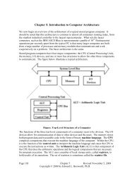
The Central Processing Unit (CPU)<br />
• The CPU has four main <strong>com</strong>ponents:<br />
1. The <strong>Control</strong> Unit (along with the IR) interprets the<br />
machine language instruction and issues the control<br />
signals to make the CPU execute that instruction.<br />
2. The ALU (Arithmetic Logic Unit) that does the<br />
arithmetic and logic.<br />
3. The Register Set (Register File) that stores temporary<br />
results related to the <strong>com</strong>putations. There are also<br />
Special Purpose Registers used by the <strong>Control</strong> Unit.<br />
4. An internal bus structure for <strong>com</strong>munication.
The <strong>Control</strong> Unit (Part 2)<br />
• The function of the control unit is to decode the<br />
binary machine word in the IR (Instruction Register)<br />
and issue appropriate control signals. These cause<br />
the <strong>com</strong>puter to execute its program.
Two Options for the <strong>Control</strong> Unit<br />
• <strong>Hardwired</strong>: The control signals are generated as<br />
an output of a set of basic logic gates, the input<br />
of which derives from the binary bits in the<br />
Instruction Register.<br />
• <strong>Microprogrammed</strong>: The control signals are<br />
generated by a microprogram that is stored in<br />
<strong>Control</strong> Read Only Memory.<br />
• The microcontroller fetches a control word from<br />
the CROM and places it into the MBR, from<br />
which control signals are emitted.
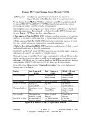
The <strong>Microprogrammed</strong> <strong>Control</strong> Unit
Design of the CU<br />
• The only function of the micro-control unit<br />
(CU) is to <strong>com</strong>pute the address of the CROM<br />
word next to be placed into the MBR.<br />
• As such, it is extremely primitive and simple.<br />
• Even for a large sophisticated <strong>com</strong>puter,<br />
design of the CU might be suitable as a<br />
project for undergraduate students.<br />
• This simplicity makes the unit very attractive.
The Boz-5: A Very Simple Computer<br />
• We shall use some material from a didactic<br />
<strong>com</strong>puter designed by your instructor to<br />
illustrate various control unit designs.<br />
• In this design, instruction execution is divided<br />
into three phases. We focus on the first of<br />
these phases: fetch, which fetches the next<br />
instruction and updates the PC.
The Common Fetch Sequence<br />
• In the Boz-5 design, the Fetch sequence is<br />
divided into four phases, each having duration<br />
of one clock pulse.<br />
• Here are the microoperations associated with<br />
the first three phases of the fetch sequence.<br />
• Step 1: (PC) MAR, READ.<br />
• Step 2: (PC) + 4 PC.<br />
• Step 3: (MBR) IR.
<strong>Control</strong> Signals are More Primitive<br />
• <strong>Control</strong> signals directly enable transfers, so<br />
they must be very low level.<br />
• Note that the inputs (Fetch, T0, T1, T2) are<br />
discrete binary signals.<br />
Fetch, T0: (PC) B1, tra1, B3 MAR, READ.<br />
Fetch, T1: (PC) B1, 4 B2, add, B3 PC.<br />
Fetch, T2: (MBR) B2, tra2, B3 IR.
The Boz-5 <strong>Control</strong> Signals<br />
• PC B1 Copy the contents of the PC onto bus B1<br />
• +4 B2 Copy the constant +4 onto B2.<br />
• MBR B2 Copy the contents of the MBR onto B2<br />
• tra1 Causes the ALU to copy the contents of B1 onto B3<br />
• tra2 Causes the ALU to copy the contents of B2 onto B3<br />
• add Causes the ALU to add the contents of B1 and B2,<br />
placing the sum onto B3.<br />
• read Causes the memory to be read; place the results in MBR<br />
• Bus3 MAR Copy the contents of B3 to the MAR<br />
• Bus3 PC Copy the contents of B3 to the PC<br />
• Bus3 IR Copy the contents of B3 to the IR
<strong>Hardwired</strong> Signal Generation<br />
• The first phase of the<br />
fetch sequence has<br />
Fetch = 1 and T0 = 1.<br />
• If Fetch = 1 and T0 = 1<br />
then<br />
tra1 = 1 (it is asserted)<br />
B3 MAR = 1<br />
read = 1<br />
PC B1 = 1
<strong>Microprogrammed</strong> Signals<br />
PC <br />
Bus1<br />
+1 <br />
Bus2<br />
MBR<br />
<br />
Bus2<br />
Bus3<br />
<br />
MAR<br />
Bus3<br />
PC<br />
Bus3<br />
IR<br />
• The microprogram can be written as<br />
10 0100 0101 0x245<br />
11 0010 1000 0x328<br />
00 1001 0010 0x092<br />
add tra1 tra2 read<br />
T0 1 0 0 1 0 0 0 1 0 1<br />
T1 1 1 0 0 1 0 1 0 0 0<br />
T2 0 0 1 0 0 1 0 0 1 0
Microprogramming Example<br />
• Consider the micro–memory associated with bus B1.<br />
• At address 105 we have MAR B1.<br />
• At address 106 we have R B1.
Horizontal and Vertical Microcode<br />
• Consider a bus, B1, that can be fed by seven<br />
different signal sources.<br />
• In horizontal microcode, each signal has a bit<br />
in the micro-memory. The B1 field would<br />
have 8 bits.<br />
• In vertical microcode, the field would have a<br />
binary encoding to indicate the single source<br />
to be placed on the bus; here 3 bits.
Advantages of Vertical Microcode<br />
• One advantage is that it allows a “narrower<br />
micro–memory”, fewer bits per word in the<br />
micro–memory. But memory is cheap.<br />
• The major advantage is that it prevents the<br />
assertion of two or more data sources on a<br />
given bus or two or more simultaneous ALU<br />
operations.
B1 With Vertical Microcode
Typical Microinstruction Format<br />
• Each microinstruction includes the address of<br />
the instruction to be executed next.<br />
• Here is a format that supports a branch. There<br />
are two 8-bit addresses. The signal S2 will<br />
indicate whether or not the branch is taken.<br />
• Non-branching instructions have the same<br />
value in both fields.<br />
Micro–Op B1 B2 B3 ALU M1 M2 S2 = 0 S2 = 1<br />
4 bits 4 bits 4 bits 4 bits 4 bits 4 bits 4 bits 8 bits 8 bits
Why Store Addresses in the Microcode<br />
• Here are two options for a sequence of control<br />
signals, taken out of context. The first uses a<br />
conditional branch.<br />
• 0x02C IR B1, R B2, add, B3 MAR<br />
0x02D If D = 0 Go To 0x030<br />
0x02E READ<br />
• Similar code in the modern style<br />
0x02C IR B1, R B2, add, B3 MAR, 0x030, 0x02E
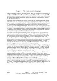
Maurice Wilkes<br />
• Maurice Wilkes worked in the Computing Laboratory at<br />
Cambridge University beginning in 1936, but mostly from<br />
1945 as he served in WW 2.<br />
• On May 6, 1949 the EDSAC was first operational, <strong>com</strong>puting<br />
the values of N 2 for 1 N 99. In 1951, Wilkes published<br />
The Preparation of Programs for Electronic Digital<br />
Computers, the first book on programming.<br />
• Also in 1951, Wilkes published a paper “The Best Way to<br />
Design an Automatic Calculating Machine” that described a<br />
technique that he called microprogramming. This<br />
technique is still in use today and still has the same name.
Wilkes’ Motivation<br />
• Here is a direct quote from Maurice Wilkes.<br />
• “As soon as we started programming, we<br />
found to our surprise that it wasn’t as easy to<br />
get programs right as we had thought. … I can<br />
remember the exact instant when I realized<br />
that a large part of my life from then on was<br />
going to be spent in finding mistakes in my<br />
own programs.”
The Complexity of the <strong>Control</strong> Unit<br />
• After his visit to the United States, Wilkes started<br />
to worry about the <strong>com</strong>plexity of the control unit<br />
of the EDVAC, then in design. Here is what he<br />
wrote later.<br />
• “It was not, I think, until I got back to Cambridge<br />
that I realized that the solution was to turn the<br />
control unit into a <strong>com</strong>puter in miniature by<br />
adding a second matrix to determine the flow of<br />
control at the micro-level and by providing for<br />
conditional microinstructions”.
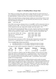
A Diode Matrix<br />
• A diode memory is just a collection of diodes<br />
connected in a matrix.
Problems in the 1950’s<br />
• In 1958, the EDSAC 2 became operational; it was<br />
the first microprogrammed <strong>com</strong>puter. The control<br />
unit used ROM made from magnetic cores.<br />
• There were two reasons that Wilkes’ idea did not<br />
take off in the 1950’s.<br />
1. The simple instruction sets of the time did not<br />
demand microprogramming, and<br />
2. The methods for fabricating a microprogram<br />
control store were not adequate.
Microprogramming is Taken Seriously<br />
• IBM introduced the System/360 in 1964. This<br />
caused microprogramming to be taken seriously<br />
as an option for designing control units. There<br />
were three reasons.<br />
1. The recent availability of memory units with<br />
sufficient reliability and reasonable cost.<br />
2. The fact that IBM took the technology seriously.<br />
3. The fact that IBM aggressively pushed the<br />
memory technology inside the <strong>com</strong>pany to<br />
make microprogramming feasible.
IBM’s Goals for Microprogramming<br />
• “Microprogramming in the System/360 …<br />
has been used to help design a fixed<br />
instruction set capable of reaching across a<br />
<strong>com</strong>patible line of machines in a wide range of<br />
performances. … [It] has, however, made it<br />
feasible for the smaller models of System/360<br />
to provide the same <strong>com</strong>prehensive<br />
instruction set as the large models.”
IBM’s Marketing Problem<br />
• The System/360 was a bold move to replace a<br />
number of in<strong>com</strong>patible designs:<br />
the IBM 1401, the IBM 7040, and IBM 7094.<br />
• Each of the older designs had a large customer<br />
base with considerable developed code.<br />
• None of the old code would run on the 360.<br />
• Honeywell, along with other <strong>com</strong>panies, began<br />
marketing newer <strong>com</strong>puters that would run the<br />
old code.<br />
• Customers might abandon IBM.
Emulation on the S/360<br />
• IBM was “spared mass defection of former customers”<br />
when engineers working on the Model 30 suggested the<br />
use of an extra control store on the micro–programmed<br />
control unit to allow the Model 30 to execute IBM 1401<br />
instructions in native mode.<br />
• The effort lead to the ability to execute native mode<br />
software for both the IBM 1401 and IBM 700 series.<br />
Moss termed their work as “emulation”.<br />
• The emulators they designed worked well enough so that<br />
many customers never converted legacy software and<br />
instead ran it for many years on System/360<br />
hardware using emulation. This was a great marketing<br />
success for IBM.
The 1960’s and 1970’s<br />
• In the 1960s and 1970s, microprogramming was one of the<br />
most important techniques used in implementing<br />
machines. Through most of that period, machines were<br />
implemented with discrete <strong>com</strong>ponents or MSI (mediumscale<br />
integration—fewer than 1000 gates per chip)<br />
• The hardwired implementations were faster, but too costly<br />
for most machines. Furthermore, it was very difficult to get<br />
the control correct, and changing ROMs was easier than<br />
replacing a random logic control unit.<br />
• Eventually, microprogrammed control was implemented in<br />
RAM, to allow changes late in the design cycle, and even in<br />
the field after a machine shipped.
Benefits of Microprogramming<br />
• As noted above, the primary impediment to adoption<br />
of microprogramming was that sufficiently fast control<br />
memory was not readily available.<br />
• When the necessary memory became available,<br />
microprogramming became popular.<br />
• The main advantage of microprogramming was that it<br />
handled difficulties associated with virtual memory,<br />
especially restarting instructions after page faults.<br />
• The IBM System 370 Model 138 implemented virtual<br />
memory entirely in microcode.
The IBM XT/370<br />
• IBM was attempting to regain dominance in the<br />
desktop market. They noted that both the S/370 and<br />
the Motorola 68000 used sixteen 32–bit general<br />
purpose registers.<br />
• In 1984 IBM announced the XT/370, a “370 on a<br />
desktop”. The design used a pair of Motorola 68000s<br />
re–microprogrammed to emulate the S/370 instruction<br />
set. Two units were required because the control store<br />
on the Motorola was too small for the S/370.<br />
• As a <strong>com</strong>puter the project was successful. It failed<br />
because IBM wanted full S/370 prices for the software<br />
to run on the XT/370.
Side–Effects of Microprogramming<br />
• It is a simple fact that the introduction of<br />
microprogramming allowed the development of<br />
Instruction Set Architectures of almost arbitrary<br />
<strong>com</strong>plexity.<br />
• The VAX series, marketed by the Digital<br />
Equipment Corporation, is usually seen as the<br />
“high water mark” of microprogrammed designs.<br />
The later VAX designs supported an Instruction<br />
Set Architecture with more than 300 instructions<br />
and more than a dozen addressing modes.
Microprogramming and<br />
Memory Technologies<br />
• The drawback of microcode has always been<br />
memory performance; the CPU clock cycle is<br />
limited by the time to read the memory.<br />
• In the 1950’s, microprogramming was<br />
impractical for two reasons.<br />
1. The memory available was not reliable, and<br />
2. The memory available was the same slow<br />
core memory as used in the main memory of<br />
the <strong>com</strong>puter.
Microprogramming and<br />
Memory Technologies<br />
• In the late 1960’s, semiconductor memory<br />
(SRAM) became available for the control store. It<br />
was ten times faster than the DRAM used in main<br />
memory. This speed difference that opened the<br />
way for microcode.<br />
• In the late 1970’s, cache memories using the<br />
SRAM became popular. At this point, the CROM<br />
lost its speed advantage.<br />
• For these reasons, instruction sets invented since<br />
1985 have not relied on microcode.
Microprogramming:<br />
The Late Evolution<br />
• Events that lead to the reduced emphasis on<br />
microprogramming include:<br />
1. The availability of VLSI technology, which allowed a<br />
number of improvements, including on–chip cache<br />
memory, at reasonable cost.<br />
2. The availability of ASIC (Application Specific Integrated<br />
Circuits) and FPGA (Field Programmable Gate Arrays),<br />
each of which could be used to create custom circuits that<br />
were easily tested and reconfigured.<br />
3. The beginning of the RISC (Reduced Instruction Set<br />
Computer) movement, with its realization that <strong>com</strong>plex<br />
instruction sets were not required.
What Happened to Microcode<br />
• <strong>Control</strong> units for RISC designs tend not to use<br />
microprogramming, but the simpler and faster<br />
hardwired designs.<br />
• One reason is that the simplicity of the control<br />
unit does not require microprogramming.<br />
• Another possible reason is that the speed of a<br />
modern pipelined control unit requires control<br />
signals to be issued at a rate faster than SRAM<br />
read-only memory can deliver them.