Technical Data - Hytek
Technical Data - Hytek
Technical Data - Hytek

You also want an ePaper? Increase the reach of your titles
YUMPU automatically turns print PDFs into web optimized ePapers that Google loves.
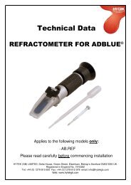
<strong>Technical</strong> <strong>Data</strong><br />
HYTEK PULS.800 FLOWMETER<br />
PULSE TRANSMITTER<br />
Applies to the following models only:<br />
- PULS.800<br />
Please read carefully before commencing installation<br />
Registered Office: HYTEK (GB) LIMITED, Delta House, Green Street, Elsenham, Bishop’s Stortford CM22 6DS UK.<br />
Registered in England No. 1915382<br />
Tel: +44 (0) 1279 815 600 Fax: +44 (0) 1279 812 978 email: info@hytekgb.com<br />
Web: www.hytekgb.com
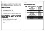
ENVIRONMENTAL INFORMATION<br />
European Directives 2002/96/EC and 2003/108/EC require<br />
that the equipment bearing this symbol on the product an/or<br />
its packaging must not be disposed of with unsorted<br />
municipal waste. The symbol indicates that this product<br />
must be disposed of separately from regular household<br />
waste streams. It is your responsibility to dispose of this and<br />
other electric and electronic equipment via designated<br />
collection facilities appointed by the government or local<br />
authorities.<br />
IMPORTANT WARNING NOTES<br />
1. The pulse transmitter MUST NOT be used to measure petrol<br />
or other flammable liquids.<br />
2. It is designed for use with diesel, gas oil, hydraulic oil and<br />
heating oil.<br />
3. It must not be sited adjacent to a petrol dispenser or in any<br />
other hazardous zone.<br />
4. Installation of this equipment should be carried out by a<br />
qualified fuel installation engineer.<br />
5. The installation must conform to all relevant electrical and<br />
local authority regulations and standards.<br />
PRODUCT DESCRIPTION<br />
The Pulse Transmitter utilizes advanced CMOS technology to<br />
achieve a multi-channel solution to the problems of parasitic<br />
pulsing associated with single channel pulse transmitters. The<br />
device requires minimal supply current, accepts a wide supply<br />
voltage range and has a large output current sink capacity as well<br />
as an option for volt-free output contacts via a plug in reed relay.<br />
The Pulse Transmitter has been designed to maximize the amount<br />
of disc rotation available without false generation of pulses<br />
resulting in a vast improvement over conventional single channel<br />
solutions.<br />
PULSE OUTPUT<br />
PULS.800: 10 pulses per litre<br />
S625/3<br />
2
INSTALLATION<br />
1. Remove meter front cover, dial face, register.<br />
2. Remove the bevelled pinion gear<br />
3. Place the nylon washer over the protruding gear shaft before fitting the<br />
modified bevel gear with the slotted disc fitted.<br />
4. Remove the bottom two meter bolts. See photo 1 on page 4.<br />
5. Ensure that the meter inlet/outlet ports are in the desired orientation. If<br />
not then turn the meter backplate to the desired position before<br />
proceeding.<br />
6. Fit the pulser using the M6 bolts, washers and nuts supplied. Ensure<br />
that the bracket is pushed fully downwards before tightening bolts. See<br />
photo 2 on page 4.<br />
7. Ensure the slotted disc is centrally located between the pulser emitter<br />
and receiver and does not rub on either. See photo 2 on page 4.<br />
8. Refit the register.<br />
9. Drill a 12mm hole in the meter cover in the location shown on the<br />
pulser location diagram and photo on page 5. Fit the TA.GLND as<br />
shown.<br />
10. Slide signal flex through gland leaving 140mm of flex inside the meter<br />
casing. Tighten gland and carefully refit meter front cover and dial face<br />
insuring signal flex is coiled up inside casing without being snagged or<br />
pinched.<br />
11. Connect pulser wires as per connection diagram on page 6.<br />
12. Ensure that the pulser functions correctly and check that when the<br />
meter is reset it doesn’t clock up extra pulses.<br />
S625/3<br />
3
PHOTOS<br />
PHOTO 1<br />
REMOVE METER BOLTS<br />
PHOTO 2<br />
Ensure bracket is<br />
pushed fully<br />
downwards<br />
before tightening<br />
bolts.<br />
S625/3<br />
4
PULSER LOCATION DIAGRAM<br />
PHOTO 3<br />
GLAND LOCATION<br />
S625/3<br />
5
CONNECTION DIAGRAM<br />
Black<br />
Green<br />
0V<br />
To Key System Pulse Input<br />
n<br />
Yellow<br />
Blue<br />
Screen<br />
To Key System Output OR 0V<br />
DO NOT USE<br />
Frame Ground<br />
Red<br />
V+<br />
Connect the pulse transmitter as shown in the connection diagram.<br />
The connections are rated as follows:<br />
Supply Ratings:<br />
Voltage - 5 -12V DC<br />
Current - 5 -40 mA<br />
Passive Contact Ratings:<br />
Voltage - 24V DC Max.<br />
Current - 1A Max.<br />
Power - 15W Max.<br />
NB: The pulse transmitter pulse input and output (green and<br />
yellow) wires are connected across the passive contacts of the<br />
transmitter relay. If the key system, to which the transmitter is to<br />
be connected, has only 3 wires (0 volts, +volts and “signal”) the<br />
transmitter 0V (black) and the yellow pulse wire can be linked<br />
together. The key system +volts can then be connected to +V<br />
(red), 0 volts to 0V (black) and “signal” to the green pulse wire.<br />
This will “drag” the signal down to 0 volts every pulse.<br />
S625/3<br />
6
NOTES<br />
S625/3<br />
7
E.C. DECLARATION OF CONFORMITY<br />
Date of Issue: 10 th September2009<br />
Amended: 23 rd December 2009<br />
Equipment Details:<br />
<strong>Hytek</strong> Flowmeter Pulse<br />
Transmitters<br />
PULS.800, PULS.900, PULS.FM4<br />
PULS.K33, PULS.K44<br />
Applicable Standards:<br />
Machinery Directive 2006/42/EC<br />
Waste Electrical and Electronic<br />
Equipment<br />
Regulations 2006<br />
2002/96/EC<br />
2003/108/EC<br />
Authorized By:<br />
Clive Wellings<br />
<strong>Technical</strong> Manager <strong>Hytek</strong><br />
Declaration Number:<br />
EC072<br />
S625/3<br />
8