Technical Data SPT120A DIRECT DRIVE PUMP UNIT 230v ... - Hytek
Technical Data SPT120A DIRECT DRIVE PUMP UNIT 230v ... - Hytek
Technical Data SPT120A DIRECT DRIVE PUMP UNIT 230v ... - Hytek

Create successful ePaper yourself
Turn your PDF publications into a flip-book with our unique Google optimized e-Paper software.
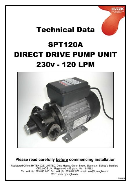
<strong>Technical</strong> <strong>Data</strong><br />
<strong>SPT120A</strong><br />
<strong>DIRECT</strong> <strong>DRIVE</strong> <strong>PUMP</strong> <strong>UNIT</strong><br />
<strong>230v</strong> - 120 LPM<br />
Please read carefully before commencing installation<br />
Registered Office: HYTEK (GB) LIMITED, Delta House, Green Street, Elsenham, Bishop’s Stortford<br />
CM22 6DS UK. Registered in England No. 1915382<br />
Tel: +44 (0) 1279 815 600 Fax: +44 (0) 1279 812 978 email: info@hytekgb.com<br />
Web: www.hytekgb.com<br />
S561/4
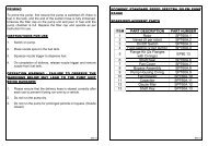
ENVIRONMENTAL INFORMATION<br />
European Directives 2002/96/EC and 2003/108/EC require that the<br />
equipment bearing this symbol on the product an/or its packaging must<br />
not be disposed of with unsorted municipal waste. The symbol<br />
indicates that this product must be disposed of separately from regular<br />
household waste streams. It is your responsibility to dispose of this and<br />
other electric and electronic equipment via designated collection<br />
facilities appointed by the government or local authorities.<br />
IMPORTANT WARNING NOTES<br />
1. This dispenser MUST NOT be used to dispense petrol or other<br />
flammable liquids.<br />
2. It must not be sited adjacent to a petrol dispenser or any other<br />
hazardous zone.<br />
3. On above ground storage tanks, a spring loaded angle check valve or<br />
pressure regulating valve must be fitted at the tank outlet to prevent<br />
loss of fuel under gravity in the event of vandalism or accidental<br />
damage.<br />
4. Installation of this equipment and its associated tank, pipe work and<br />
fittings should only be carried out by qualified fuel installation<br />
engineers.<br />
5. The installation must conform to all relevant electrical and local<br />
authority regulations and standards.<br />
6. The supplied strainer or a suitable strainer/filter MUST be fitted to the<br />
suction line to prevent the pump unit from being damaged.<br />
S561/4
INSTALLATION<br />
1. If no wall-mounting bracket is supplied, mount on a horizontal surface<br />
using the holes provided in the pump feet, or use a tank/barrel mount<br />
adaptor if provided.<br />
2. Fit the supplied strainer to the pump inlet.<br />
3. Connect the pipe from the tank to the suction inlet of the pump. The<br />
inlet thread is 1 ½” BSP female. If the pump is more than 2m from the<br />
tank the pipe should be 1½ diameter reducing to the appropriate size<br />
just before the pump inlet. Seal the threads with a suitable threadsealing<br />
compound.<br />
4. Connect a suitable “soft wall” hose to the pump outlet. In turn, fit a<br />
suitable trigger or automatic nozzle onto the hose. Seal both with a<br />
suitable thread-sealing compound.<br />
5. Connect the flying lead to a suitable power supply, fused at 10 amps<br />
for <strong>230v</strong> AC and 16A for the 110v AC as follows:<br />
<strong>230v</strong> AC:<br />
Brown – Live<br />
Blue – Neutral<br />
Yellow/Green – Earth<br />
6. To prime the pump, first ensure the pump is switched off, there is fuel<br />
in the tank, and the end of the suction hose is fully immersed. Unscrew<br />
the filter cap and pour in fuel until the pump chamber is full. Replace<br />
the filter cap and operate as per instruction for use.<br />
S561/4
INSTRUCTIONS FOR USE<br />
1. Switch on pump.<br />
2. Place nozzle spout in the fuel tank.<br />
3. Squeeze nozzle trigger to dispense fuel.<br />
4. On completion of delivery, release nozzle trigger and remove nozzle<br />
from fuel tank.<br />
OPERATION WARNING - FAILURE TO OBSERVE THE<br />
WARNINGS BELOW MAY LEAD TO THE <strong>PUMP</strong> <strong>UNIT</strong> BEING<br />
DAMAGED:<br />
1. Please ensure that the delivery hose is stowed correctly after each use<br />
to prevent it being run over by a vehicle.<br />
2. Do not run the pump dry.<br />
3. Do not run the pump for prolonged periods on bypass. (Nozzle closed)<br />
4. The supplied strainer or a suitable strainer/filter MUST be fitted to the<br />
suction line to prevent the pump unit from being damaged.<br />
S561/4
DIMENSIONS<br />
S561/4
PARTS DIAGRAM<br />
PARTS LIST<br />
DIAGRAM No. PART NUMBER DESCRIPTION<br />
9 <strong>SPT120A</strong>.1 ROTOR<br />
10 <strong>SPT120A</strong>.2 VANE<br />
14 <strong>SPT120A</strong>.3 SHAFT KEY<br />
16 <strong>SPT120A</strong>.4 ON/OFF SWITCH<br />
7 <strong>SPT120A</strong>.5 <strong>PUMP</strong> HOUSING<br />
8 <strong>SPT120A</strong>.6 <strong>PUMP</strong> HOUSING O-RING<br />
20 <strong>SPT120A</strong>.7 SHAFT SEAL<br />
S561/4
NOTES<br />
S561/4
E.C. DECLARATION OF CONFORMITY<br />
Date of Issue: 23/12/09<br />
Equipment Details:<br />
Applicable standards:<br />
<strong>SPT120A</strong> Pump Unit And Motor<br />
EMC<br />
EN61000-6-3:2007<br />
EN61000-3-2:2006<br />
EN61000-3-3:2008 Emissions<br />
EN61000-6-1:2007 Immunity<br />
2006/95/EC Electrical Equipment (Low Voltage)<br />
Machinery Directive 2006/42/EC<br />
The Pressure Equipment Regulations<br />
1999 S.I. 1999/2001<br />
Entry Into Force:- 29 November 1999<br />
Amended to S.I. 2002/1267<br />
Pressure Equipment Directive 97/23/EC<br />
Waste Electrical and Electronic Equipment<br />
Regulations 2006<br />
2002/96/EC 2003/108/EC<br />
Authorized By:<br />
Declaration Number:<br />
Clive Wellings<br />
<strong>Technical</strong> Manager <strong>Hytek</strong><br />
EC019/5<br />
S561/4