HYTEK TANK ALARM
HYTEK TANK ALARM
HYTEK TANK ALARM

Create successful ePaper yourself
Turn your PDF publications into a flip-book with our unique Google optimized e-Paper software.
Technical Data<br />
<strong>HYTEK</strong> <strong>TANK</strong> <strong>ALARM</strong><br />
Please read carefully before commencing installation<br />
Registered Office: <strong>HYTEK</strong> (GB) LIMITED, Delta House, Green Street, Elsenham, Bishop’s Stortford<br />
CM22 6DS UK. Registered in England No. 1915382<br />
Tel: +44 (0) 1279 815 600 Fax: +44 (0) 1279 812 978 email: info@hytekgb.com<br />
Web: www.hytekgb.com<br />
S652/1
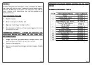
ENVIRONMENTAL INFORMATION<br />
European Directives 2002/96/EC and 2003/108/EC require that the<br />
equipment bearing this symbol on the product an/or its packaging must<br />
not be disposed of with unsorted municipal waste. The symbol<br />
indicates that this product must be disposed of separately from regular<br />
household waste streams. It is your responsibility to dispose of this and<br />
other electric and electronic equipment via designated collection<br />
facilities appointed by the government or local authorities.<br />
IMPORTANT WARNING NOTES<br />
1. The Hytek Tank Alarm MUST NOT be used to monitor petrol or other<br />
highly flammable liquids.<br />
2. It is designed for use with diesel, gas oil, water, hydraulic oil and<br />
heating oil.<br />
3. It must not be sited adjacent to a petrol dispenser or in any other<br />
hazardous zone.<br />
4. It must not be sited below ground level.<br />
5. Installation of this equipment should be carried out by a qualified fuel<br />
installation engineer.<br />
6. The installation must conform to all relevant electrical and local<br />
authority regulations and standards.<br />
7. Only Hytek float switches can be used with the Hytek alarm.<br />
PRODUCT DESCRIPTION<br />
The Hytek Tank Alarm is designed to provide visual and audible alarms<br />
whenever a predetermined level in a storage tank is reached.<br />
The system consists of a maximum of three-weighted float switches and<br />
an IP55 rated weatherproof enclosure containing the visual and audible<br />
alarms and the electronic PCB.<br />
S652/1
SPECIFICATION<br />
MAINS VERSION<br />
- 110/230V 3 channel alarm.<br />
- IP55 weatherproof enclosure, for outside mounting.<br />
- Each channel can be used as an overfill, low level or bund alarm.<br />
- High power alarm sounder, 98db at 1m.<br />
- High visibility flashing zenon beacon.<br />
- Test button checks float switches as well as beacon & sounder.<br />
BATTERY VERSION<br />
- Battery 3 channel alarm.<br />
- Each channel can be used as an overfill, low level or bund alarm.<br />
- High power alarm sounder, 98db at 1m.<br />
- No zenon beacon, but individual channel LED’s.<br />
- Test button checks float switches as well as batteries & sounder.<br />
- Battery life depends on number of test & alarm incidents.<br />
INSTALLATION INSTRUCTIONS<br />
MOUNTING<br />
The float switch assembly is supplied with 5 metres of 2-core PUR fuel<br />
resistant cable that may be extended, as necessary, up to 100 metres.<br />
1. Remove front display lid from alarm box and disconnect ribbon cable.<br />
Place the lid somewhere clean and safe.<br />
2. Using wall-mounting bracket, fix alarm box into position.<br />
3. Self-adhesive product labels are supplied and are to be fixed alongside<br />
the corresponding channel LED indicator on the front of the alarm unit.<br />
POWER SUPPLY<br />
4. The TA2.POW is designed to have a continual 230Vac supply fused at a<br />
rating of 6 amps max. The TA2.POW.110 is designed to have continual<br />
110V AC supply fused at a rating of 6 amps max. The TA2.BAT has an<br />
internal battery power supply. The TA2.12 is designed to have a<br />
continuous 12V power supply. See Connections diagram.<br />
S652/1
CONNECTIONS DIAGRAM<br />
FLOAT SWITCH INSTALLATION<br />
5. To ensure the float switch is positioned at the correct depth in the tank,<br />
locate the gland, fitted to the gland plate, at the appropriate point along<br />
the float switch cable.<br />
Carefully install float switch through a 30mm hole in the top of the tank,<br />
ensuring the sealing gasket is in place. Secure the gland plate to the<br />
tank using two self-tapping screws (not supplied). See Float switch<br />
installation diagram (page 3) Alternatively, for steel tank installations, an<br />
optional 11/2” brass cap (Hytek order ref - TA.CAP) can be used.<br />
NB: Installation of the float switch should be as far away from the fill<br />
point of the tank as possible.<br />
S652/1
FLOAT SWITCH INSTALLATION DIAGRAM<br />
FLOAT SWITCH ACTIVATION AND CONFIGURATION<br />
6. Connect the float switch cables to the float switch terminals inside the<br />
alarm box as per connections diagram.<br />
7. After connecting the desired amount of float switches, activate the<br />
corresponding channels by setting the appropriate channel activation<br />
dipswitch to "ON" position. See Dip switch settings diagram.<br />
NB: If a channel activation dipswitch is in the "OFF" position and a<br />
float switch connected to the corresponding terminals is operated,<br />
the alarm will not function.<br />
8. Set the high/low level dipswitches to the appropriate position to enable<br />
the corresponding float switches to detect either a high or low level<br />
situation. See Dip switch settings diagram.<br />
NB: After changing any dipswitch settings press the "RESET" button<br />
shown on Connections diagram.<br />
S652/1
DIPSWITCH SETTINGS DIAGRAM<br />
CHANNEL SWITCHES<br />
ON<br />
OFF<br />
FLOAT SWITCHES<br />
LOW<br />
HIGH<br />
EXTERNAL RELAY OUTPUTS<br />
9. Where external output relays have been fitted connect external cabling<br />
as per connections diagram. The relay contacts are rated at 250 volts,<br />
10 amps max.<br />
NB: The relays are a switch only and do not offer a power source for<br />
any external equipment. The relays MUST NOT be used to activate any<br />
equipment such as fuel pumps or safety valves.<br />
COMPLETION OF INSTALLATION<br />
10. Install batteries provided (TA2.BAT & TA2.BATR Only).<br />
11. Refit lid to alarm box ensuring that ribbon cable is reconnected to the<br />
main PCB and the lid seal is in place.<br />
12. Switch on power. The green "POWER" LED should illuminate<br />
(TA2.POW, TA2.POWR, TA2.POW.110 & TA2.POWR.110 only).<br />
S652/1
OPERATION<br />
<strong>ALARM</strong> CONDITION<br />
When a high or low level alarm condition occurs the corresponding channel<br />
LED, on the tank alarm lid is illuminated and the sounder/beacon will<br />
activate. The external relay will also be activated.<br />
<strong>ALARM</strong> MUTE<br />
Pressing the mute button will silence the sounder and stop the beacon<br />
flashing when an alarm condition is occurring. This will not de-activate any<br />
relays (if fitted). The relays will only be de-activated when float switch<br />
returns to its normal position.<br />
If the mute button is not depressed the sounder will silence after 20<br />
minutes leaving the beacon and channel LED on.<br />
The channel LED will remain on until the alarm condition has been rectified<br />
(float switch returns to its normal position).<br />
<strong>ALARM</strong> TEST<br />
To test the Tank Alarm, push the test button on the lid and hold for<br />
approximately 2 seconds. If the Tank Alarm is functioning correctly the<br />
sounder should activate for a short period.<br />
On the battery version of the Tank Alarm (TA2.BAT & TA2.BATR) the<br />
battery test light should flash three times and then the sounder should<br />
activate.<br />
If no sounder is heard and no channel LED’s on, check batteries and<br />
change as necessary.<br />
If the sounder does not activate the test has failed and a channel LED will<br />
flash to indicate which float switch channel is faulty.<br />
NB: Always push the Tank Alarm test button before filling the tank.<br />
S652/1
FITTING DIMENSIONS<br />
S652/1
PARTS LIST<br />
<strong>HYTEK</strong> <strong>TANK</strong> <strong>ALARM</strong> PARTS LIST<br />
PART EXPLODED PART<br />
NO. VIEW REF DESCRIPTION<br />
1▼ TA2.LID Tank alarm lid with all components - MAINS<br />
► TA2.LID.BAT Tank alarm lid with all components - BATTERY<br />
2 TA.BEACON Tank alarm amber beacon<br />
3▼ TA.LABM2 Display lid label (mains)<br />
► TA.LABB2 Display lid label (battery)*<br />
4 TA.SOUND Tank alarm sounder<br />
5 TC.AT Tank alarm test button<br />
6 TC.AS Tank alarm mute button<br />
7 TA.GLND Cable gland PG7<br />
8 TA.BOX2 Tank alarm box (base only)<br />
9▼ TA.PCBMAINSR Alarm PCB 230Vac with Relays<br />
► TA.PCBMAINS Alarm PCB 230Vac*<br />
► TA.PCB.110R Alarm PCB 110Vac with Relays*<br />
► TA.PCB.110 Alarm PCB 110Vac*<br />
► TA.PCBBATTR Alarm PCB 6Vdc Battery with Relays*<br />
► TA.PCBBATT Alarm PCB 6Vdc Battery*<br />
10 TA.RELAY 10 amp relay (3 per unit)<br />
11 TA.CONM Plug connector (230/110v mains)<br />
12 TA.CONR Plug connector (relays)<br />
13 TA.CONF Plug connector (floats)<br />
14 BLANK.12.7 12.7mm hole blank *<br />
15 TA.LABP Product label (9 labels per sheet) *<br />
16 TA.PCBDISP Alarm display PCB*<br />
*not shown<br />
SPARES<br />
PART NUMBER<br />
TA.F2<br />
TA.F2.10<br />
TA.FS<br />
TA.CAP<br />
TA.CABLE<br />
TA.CABEXT<br />
TA.BATTERY<br />
DESCRIPTION<br />
5m universal float switch<br />
10m universal float switch<br />
5m stainless steel float switch<br />
1 ½” threaded brass cap for steel tanks<br />
Extra cable to extend float switches<br />
Use to join extra cable - IP68 rated<br />
Type D battery (4 per unit)<br />
S652/1
OUTSIDE VIEW<br />
1<br />
2<br />
3<br />
5<br />
4<br />
6<br />
7<br />
TA2.POW (230V AC) - SHOWN<br />
S652/1
INSIDE VIEW<br />
9<br />
8<br />
11<br />
10<br />
12<br />
13<br />
TA2.POWR (230V AC) - SHOWN<br />
S652/1
E.C. DECLARATION OF CONFORMITY<br />
Date of Issue: 11 th March 2009<br />
Equipment Details: TA2.BAT, TA2.BATR, TA2.POW,<br />
TA2.POWR Tank Alarms<br />
Applicable Standards: EMC<br />
EN61326:1997 Class B Emissions<br />
(+A1/A2)<br />
EN61326:1997 Industrial Location<br />
Immunity (+A1/A2)<br />
EN61000-3-3:1995<br />
Electromagnetic Compatibility<br />
(+A1) Part 3:Limits – section 3<br />
2006/95/EC Electrical Equipment<br />
(Low Voltage)<br />
S.I. 1992/3037<br />
S.I. 1994/2063 (Amendment)<br />
Entry Into Force:- 1 January 1993<br />
Primary Legislation:- The European<br />
Communities Act 1972<br />
Machinery Directive 98/37/EC (2006/42/EC)<br />
Waste Electrical and Electronic Equipment<br />
Regulations 2006 2002/96/EC<br />
2003/108/EC<br />
Certificate Numbers EMC test report number R1975 Issue1<br />
and Details: By dB Technology<br />
23 Headington Drive<br />
Cherry Hinton<br />
Cambridge<br />
CB1 4HE<br />
Authorized By: Clive Wellings - Technical Manager<br />
Declaration Number: EC027<br />
S652/1